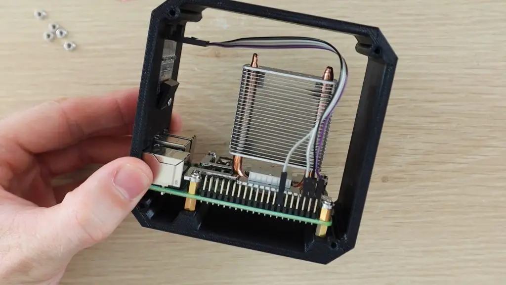
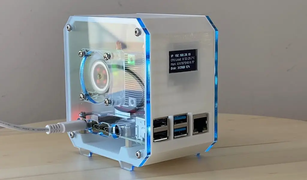
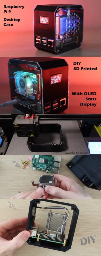
Today I’m going to be showing you how to make your own desktop case for a Raspberry Pi 4, which looks like a mini desktop pc.
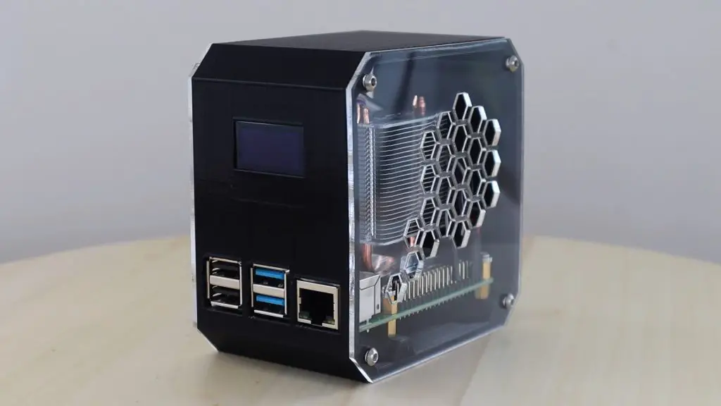
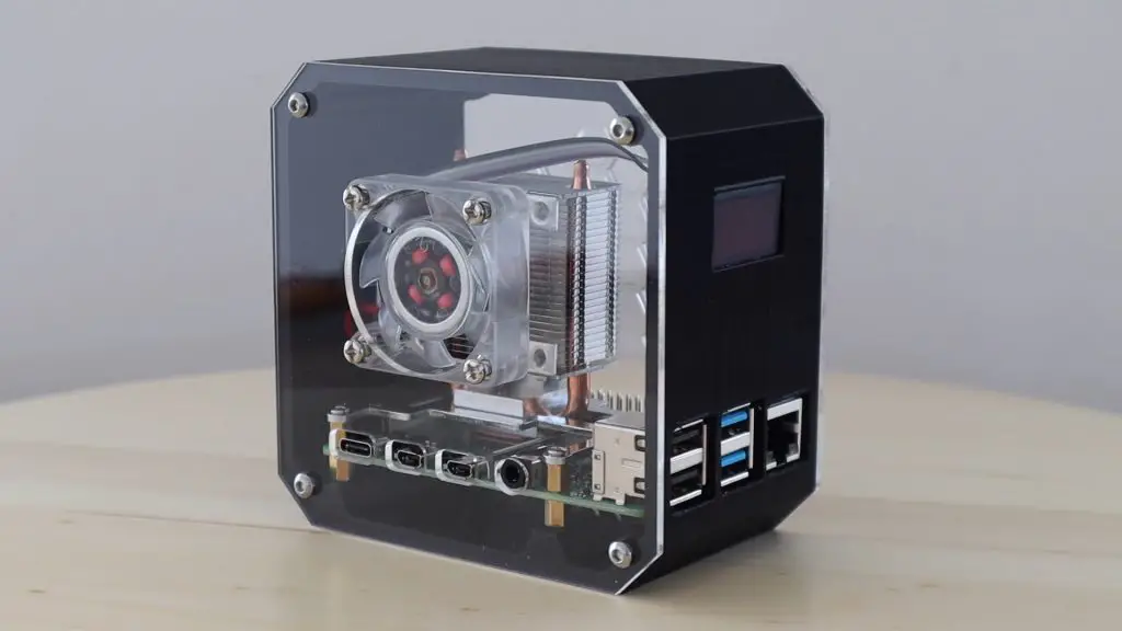
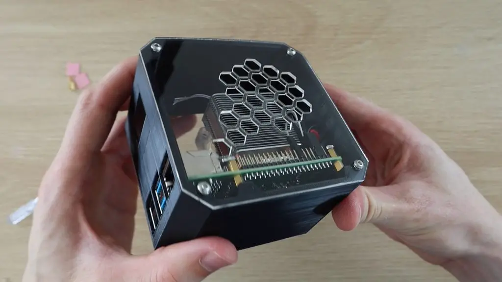
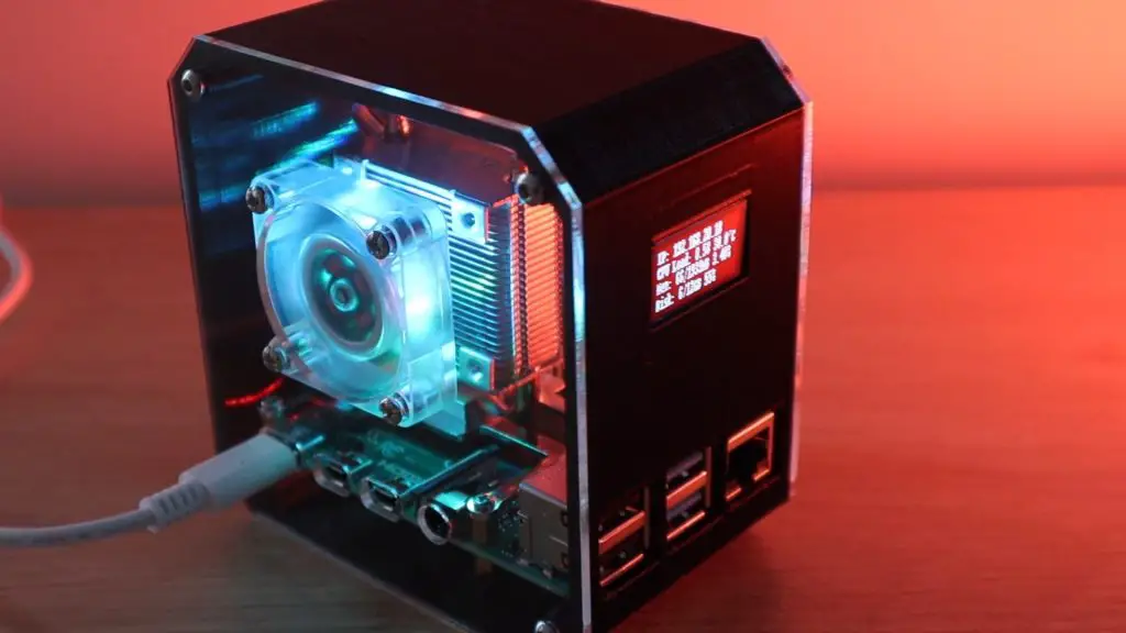
The body of the case is 3D printed and it has clear acrylic sides so that you’re able to see into it. I’ve used an Ice Tower to cool the CPU, but have mounted the fan onto the side of the case rather than on the heatsink.
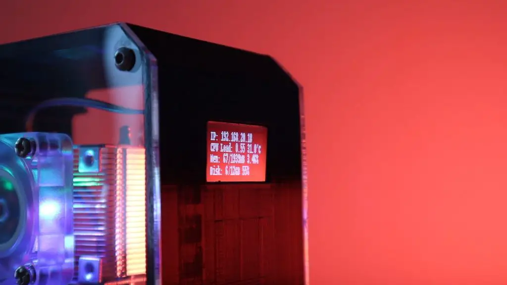
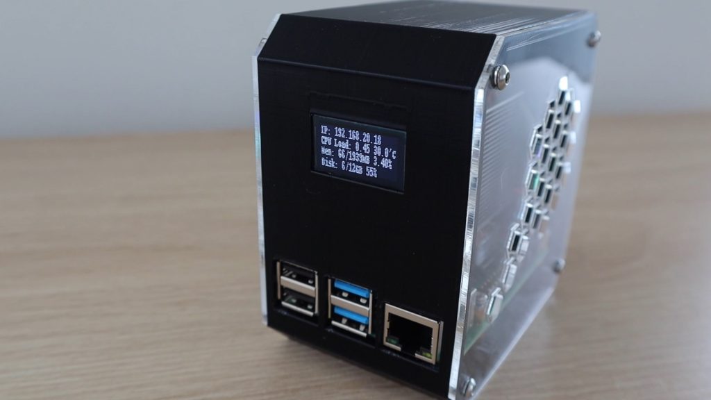
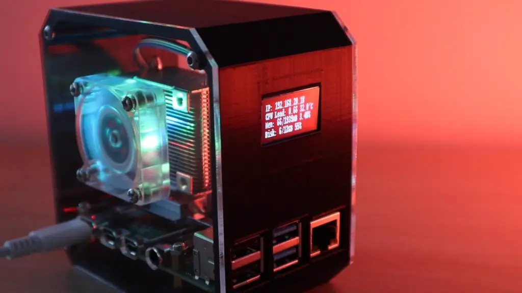
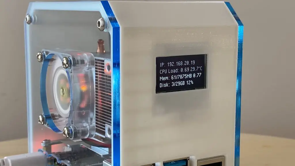
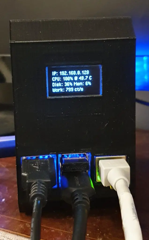
I’ve also included an OLED display on the front of the case which displays the Pi’s IP address and some stats like the CPU, storage and memory usage, and the CPU temperature.
You can now buy a pre-made kit for this Raspberry Pi 4 Desktop Case – Buy Here.
Here’s a video of the build and the case and display in operation:
What You Need To Make Your Own Raspberry Pi 4 Desktop Case
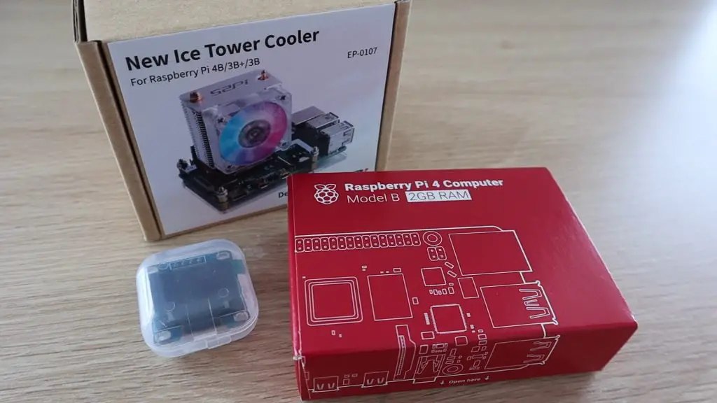
- Raspberry Pi 4 – Buy Here
- Any Raspberry Pi 4 model is fine
- Micro SD Card – Buy Here
- Raspberry Pi Power Supply – Buy Here
- Ice Tower – Buy Here
- I2C OLED Display – Buy Here
- Ribbon Cable – Buy Here
- Female Pin Headers – Buy Here
- Machine Screws – Buy Here
- 2mm Acrylic – Buy Here
- Black PLA Filament – Buy Here
In addition to the above, you’ll also need to have access to a 3D printer to print the plastic portion of the case.
I use the Creality Ender 3 Pro which I’ve found to produce great quality prints and is quite affordable.
3D Printer – Creality Ender 3 Pro – Buy Here
You don’t need a laser cutter for this build, although it does help significantly with making the sides. You can also use an online laser cutting service or simply cut your own sides using hand tools. I’ve used a Desktop K40 laser cutter/engraver.
Laser Cutter – K40 – Buy Here
Note: The above parts are affiliate links. By purchasing products through the above links, you’ll be supporting this channel, with no additional cost to you.
Making The Raspberry Pi 4 Desktop Case
3D Printing The Body
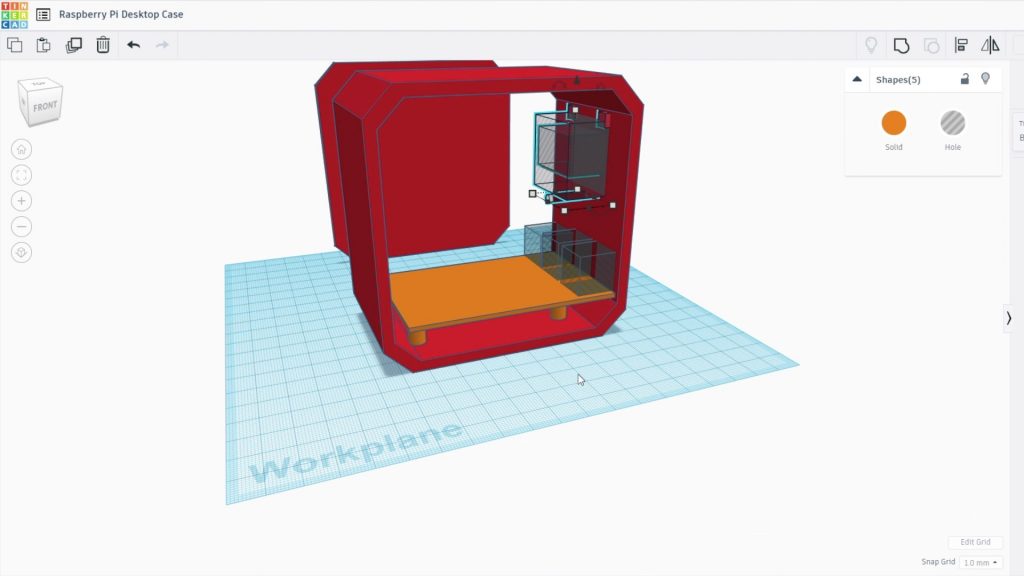
I started out by designing the 3D printed body of the case in Tinkercad.
Note: This design is copyrighted and is available for your personal, non-commercial use only. It may not be reproduced for commercial gain or republished in any form.
I’ve also put together a pack with some additional case variations which is available through this link – Additional 3D Print Files. This pack includes:
- Case With SD Card Cutout
- Case With OLED Display On The Other Side (USB & Ethernet Ports On Back)
- Case With No OLED Display Cutout
- Additional Side Panel Design With Larger HDMI Cutout
I drew a rough outline of the case and then positioned the Raspberry Pi within the case so that the USB and Ethernet ports are available through the front and the Power, HDMI, and audio ports are accessed through the side panel.
The OLED display is positioned on the front of the case above the ports. The OLED display will be held in place with two small clips on the top edge and a screw with a plastic clip at the bottom, a design which I’ve used before on my Arduino based reaction timer.
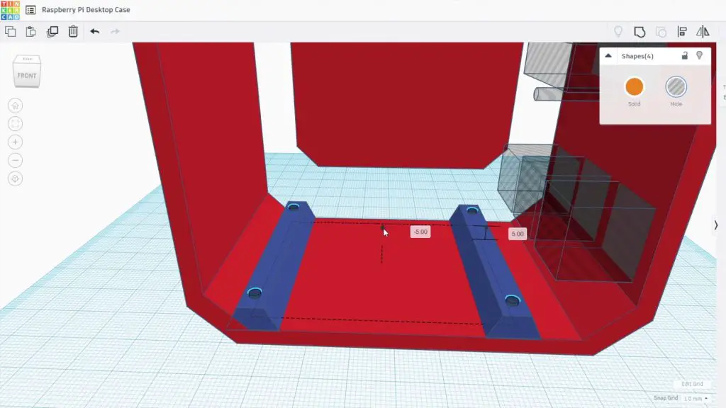
The Pi is going to be mounted onto the brass standoffs which came with the Ice Tower, so I added some holes to accommodate the M2.5 threads.
I don’t remove the SD card on the back of the Pi very often, so I didn’t add a cut-out for it. If you do, then just add a circular cut-out to the case at the back so that you can still access it. It is going to be a bit of a chore to swap the SD card if you don’t have this cut-out as you’ll need to remove the Pi from the case to access it, I’m happy with doing this if I ever need to change the card.
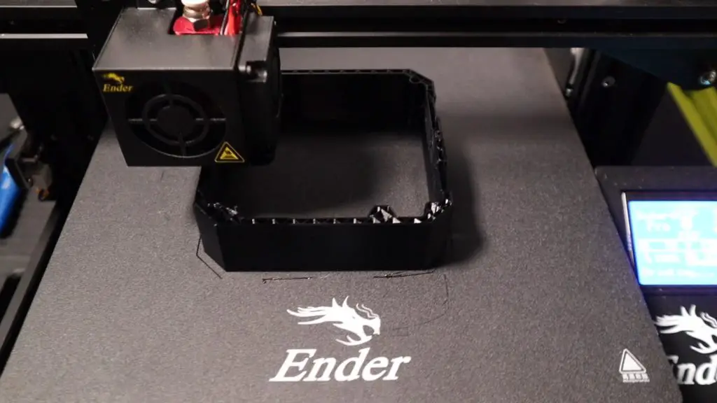
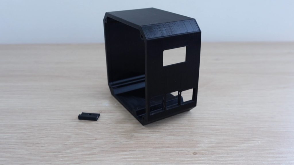
I 3D printed the Raspberry Pi 4 Desktop Case using Black PLA with a 0.2mm layer height and 15% infill. I also added print supports for the cutouts for the display and ports on the front. You’ll probably need to add these as well, which is easy to do in your slicing software. You’ll also need to print the small plastic display clamp.
Install The Raspberry Pi & Ice Tower
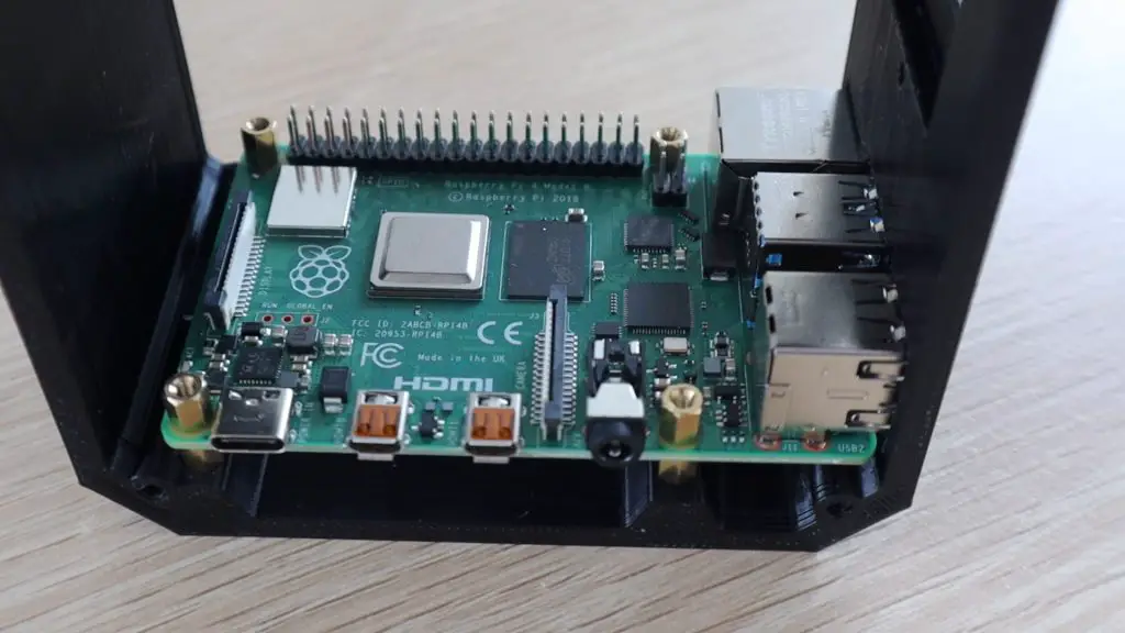
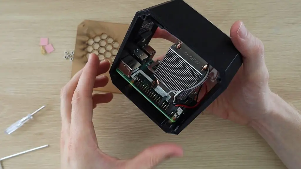
Now that the main body of the case is complete, let’s mount the Raspberry Pi into it. Start by screwing the brass standoffs into the holes in the base.
The holes for the brass standoffs are intentionally quite tight the first time you screw them in. You’ll likely need to use a small wrench or spanner to get them screwed in, you can also use some needle nose pliers if you don’t have a suitable size wrench.
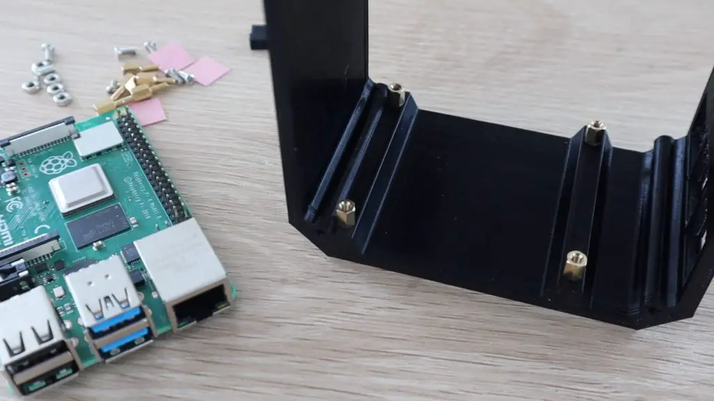
I’ve just changed the orientation of the screws and standoff mounts supplied with the Ice Tower so that they screw straight into the bottom of the case and don’t require and through holes. If you follow the Ice Tower installation manual, you’ll notice that the standoffs and screws are installed the opposite way around.
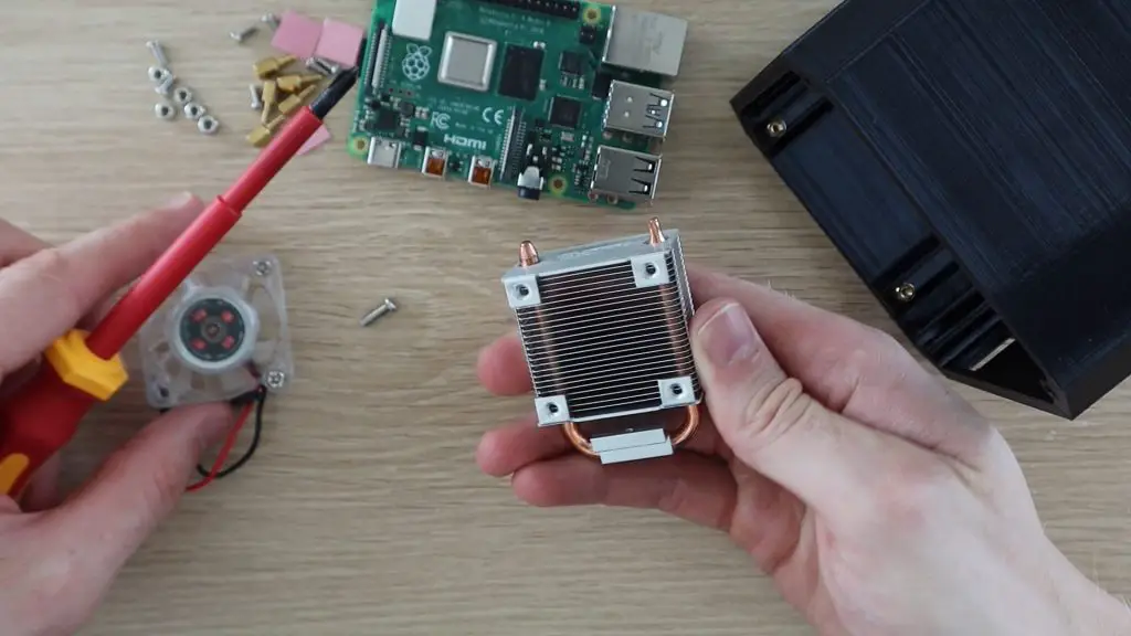
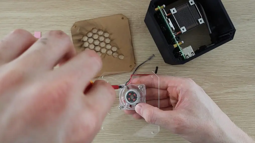
Next, we need to remove the fan from the Ice Tower so that we can attach it to the acrylic side panel. By moving the fan onto the side panel, we make sure that cool air is being drawn in from the outside of the case and then has to leave from the exhaust air vents on the opposite side.
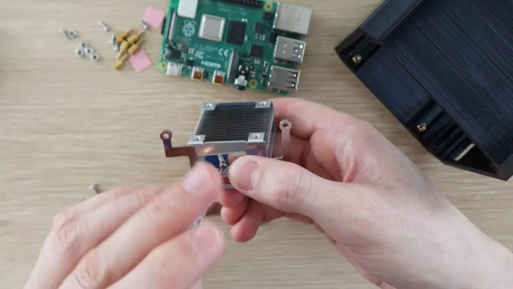
Add the support brackets to the bottom of the Ice Tower heatsink as per the instructions. Make sure that you follow the correct orientation of these.
Update – As a few people have pointed out, it’s easier to install the OLED display and the screw to hold it in place before putting the Ice Tower in.
Place the Raspberry Pi into position and then use the second set of brass standoffs, screwed into the bottom set, to secure it.
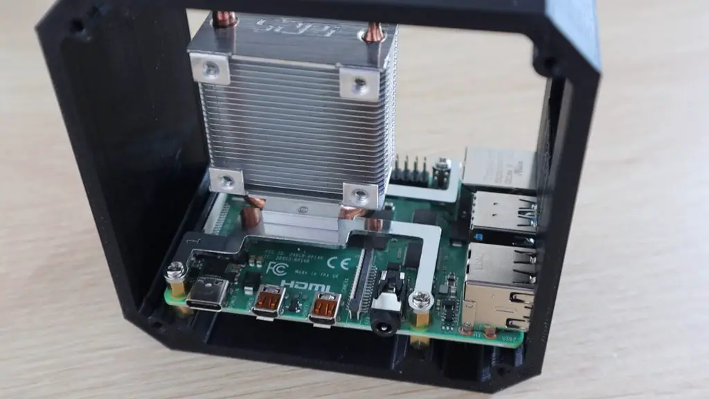
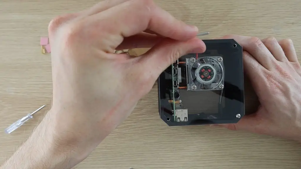
Stick the heat sink pad onto the Pi’s CPU and peel off the top layer of protective film. Position the Ice Tower heat sink onto the heat pad on the CPU and then secure it with the four screws into the brass standoffs.
Install The OLED Display
Now we need to install the OLED display onto the front panel. If your display came without the pins soldered into place, solder them onto the back of the display.
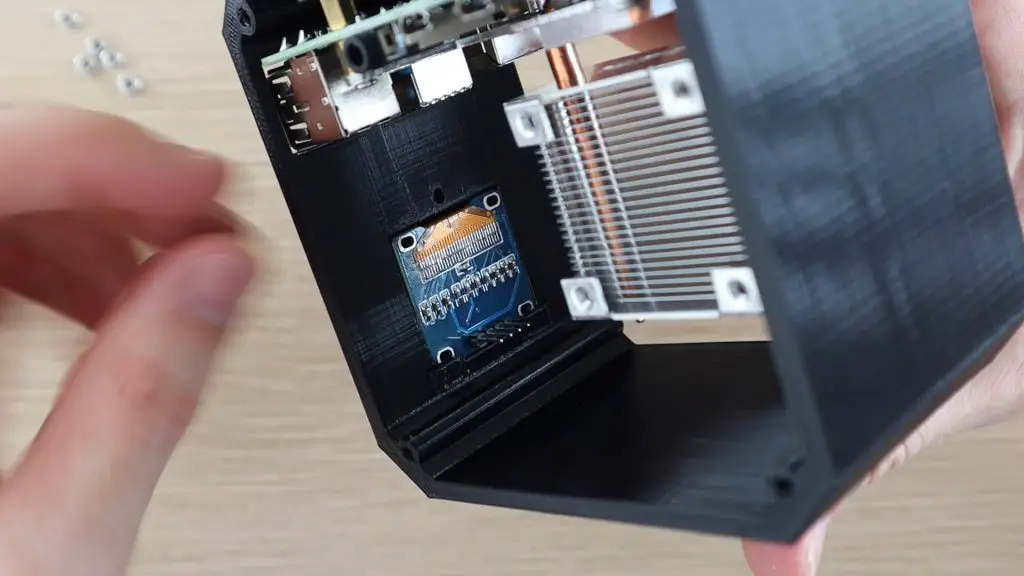
Slide the top edge of the display in under the plastic clips and then gently push it down into position in the cut-out.
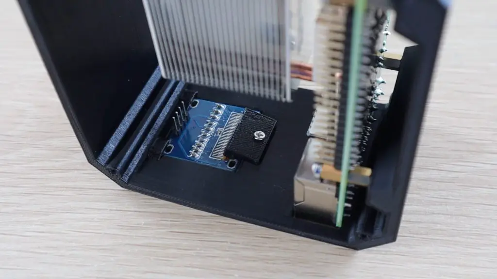
Use the 3d printed clamp to hold it in place with a small screw. You might need a flexible shaft or 90-degree screwdriver to tighten the screw.
Update – I’ve put together a detailed guide to connect and program the OLED display.
Don’t over-tighten the screw, the clamp just needs to gently hold the display in place. If you clamp it too tightly you might crack the glass on the display.
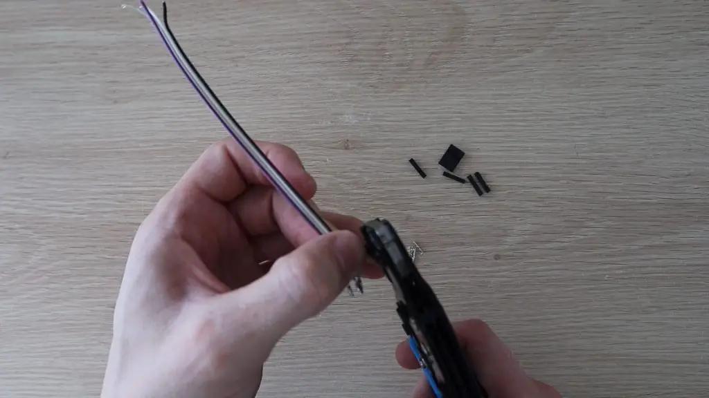
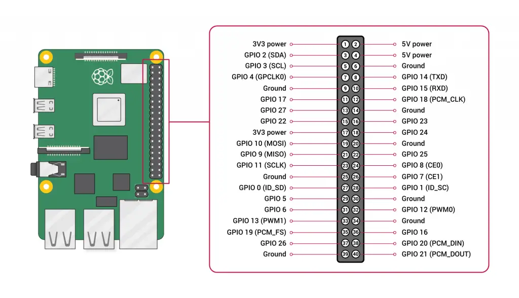
Now we need to prepare the wiring to the OLED display. You’ll need to make 4 connections to your GPIO pins, two for power and two for communication. I made up this short connector cable using some DuPont connectors and some ribbon cable. You can also use some female pin header strips or female breadboard jumpers to connect the display to the Pi.
Once your cable is made up, connect it to the back side of the display and then plug the leads into the GPIO pins as follows:
- GND to Pin14 Ground
- VCC to Pin1 3.3V Power
- SCL to Pin5 SCL (GPIO 3)
- SDA to Pin3 SDA (GPIO 2)
I’ve noticed that there are two versions of these OLED displays available and they have the power pins the opposite way around, one version has VCC and then GND and one GND and then VCC, so just make sure that you’re connecting power the correct way around for your display.
Make The Acrylic Sides
The internal parts of the case are now mostly done, so let’s make up the acrylic sides to close it up.
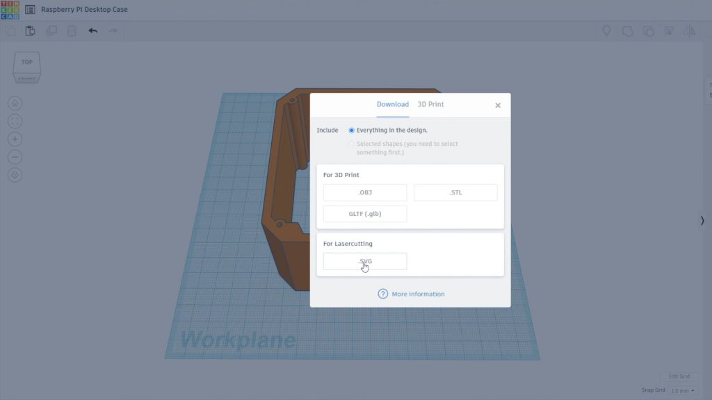
I started in Tinkercad again and positioned a block in the case roughly where the Ice Tower heat sink is going to be so that the holes for the fan are in the correct place on the side panels. I then exported the side profile of the case and heat sink to open up in Inkscape to draw the laser cutting profile.
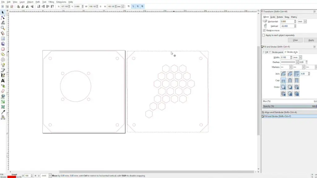
We need two sides, one with the fan for the inlet and one with some holes in it for the exhaust air.
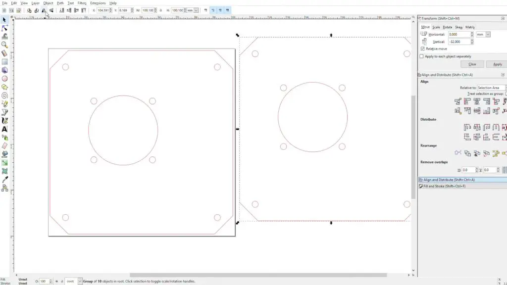
We can remove the inside edge profile as we only need the outline of the case and the screw holes. We need to add a hole for the fan and the four surrounding holes for the fan screws. We’ll also need to add cut-outs for the ports along the side of the Raspberry Pi.
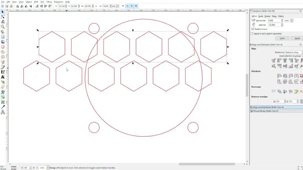
Next, I created a mirror of the fan side to the exhaust side and drew a hexagon pattern for the exhaust airflow.
If you’re not going to be laser cutting the sides and you’re cutting them out by hand, then replace these hexagon holes with circular drilled holes (Ø8mm) in the same area.
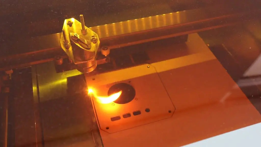
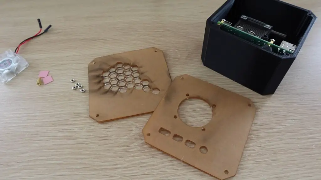
Now let’s get the sides cut out. I used 2mm clear acrylic for the side panels.
You can use a colour tinted or opaque acrylic as well if you’d like. A lot of the coloured sheets are only available in 3mm. This won’t really matter, you’ll just have thicker edges.
To mount the fan onto the side panel, you’ll need to press some M3 nuts into the pockets by the screw holes. It’s easiest to place the nut on a flat surface and then press the fan hole over the nut to push it into place. These are tight so that you don’t need to use a spanner to hold them when you tighten the screws.
If you want to re-use the fan screws, they’ll be too short to fit through the acrylic and fan and then into the nuts, you’ll need to press the nuts into the front (acrylic side) of the fan. You’re relying on the friction between the nut and the fan to hold it in place, but it works fine in this case as there isn’t much load on them.
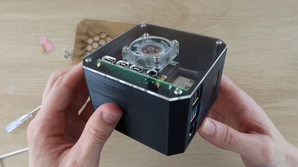
Screw the fan side panel onto the 3D printed case using four M3 x 8mm hex head machine screws.
The screws should be a bit tight as the inside of the holes aren’t threaded, most 3D printers can’t print such a fine thread.
Now plug the fan into the 5V supply on the Pi and then install the other side panel. The red wire to Pin 4 (5V) and the black wire to Pin 6 (Ground).
That’s it for the assembly, the Raspberry Pi 4 Desktop Case is now complete. We just need to get the OLED display working.
Programming The OLED Display
Update – I’ve put together a detailed guide to connect and program the OLED display.
To get the display working, we need to run a Python script. You’ll need to boot your Pi up to do this.
The Raspberry Pi communicates with the display using I2C communication, so you’ll also need to make sure that this is enabled in your preferences or do it through the command line by running:
sudo raspi-configThen select Interfacing Options, then I2C, then select Yes and then reboot the Pi with the following command:
sudo rebootYou’ll also need to ensure that the python-smbus and i2c-tools libraries are both installed. They should be by default, but it’s worth checking, by running the following commands:
sudo apt-get install python-smbus
sudo apt-get install i2c-tools
sudo pip3 install Adafruit_BBIO
While you’re at this stage, it’s also worth checking that your Pi is able to see your display. You can display a list of devices connected to the I2C bus by entering the following command:
sudo i2cdetect -y 1This should display an output similar to the below:
0 1 2 3 4 5 6 7 8 9 a b c d e f
00: -- -- -- -- -- -- -- -- -- -- -- -- --
10: -- -- -- -- -- -- -- -- -- -- -- -- -- -- -- --
20: -- -- -- -- -- -- -- -- -- -- -- -- -- -- -- --
30: -- -- -- -- -- -- -- -- -- -- -- -- 3c -- -- --
40: -- -- -- -- -- -- -- -- -- -- -- -- -- -- -- --
50: -- -- -- -- -- -- -- -- -- -- -- -- -- -- -- --
60: -- -- -- -- -- -- -- -- -- -- -- -- -- -- -- --
70: -- -- -- -- -- -- -- --
This indicates that a device has been detected and it’s address is 0x3c. If you don’t get anything showing up here then check your connections to your display and make sure that you’ve got I2C communication enabled on your Pi.
Don’t proceed with trying to program the display if you aren’t getting an address in this step. This means that the Pi isn’t able to see the display, and it won’t be able to display anything until it is.
Next, let’s have a look at the script and how to install it. This script is mostly based on one of the example scripts in the Adafruit Python Library for OLED display modules, with a few changes by Shakhizat Nurgaliyev to add the CPU temperature and change the format of the display.
# Copyright (c) 2017 Adafruit Industries
# Author: Tony DiCola & James DeVito
#
# Permission is hereby granted, free of charge, to any person obtaining a copy
# of this software and associated documentation files (the "Software"), to deal
# in the Software without restriction, including without limitation the rights
# to use, copy, modify, merge, publish, distribute, sublicense, and/or sell
# copies of the Software, and to permit persons to whom the Software is
# furnished to do so, subject to the following conditions:
#
# The above copyright notice and this permission notice shall be included in
# all copies or substantial portions of the Software.
#
# THE SOFTWARE IS PROVIDED "AS IS", WITHOUT WARRANTY OF ANY KIND, EXPRESS OR
# IMPLIED, INCLUDING BUT NOT LIMITED TO THE WARRANTIES OF MERCHANTABILITY,
# FITNESS FOR A PARTICULAR PURPOSE AND NONINFRINGEMENT. IN NO EVENT SHALL THE
# AUTHORS OR COPYRIGHT HOLDERS BE LIABLE FOR ANY CLAIM, DAMAGES OR OTHER
# LIABILITY, WHETHER IN AN ACTION OF CONTRACT, TORT OR OTHERWISE, ARISING FROM,
# OUT OF OR IN CONNECTION WITH THE SOFTWARE OR THE USE OR OTHER DEALINGS IN
# THE SOFTWARE.
import time

import Adafruit_GPIO.SPI as SPI
import Adafruit_SSD1306

from PIL import Image
from PIL import ImageDraw
from PIL import ImageFont

import subprocess

# Raspberry Pi pin configuration:
RST = None     # on the PiOLED this pin isnt used
# Note the following are only used with SPI:
DC = 23
SPI_PORT = 0
SPI_DEVICE = 0

# Beaglebone Black pin configuration:
# RST = 'P9_12'
# Note the following are only used with SPI:
# DC = 'P9_15'
# SPI_PORT = 1
# SPI_DEVICE = 0

# 128x32 display with hardware I2C:
disp = Adafruit_SSD1306.SSD1306_128_32(rst=RST)

# 128x64 display with hardware I2C:
# disp = Adafruit_SSD1306.SSD1306_128_64(rst=RST)

# Note you can change the I2C address by passing an i2c_address parameter like:
# disp = Adafruit_SSD1306.SSD1306_128_64(rst=RST, i2c_address=0x3C)

# Alternatively you can specify an explicit I2C bus number, for example
# with the 128x32 display you would use:
# disp = Adafruit_SSD1306.SSD1306_128_32(rst=RST, i2c_bus=2)

# 128x32 display with hardware SPI:
# disp = Adafruit_SSD1306.SSD1306_128_32(rst=RST, dc=DC, spi=SPI.SpiDev(SPI_PORT, SPI_DEVICE, max_speed_hz=8000000))

# 128x64 display with hardware SPI:
# disp = Adafruit_SSD1306.SSD1306_128_64(rst=RST, dc=DC, spi=SPI.SpiDev(SPI_PORT, SPI_DEVICE, max_speed_hz=8000000))

# Alternatively you can specify a software SPI implementation by providing
# digital GPIO pin numbers for all the required display pins.  For example
# on a Raspberry Pi with the 128x32 display you might use:
# disp = Adafruit_SSD1306.SSD1306_128_32(rst=RST, dc=DC, sclk=18, din=25, cs=22)

# Initialize library.
disp.begin()

# Clear display.
disp.clear()
disp.display()

# Create blank image for drawing.
# Make sure to create image with mode '1' for 1-bit color.
width = disp.width
height = disp.height
image = Image.new('1', (width, height))

# Get drawing object to draw on image.
draw = ImageDraw.Draw(image)

# Draw a black filled box to clear the image.
draw.rectangle((0,0,width,height), outline=0, fill=0)

# Draw some shapes.
# First define some constants to allow easy resizing of shapes.
padding = -2
top = padding
bottom = height-padding
# Move left to right keeping track of the current x position for drawing shapes.
x = 0


# Load default font.
font = ImageFont.load_default()

# Alternatively load a TTF font.  Make sure the .ttf font file is in the same directory as the python script!
# Some other nice fonts to try: http://www.dafont.com/bitmap.php
# font = ImageFont.truetype('Minecraftia.ttf', 8)

while True:

    # Draw a black filled box to clear the image.
    draw.rectangle((0,0,width,height), outline=0, fill=0)

    # Shell scripts for system monitoring from here : https://unix.stackexchange.com/questions/119126/command-to-display-memory-usage-disk-usage-and-cpu-load
    cmd = "hostname -I |cut -f 2 -d ' '"
    IP = subprocess.check_output(cmd, shell = True )
    cmd = "top -bn1 | grep load | awk '{printf \"CPU Load: %.2f\", $(NF-2)}'"
    CPU = subprocess.check_output(cmd, shell = True )
    cmd = "free -m | awk 'NR==2{printf \"Mem: %s/%sMB %.2f%%\", $3,$2,$3*100/$2 }'"
    MemUsage = subprocess.check_output(cmd, shell = True )
    cmd = "df -h | awk '$NF==\"/\"{printf \"Disk: %d/%dGB %s\", $3,$2,$5}'"
    Disk = subprocess.check_output(cmd, shell = True )
    cmd = "vcgencmd measure_temp |cut -f 2 -d '='"
    temp = subprocess.check_output(cmd, shell = True )

    # Write two lines of text.

    draw.text((x, top), "IP: " + str(IP,'utf-8'), font=font, fill=255)
    draw.text((x, top+8), str(CPU,'utf-8') + " " + str(temp,'utf-8') , font=font, fill=255)
    draw.text((x, top+16), str(MemUsage,'utf-8'), font=font, fill=255)
    draw.text((x, top+25), str(Disk,'utf-8'), font=font, fill=255)

    # Display image.
    disp.image(image)
    disp.display()
    time.sleep(.1)
You’ll need to download the original Adafruit example library from Github to get the setup complete by using these commands in your terminal:
sudo python -m pip install --upgrade pip setuptools wheel
git clone https://github.com/adafruit/Adafruit_Python_SSD1306.git
Open a new terminal window, then navigate to the library’s directory:
cd Adafruit_Python_SSD1306Install the library for Python 3:
sudo python3 setup.py installYou can then run the above stats.py file or the example stats.py file in the Adafruit directory, you’ll just get a slightly different display layout with the Adafruit example.
Change to the directory containing the stats.py script:
cd examplesExecute the script:
python3 stats.pyYou can test run the script to check that your display is working correctly and you don’t get any errors before setting it to run automatically.
To set the script to run automatically, you’ll need to find the script’s directory, then open crontab and add a line to run the script:
@reboot python3 /home/pi/stats.py &You’ll obviously need to change the directory /home/pi/ to reflect the directory where you have your script saved.
Don’t forget to add the & at the end, this tells the Pi to continue starting up and run the script in the background.
Reboot the Pi to automatically run the script and you should then see the stats shown on the OLED display when it starts up.

I’ve also made an Ice Edition of this case using white PLA for the case and a blue-tinted acrylic for the side panels. This Ice Edition Kit is available through my Etsy store.
Let me know if you like this Raspberry Pi 4 Desktop Case or what you’d do differently in the comments section.
Edit – Alternate Font Option for the OLED Display
Thanks for Richard Jelbert for finding an alternate font which looks much clearer than the default one.
To get this font to work, you’ll need to:
- Change the display size setting from 128 x 32 to 128 x 64. To do this you just need to comment out the 128 x 32 line and uncomment the 128 x 64 line a little below it:
# 128x32 display with hardware I2C:
disp = Adafruit_SSD1306.SSD1306_128_32(rst=RST)

# 128x64 display with hardware I2C:
# disp = Adafruit_SSD1306.SSD1306_128_64(rst=RST)- Download the font PixelOperator.ttf from https://www.dafont.com/pixel-operator.font and then place it into the script directory. You’ll then need to edit the below code by commenting out the initial font = Image… line and uncommenting the last line, changing ‘Minecraftia.ttf’ to your font and selecting a suitable font size. Richard has used font size 16.
# Load default font.
font = ImageFont.load_default()

# Alternatively load a TTF font.  Make sure the .ttf font file is in the same directory as the python script!
# Some other nice fonts to try: http://www.dafont.com/bitmap.php
# font = ImageFont.truetype('Minecraftia.ttf', 8)
Re-load the script and you should then get a much clearer text readout on your display.
Share This Guide
Wau! Greate jobe!
Looks amazing. I’d be willing to buy the 3D printed parts if someone wanted to print and sell them!
Thanks! Useful information!
The 3d files are .svg and the laser cutter files are .stl
It’s the other way around, the 3D print files are .stl 3d models and the laser cutting files are .svg 2d path files.
Me too, can someone please make it and sell it.
I am working on a manufactured version at the moment, there are a couple of minor changes that need to be made to suit the moulding.
Will this be a kit and/or just a finished product? Both are of interest but kit would be really fun to do with my kid! Beautiful job!
It would be a kit to some degree, most cases are. You would still need to assemble the ice tower, mount the OLED display, mount the Pi and then close up the case.
Do you think it would be possible to mount an SSD internally?
Not with this design, but I’m looking at how to integrate an SSD into a future case. It’s the cable to the USB port that is the problem.
I bet you COULD mount an SSD in that case, actually. Most 2.5″ SATA SSD drives are actually just a very small board on the inside of the plastic or aluminum casing. If you just opened the SSD casing and took the SSD board out, they’re quite small, so I think you might easily be able to mount one?
See 4:28 in this video to see what I mean:
https://youtu.be/lU4_wgot-gM?t=268
Yeah, the actual drive is pretty small, it’s just a pity the Pi doesn’t provide an easy (internal) way to connect them. Even with the drive inside the case, you’d still need to run a USB cable out of the case somewhere and to the front (or back) USB ports.
also, can you please include the file for the clamp? thanks
The clamp model is provided in the same download as the case model.
Great job nice project must try this out myself for sure.
2 things I would like to ask @Michael
Laser cut link is broke amazon has error can you fix link
Can you compile all this into a downloadable zip file /pdf guide for us that would be awesome
Thanks again
It seems the affiliate link for the k40 laser cutter is broken :/
Thanks JE, I’ve added an alternative. Unfortunately the suppliers of these usually only keep a few in stock and the product page gets pulled when they run out.
Can you please add a link to the screws and brass stand offs you use for the holes you designed to mount pie? Thanks so much
Hi Brandon, I used the screws and brass standoffs supplied with the Ice Tower, that’s why I haven’t listed them separately. They’re M2.5 screws and 6mm brass standoffs.
Hi Michael,
Thank you so much for this awesome guide to create a mini Raspberry Pi desktop! 🙂
I have managed to build it by following the steps in this article. The only problem that I’m facing is the acrylic cutting for the ports seems to be too small. I had to enlarge them to fit my plugs.
Thanks for the feedback Ginny. Yeah unfortunately cables all have different size connectors, so it’s difficult to find a balance between allowing enough space to fit all or most of them and not leaving big gaps around the connectors – which don’t look good.
Thanks Michael for your reply. Also I was wondering do you sell this item ? I’m going to try to do it all on my own but just in case it doesn’t work out I’m curious what you would charge to make it all ?
Hi Brandon, I’m busy looking at some manufacturing options for the case. Commercial 3D printing is still quite expensive and these take way too long to print on a home 3D printer.
Hi Michael,
Very nice job! I was wondering how hard it would be to rotate the board so that it can have a cleaner look on the front (just the OLED) and the USB/LAN ports on the back?
Again, congrats on the great looking case!
That should be difficult, the case is symmetrical, so the easiest would be to just move the display cutout to the back and make the back the front (turn it around).
Thank you!
What are the measurements for the acrylic parts and the 3d printed case, as I’m ordering them to be laser cut online and they require measurements.
The side profile is 100mm x 100mm, they probably just want to make sure their scaling is correct.
Could you please provide the final dimensions of each of the acrylic sides ? Thanks
They’re also 100mm x 100mm
È possibile acquistarlo, nella versione per PI v. 3?
Michael,
I tried to print this 3d case file tonight and ran into some issues. At 84% the print started print mid air on to nothing and so I was wondering if you have any reasons why I might have had problems with the stl. I’m printing on an ender 5 plus. The file came erected and in your video you show it laying sideways. I’m also wondering if you used supports. Could you possibly send me the profile of your cura print setup? Thanks for all your help on getting me across the finish line on this project.
Hi Brandon,
Yes, the intention is to print the case on its side, not upright. I’d assume that it most likely failed because there were no supports for the top flat section (if you printed it upright), so the top just spaghetti’s until the printer thinks it’s done. The printer settings in Cura should align with your particular setup, so I’m not sure that sending you the print file would work successfully either.
If it helps, used Creality Slicer, I turned the case onto its side (the 100mm x 100mm side profile laying flat on the bed) and then used the following settings – 0.2mm layer height, 0.8mm shell thickness, 15% infill, 15mm/s print speed, 210C print temp, 50C bed temp, support type – everywhere, platform adhesion type – none. I’m also using a 0.4mm nozzle and 1.75mm PLA filament.
Thanks again Michael the print turned out great. I’m on my 2nd one now it’s about an 8 1/2 hour print just so everyone else that is interested knows. Also it seems a lot of places that offer cut services for acrylic don’t have 2mm so I seen you said 3mm is fine do I need different screws?
That’s great! Yes, mine took around 8 hours to print as well.
3mm Acrylic is fine and you won’t need longer screws. M3 x 8mm screws will still give you around 4-5mm screwed into the case to secure the covers.
I printed on a Prusa Mk3 using the PrusaSlicer without supports with the Bottom flat against the print bed and had a half dozen flying strands under the narrow ledge. I used PETG and had a nice finish on the back and front using Hilbert fill pattern top and bottom.
I am struggling with the software as the Adafruit_GPIO package is not working for me on the RPi4 using the Raspberry OS. Any suggestions?
I’m impressed that the Prusa could print the top flat without supports and only a couple of flying strands!
For the OLED display, try running through the library installation steps outlined in this tutorial – https://maker.pro/raspberry-pi/projects/raspberry-pi-monitoring-system-via-oled-display-module
Hopefully this gets it working.
Michael,
Thanks for your patience with my questions. Are there any special print instructions for the oled bracket before I attempt to print it?
No problem at all. The clip is pretty small and straight forward, just print it with the largest flat side on the bottom and print it solid (100% infill).
I’ll provide my feedback once I get to that point I just ordered all the extra pieces now that I got the case printed.
The Adafruit library you link to is deprecated, and following your directions (both above and here in the comments results in “ModuleNotFoundError: No module named ‘Adafruit_BBIO'”
Suggestions?
sudo pip3 install Adafruit_BBIO
That got it working somewhat.
I see stuff on the display but the first two lines are blank, and the bottom two start with b’.
b’Mem: [data]
b’Disk: [data]
Also, the memory data runs off the right-hand side of the display.
Pretty cool little project. I was able to get the display up and running but have two issues I am trying to resolve. 1. I cannot get it to run the script automatically and after I changed the stats.py script it no longer displays the IP address. It has a line for it but the space is blank. Once I figure those issues out I think I will add these displays to my other PI’s.
I was able to resolve the missing IP address by eliminating this portion of the listed changes:
cmd = “hostname -I | cut -d\’ \’ -f1”
will be replaced by the following line:
cmd = “hostname -I |cut -f 2 -d ‘ ‘”
All of the other modifications were done and I got the perfect display. now to get ot to load on startup…
Hi Matthew,
Thanks for the update. I’ll have a look at this again, I had to edit that same line (to what you had originally) to get mine to display the IP address otherwise mine was blank.
Have you managed to get the display to load on startup? Remember to add the #!/usr/bin/python3 line to the beginning of your Python script, it may need to be changed depending on what you’re running it in.
I kind of gave up on it last night and have not started back yet. This is my first time building a system and running anything other than octoprint on a pi for my 3d printers. No coding experience or anything. Planned for this to be a little machine to teach myself some of this other world. All I have done so far is install the Raspberry pi OS and follow your guide. I will probably dive back into it tonight and see what I can figure out.
Can you do it for raspberry pi 3 b+ please? And 60×60 fan.
Tanks you
I also would love to have one for my 3B+
Hey Michael,
You mentioned that you are “looking into some manufacturing options” for this project/case. Do you have a mailing list or something where we could be updated about his process? Like, if you do a Kickstarter for the whole case setup (w/ or w/o a Pi 4), I would love to be notified via email so I could be one of the first to back it.
Thanks!
Hi Robin,
Yes, I’m hoping to have a Kickstarter launched in January. That’s a great idea, I’ll get a mailing list prepared so that you’re notified when it launches. I’ll send you the link shortly!
How much for the case if you made it?
I’m currently selling them on Etsy for around $49 including free international delivery, they’re out of stock at the moment but should be re-stocked soon.
Can you provide link for listing on etsy?
https://etsy.me/3ov1e6c
Can you provide a link to etsy listing?
hi Michael,
i have found a mistake in your skript. When commanding to display:
cmd = “hostname -I |cut -f 2 -d ‘ ‘”
you must add =
cmd = “hostname -I |cut -f 2 -d ‘='”
for the right command.
this shows the correct IP-address
Thank you for this amazing instruction, it works very well.
Thanks Stefan. I’ll add this as a note. Interestingly, the code was like you’ve stated when I got it and I had to change it to the way I have it to get the IP address to display on mine.
Hi, great job.
Are you planning maybe multiple versions? As someone suggested, a version without OLED display or with OLED on the other side to look sleeker? Different colors/materials to choose from (a semi-transparent bronze PETG case would look good)? Another cutout next to the 40pin header with a right angle adapter to be able to access GPIO without removing side the panel? (would this even work/fit – is there enough/not too much space between the header and the side panel?) Thank you and keep the great ideas/quality ratio 🙂
Filip from CZ
Thanks Filip,
Yes, I’ve been looking at a couple of different ideas and options. I’ll definitely post some updates on this page as they develop.
Thanks for the support!
Michael,
Thanks for the link I was curious if you would consider providing a listing for example just 3D printed parts not hardware and just the acrylic sides by themselves ?
For me that would be also interesting. Like only order the acrylic sides by themselves. I have a 3d printer and can print the case but unfortunately i do not have a laser cutter to cut the acrylic sides…
Hi Martin,
I’m looking into some shipping options for the side panels. At the moment the shipping accounts for around $10-$15 of the price, so having to pay around $20-30 for just the side panels seems quite expensive. If I can find a reasonably fast shipping option for a couple of dollars then it might be worthwhile.
That would be really great if that would be possible! I mean i do not mind paying around 20$-30$ as long as i somehow can get them :p But of course if there is a way to save on shipping cost then it would be even better!
Thanks for this great design!
I’d post up some pictures of what I did, but that’s not really an option.
So follow along in your mind’s eye:
I took the 3d models he has here for the sides, but decided that 2mm thick was a good bit thicker than I needed.
Then I made myself a border around the outside about 5mm wide, with “bumps” inward to circle the four holes for the screws to hold them on. I think of this as a illusionary “frame” to hold the windowed side on. From this I created a model about 0.4mm tall on the Z axis, and I subtracted that same model from the side. (I did a frame border around the fan holes as well.)
Then, I made a positive part of the fan holes and the air holes on the other side. (I use Tinkercad mainly, so you make things to delete them later).
I found a cool circuit board design on Google image search and converted it to an SVG. Sized it the way I wanted, then cut the parts for the fan holes, the air holes, AND the frames out of each of a pair of copies of that design. Dropped the designs’ heights down to a mere 0.2mm thickness and grafted it to the inside surface of each side.
So how I print this all as one piece is I print a frame (I used black PLA, same as the body) on the bed. I do not remove it. I change filament to clear transparent. I then print the side part but I have a filament change set at the height where the circuit board design starts. Then I switch to copper silk PLA. Oh, and I run 0.1mm layer heights to get everything as “solid” as possible in terms of color (more layers tends to reduce the bleed-through of different colors).
The result is a translucent window, with a frame around it and a neat little copper circuit board trace design on the inside. Can’t do that with a laser cutter.
Hi Buddy good job I’m gonna make one for myself. By the way pls correct SDA at blog
VCC to Pin1 3.3V Power
GND to Pin14 Ground
SCL to Pin3 SCL
SDA to Pin2 SDA
Pin 2 is 5v 🙂 someone can burn display
Hi Bülent,
These OLED display modules are designed with a voltage regulator on them, so they can run at 5V or 3.3V so that they work with 5V microcontrollers like Arduinos as well (at least all of the ones I’ve come across can run on either 5V or 3.3V). But yeah, you can plug it into any of the 3.3V pins as well.
This script does not run under python 3 and the libraries for adafuit have been depreciated and changed to work under python3. Is there any way you could update the script to run under 3 or 3.7?
ModuleNotFoundError: No module named ‘Adafruit_GPIO’
Disregard my last two post…I got i working…
Glad you managed to get it working Christian!
Ok, love the product. Really makes my raspberry pi feel more like a computer than a kit toy. I do have a problem though, i have zero line code and programming experience and i tried to follow the step by step instructions listed here:
https://maker.pro/raspberry-pi/projects/raspberry-pi-monitoring-system-via-oled-display-module
But unfortunately got lost when it came time to change the actual code command lines…..cant find the directory. Got the display to work but it still has the b’ prefixes. Any advice or help you can offer would be awesome. Again, thanks for the awesome case 🙂
Hi Jonathan,
The directory will be whatever directory was active when you downloaded the example code. This is usually home/pi/ but could be something else if you didn’t navigate back to this directory after doing something else.
Thanks for the great feedback!
Michael,
could you provide an .STL where the display cutout is on the other side, opposite the USB/LAN ports? I would like to have the display in the front but the USB/LAN ports on backs. Other then that, the case is really well made! Thanks!
Thanks Martin!
I’d have to modify the whole case and sides a bit to make that change. Unfortunately the pins on the back of the display clash with the Ice Tower if I just put the display on the other side.
Would that not be just a simply move of the OLED cutout from one side to the other side? It seems like that pins would exactly just fit above the Ice Tower, and if not they could be slightly bend which i would be ok with.
Anyway, i planned to use the low profile Ice Tower which would definitely not clash with the display pins. The question is now if it is just a simple move of the display cutout from side to the other one?
Oh, and also the display cutout could be slightly higher on the other side to prevent the display pins to clash with the Ice Tower.
Yeah you could use 90 degree pins or move the display up a bit.
Hi…
Astonishing job.
I’m wondering…
Can this setup be overclocked?
I know the ICE tower is pretty effective and the airflow seems neat, but I’m just noobie-questioning if adding a couple of fans on the back side (RGB, I hear you whisper? Why not if it fits) would make it cooler (for instance, the lower one pushing cool air in and the upper one pushing hot air out to add a cyclic airflow) or if it’s just overkilling it.
Hi Oscar,
The Ice Tower does a great job at keeping the Pi cool even with limited airflow. The airflow is just there to ensure that the air around the tower doesn’t start getting warm.
I’ve seen a few people ask about putting two fans on, it’s probably a bit counter-productive though. Pushing air into the case the way I’ve done pressurises the case slightly, the air then has to leave somewhere, which it does through the path of least resistance through the other side. By putting a fan on the other side, you’re just either going to limit the flow of the larger fan, or have them both running at the same flow rate as what one of them would have done by itself. The second fan isn’t going to double the volume of air moving through the first fan. You’d be better off adding two fans pushing air in or two fans pulling air out than having one in and one out.Does this make sense?
Hi Michael,
Happy New Year!
Would you please consider sharing the design on tinkercad? I love the design and have already set this this up for my pi 4, however I also have a few pi 3s kicking around so would like to slightly mod the design and also add a slightly larger screen.
I look forward to your response.
Many thanks and take care.
Jenny
Hi Jenny,
Happy New Year!
You should be able to upload the STL file back into TinkerCAD to make any changes you want to make. Always good to get some more use out of older Pis!
Michael, thank you for such a fun project. Saw this and another of your videos on a ‘best Raspberry Pi projects of 2020’ so congratulations! Would have happily bought one of these from your Etsy store but they were sold out, so I build one based on these instructions. Beautiful presentation. Very cool build. Love the design. Really appreciate that you included your Tinkercad process. As a newb, I wanted to share with others some of the challenges that I encountered:
My photos:
https://drive.google.com/drive/folders/1hmc9rdzRNmrea73uZVaFbBSoZ9YLlXqA?usp=sharing
1. Thank you for including files for 3D printing the sides. They were good place holders until the acrylic arrived. From an aesthetic standpoint the acrylic really makes it pop. The edges really highlight the RGB from the fan/cooler and make the whole look better.
1b. I used the 2mm acrylic and the micro HDMI connector BARELY makes the connection so 3mm might need a larger cut out for the HDMI port.
2. Definitely needed an SD card slot. They often go bad in RPi’s sometimes for no apparent reason. It was easy enough to upload your included .stl into Tinkercad and add a cutout. Still printed well after I downloaded the new .stl and sliced in Cura.
3. Ordered the oled’s from Amazon from your link., The screen size is slightly smaller than the cutout in the case. I’ll probably just put some black tape around it on the inside.
4. Also ordered the ribbon cable, but it’s not needed at all if you have four female/female wires. Now I have a nice supply of ribbon cable, though.
5. The screw to hold the display clamp made me question if life was worth living. Eventually just cut out a piece of plastic from some bubble packaging and used a short screw to hold it in place.
6. Ran across some videos where folks are using M.2 SSD’s as storage and boots…might be an idea to look at for modifications since a lot of comments seem to request this feature:
https://www.youtube.com/watch?v=Q1btyPoL0GI&feature=youtu.be
https://www.youtube.com/watch?v=HIYZwsc19CU&t=78s
7. Printed my case in Eryone Galaxy Sparkly Glitter Blue PLA at 0.2 on an Ender 3Pro
8. Used shorter screws to attach the sides
9. The brass standoffs were difficult to get to screw all the way into the PLA, but after it was assembled it occurred to me that I could have used a small socket from my ifixit tool kit.
10. Struggled to get the software to work for the display. Used these two Adafruit tutorials:
https://learn.adafruit.com/circuitpython-on-raspberrypi-linux/installing-circuitpython-on-raspberry-pi
https://learn.adafruit.com/monochrome-oled-breakouts/python-setup
Finally, the sudo pip3 install Adafruit_BBIO seemed to do the trick.
11. When I run the command “hostname -I” I get a return with my ip address and then MAC address. The regular expression in the code was a little unfamiliar to me, but it would write the MAC address which isn’t doesn’t really help when I want to SSH to the board. I changed the line in the code to read:
hostname -I |cut -f1 -d ‘ ‘”
now it just writes the ip address, ie the first ‘column’ in the return statement
12. the lines printed to the screen all bunched up at the top, so I modified my code to read:
draw.text((x, top+6),…
draw.text((x, top+18),…
draw.text((x, top+30),…
draw.text((x, top+42)….
puts a little space between the lines.
Thanks so much for this year’s holiday build.
MAH
Hi Maureen,
Thanks so much for sharing your experiences and suggestions, this is really useful and certainly gives a lot to think about. You case came out looking great, love the colour of the filament!
Just a couple of comments on your notes:
3. I’m not aware of any of these displays (the I2C ones) which are a different size. This is not to say you’re wrong at all, just unexpected. I’ll have to try order the one from Amazon and have a look. Does the top edge of the screen you’ve got not fit under the two clips at the top of the cutout? Although it might not fit properly, it should hold it in place a bit better. It looks like its behind these clips in your photos.
4. Yes this is a great solution. The kit’s I’ve been putting together are supplied with a 15cm female to female jumpers.
5. I seem to have made a lot of people upset with this clip! There are a couple of things I could have done differently if I wasn’t going to share the design. My worry through is that on different printers the tolerances are different, and therefore having an all “snap into place” design was likely to fail for most people.
6. I’m working on an SSD version now, most people seem to be keen for this addition.
10. Thanks for the additional tutorials. It seems like the Adafruit_BBIO install might solve the issue some users have had with running the script on python 3?
11. This one also seems to be odd to me. The code was originally written as you’ve got it and this displayed nothing for me. I edited it to display my IP address correctly. Some others have also told me that they had to edit the format to get theirs to display. I’m not sure if this is a Pi OS version, Python version or one of the libraries which causes this difference. It’s good to note non the less.
12. This might have to do with your display being smaller?
Thanks again for your great feedback and for taking the time to share your experiences!
Hi Maureen,
could you share what is the size and position for the SD card slot? Especially the size would be interesting for me since i am not sure how big it should so that i can grab the sd card.
Thanks!
Sure…I did mine in Tinkercad. Used a cube. I really sort of eyeballed it. The dimensions of the cut out are 12mm wide, 10 mm height. The length of the shape is 20mm but that doesn’t matter too much – it just needs to be long enough to cut through the side. The radius of the corners is 6.09 and the steps 12…these are variables for the cube that tinkercad allows. It is positioned 14mm from the bottom work surface. I placed it above where the angle starts at the bottom. If I did it again, I might try to place it a little bit lower and make it a little wider but it does work as is. I centered it by eye, but later remembered that in Tinkercad you can change the workplane to be the side of the case and then use the align function to center it. I didn’t post a link to my Tinkercad file because this is Michael’s property.
Hello, I am interested in buying your product but currently on the purchase page it appears as out of stock, do you plan to sell more units? Thanks in advance.
Hi Alpha,
I put some stock up each week, I just have to limit the numbers as I can only print a certain number per day. Check back in a couple of days and they should be back in stock again.
Michael,
Yes my screen module does fit nicely up under the ledge at the top…it had just gotten displaced while I was working with the micro HDMI situation. Here’s a pic of the screen lined up nicely:
https://drive.google.com/file/d/1tnAAaPSuQrBM3tXm-EQXuu8zaACSis8z/view?usp=sharing
There are gaps on either side. I get actual screen measurements of W 24.7 mm and H13.5 mm.
I’ve just had a look at the dimensions on the Amazon product page and compared it to yours and a couple of the OLED display’s I’ve got. All of the ones I’ve got are the same and are consistently a little larger than yours. It’s really weird that they’ve made a display that looks to be the same form factor as a pretty well established and common part but is actually a bit smaller. I guess I’ve got to be a bit more careful when recommending components! Sorry about that and thanks for letting me know.
MARTIN! Somehow I made a typo…my cut out is 20 x 10mm. Sorry. If I did it again, I’d make it 30 x 10.
Got it! Thank you very much!
Can i run with raspi 3b
The display will work, but you‘ll need to modify the case and side panels. The ports are different on the 3b
Hi Michael. Great job on the design of the case. I have made one for my son’s Minecraft server – just need to get the side panels cut now.
Regarding the OLED display, I did notice that the code example you gave used the wrong display version (128 by 32) and the display you link to is a 128 by 64. I changed the code to use disp = Adafruit_SSD1306.SSD1306_128_64(rst=RST) and then noticed that the default font went to half size so too small on this panel. After some searching it turns out that the default font only comes in one size so there is no way to double it. I then selected the font called PixelOperator.ttf from https://www.dafont.com/pixel-operator.font at fontsize 16 and it looks great and much clearer than the default font stretched over the 64 pixels of the y axis of the display.
Hope this helps!
Richard
Hi Richard,
Thanks for the tips on the display. Some others have pointed out that I had the incorrect display size set in the code, but I hadn’t thought about how this would affect the font size. I’ll go have a look at your font recommendation and try it out. Do you have a photo of what your display looks like now?
Hi Michael, yes the default font seems to be stretched over display so the definition is somewhat reduced. The lighting is tricky but I have put a photo of my adapted display code with the new font here: https://ibb.co/W5mxM9t
Thanks Richard, it definitely looks a lot better! I’ll put a note into the post about the alternate font.
That’s great – I can see your post now with my pic. Sorry the photo is not quite up to your normal high standard. Anyone using the new font will also have to play around with the spacing and padding further down in the code but it’s fairly easy to work out.
Having the the display in the case really helps debug and monitor activity on the Pi. I have also updated the display code to allow the 4th line on the display to be controlled by a different application. It accepts the text for the 4th line via a local UDP socket connection. It’s a few lines of python to include in the other application. My initial use case is showing the number of connected minecraft players. I’ll share the code on github when I get a moment.
Thanks for the additional info. That sounds really awesome, I’ve never thought to try display information from another application. If you do get around to sharing your code on Github, please drop the link here as well!
Has anyone converted your .py code to Arduino .ino as I am struggling with Python but feel more comfortable with the Arduino IDE.
Thanks
Hi Alan,
I’m not really sure what your intention is with converting it to Arduino. Are you wanting to run the code on an Arduino rather? Or are you just wanting to be able to edit the code in the Arduino IDE, but still use it on the Pi? I’ve got a few other projects which use this same OLED display on an Arduino, which may help you out. If you’re wanting to keep it doing the same functions on a Pi, then you’ll probably struggle with getting the information from the Pi and the automation of the script if not done in Python.
I know Python can be a be intimidating at first glance, but it’s actually significantly simpler to understand and code once you get the hang of it. I learned coding in C++ and I’m also still getting the hang of Python, but I’ve found it to be a whole lot simpler than C++.
Michele Thanks.
My intent was to edit using the Arduino IDE but I don’t see an appropriate HW description for the Raspberry Pi boards using the IDE so I am getting familiar with Python coding. Will keep plugging away. I am currently having trouble with a compilation error indicating the module Adafruit GPIO BBIO can’t be found in the Adafruit GPIO library. I’m not seeing any good links at Gethub. When I download (get) the Adafruit GPIO folder I don’t see anything with BBIO in the file names. Any suggestions?
Yeah I was also a bit apprehensive moving to Python, but you should get the hang of it quite quickly.
BBIO is another Adafruit library which you’ll need to install. Just Google installing the BBIO library and you should come right.
Also running the script in Python 2 instead of 3 should work if you want to try that?
Thank you Michael for this awesome Pi case.
For anyone else who is struggling with getting the OLED display to work, after many hours I’ve found this tutorial that worked for me:
https://www.raspberrypi-spy.co.uk/2018/04/i2c-oled-display-module-with-raspberry-pi/
Michael,
and Richard,
Thanks for the guide to change the font. For others, when I changed the font, I downloaded the .zip file from https://www.dafont.com/pixel-operator.font into the same folder/directory as my script. Then I unzipped it. When I uncommented this line: # font = ImageFont.truetype(‘Minecraftia.ttf’, 8), it only worked when I put the entire PATH to the .ttf font. ie:’ /home/pi/ PixelOperator.fft’ replaced ‘Minecraftia.ttf’. I actually used PixelOperator-Bold.
Thanks again for this project. I’m really enjoying playing around with a Python script like this.
Anyone able to provide replacement code to print the temperature in Fahrenheit instead of Celsius?
I could be wrong (I haven’t tried it), but the script just imports the temperature from your system, it doesn’t do any reformatting. So if your system is set to Fahrenheit then surely it would import the temperature in Fahrenheit?
Just as an update, I finally got my display running. I needed the GPIO_BBIO module and found this worked for me:
sudo apt-get update
sudo apt-get install build-essential python3-dev python3-pip -y
sudo pip3 install Adafruit_BBIO
I found it at:
https://pypi.org/project/Adafruit-BBIO/
I now off to learn about that font replacement.
Thanks for the excellent project.
My CPU load, line only reads 1 or 0. How do i get the % showing?
Thanks for your great work
Best regards
Joachim Sander Nielsen
The default code doesn’t show the % sign. You just need to add this into this line: draw.text((x, top+8), str(CPU,’utf-8′) + “% ” + str(temp,’utf-8′) , font=font, fill=255)
Ihave an issue with one of the examples in the /Adafruit_SSD1306/examples folder There is an example script called stats.py which output some system information to the 0.96 oled display.
When running the command python3 stats.py
I have an issues with the output,, i also see the following characters which should not be displayed i.e. the following
b’
\n’
‘
Can someone please advise if there is a solution for this.
Thanks
Hi Rav,
That’s not an issue with the code, that’s just what the code is written to display. The code provided on this page has those characters removed and some additional information added.
Some people have had an issue with the IP address not displaying with this version. This can be corrected by copying the IP address lines from the stats.py example.
Thanks Michael, I’ll give it a try
Hi Michael,
Tried your suggestion, copied relevant IP lines from the old stat.py to your version of stats.py. I am now seeing the IP Address but still getting extra characters –
IP: b’192.168.1.78\n’
All of the rest of the displayed information is correct.
Thanks
CPU Load always shows 1.00 or 0.00,
How can I fix this to show 5% – 11% – 50%?
The default Adafruit code and the edited code here should show the percentage as you’ve asked for it. What did you change in the code that it’s displaying 1.00 or 0.00?
Hello code you provided. I haven’t made any changes anywhere. It shows 1.00 – 2.00. What should I do for it to show as 10% – 35%
I want the CPU information to look like this picture
https://www.the-diy-life.com/wp-content/uploads/2021/01/Pi-Desktop-Case-Better-Font-954×1536.jpg?ezimgfmt=ng:webp/ngcb1
Without seeing your code or an image of what is being displayed on yours, it’s difficult to say. I can’t see a reason why yours would display something different if you’ve used the same code (without editing it) and the same size display.
Thank you very much for this tutorial. I used it as the base to make my own pi case. Here’s a link if you’re interested https://imgur.com/gallery/5uBJEC9
Your case looks great!
Thank you very much! By far the hardest part was getting getting a buck converter with enough amps to power the pi from the 5v and ground pins, the ssd, and all the leds from.
Michael I found a different take of the OLED python code that looks really good and does some different displays. The link is :https://github.com/UCTRONICS/U6144_SSD1306
Thanks for sharing this. Do you have any images of what the display looks like? There aren’t any links on GitHub (or at least that I was able to see)
https://youtu.be/hBBf6gIlap0
Uctronics version they use on all their pi4 rack mounts and cases with oleds.
https://youtu.be/hBBf6gIlap0
This is a video of the Uctronics case, and they use that oled version on all their p4 rack mount stuff too.
Awesome, I’ll have a look at it.
Where can I buy this in white?
The white cases are currently out of stock, they should be available again in the next few days.
Do you have a link I can check every few days?
Hi great work. Ive bought your updated files for my 2 raspi 4S. But i was wondering just to show them off a lot more is there a way to have a powered glow cable inside aswell. So it kind of looks like the real ones.
Again great work.
Mick
I haven’t seen powered glow cables that small, but if you could find ones which run on 5V or 3.3V then they would be quite easy to add.
Is your OLED code compatible with Twister OS for the Pi 4?
I haven’t tried the code on Twister OS but I don’t see any reason why it wouldn’t work, you might need to install one or two additional libraries.
I haven’t got the OLED display to be detected by the pi. Running i2cdetect -y 1 returns an empty table of dashes. I’ve made sure my pins are connected right and enabled the I2C interface but the Pi still can’t detect it. Could the OLED display be a dud? It’s still a nice case but its a shame its not working properly
If the table comes up blank it usually indicates faulty wiring. If you’re sure the wiring is correct then the display is likely damaged, although this often happens if the wiring wasn’t done correctly at some stage. These displays don’t have reverse polarity protection, so if the positive and negative are connected the wrong way around then they most often get damaged.
Would it be possible to have the acrylic drawing file with the relative dimensions and center distances to be able to make it with a cnc cutter? Thanks
Hi, great project!
However there needs to be access to the sd card without tearing the entire assembly apart.
Also maybe a slot on the exhaust side for extending the GPIO bus outside the case.
Any chance to put ssd inside ?
Cheers
There is one coming soon for a SSD.
any idea how long?
I really woukd like to buy your case, very nice job!
Like the design.
Is it possible to mount the display on the other side , for a cleaner look.
So the cables are at back and the display at the front.
Hi Michael, when setting up the Oled display configuration on the latest raspberry pi os 32bit there is an issue with the following command – sudo pip3 install Adafruit_BBIO
Lots of errors and red text
Can you check and advise please
Thanks
Hi Rav,
Yes it seems like some dependencies or libraries have been removed from Bullseye.
I’m working on a solution which I should be able to get published this weekend. I’ve just got it running on my Pi. Unfortunately it is quite different to the original process, but it’ll be quicker to do.
Thanks Michael for all your excellent work, please let me know when you publish the fix
Thanks Michael for all your excellent work
Look forward to the fix
Here’s the update – https://www.the-diy-life.com/add-an-oled-stats-display-to-raspberry-pi-os-bullseye/
Michael, thanks for the updated instructions to get the OLED Dsiplay working
Ruunning stats.py in the OLED_Stats folder works fine. If however you try to
run stats.py using the following command it doesnt work
python3 /home/pi/OLED_Stats/stats.py
You get the following error
pi@raspberrypi:~ $ python3 /home/pi/OLED_Stats/stats.py
Traceback (most recent call last):
File “/home/pi/OLED_Stats/stats.py”, line 41, in
font = ImageFont.truetype(‘PixelOperator.ttf’, 16)
File “/usr/lib/python3/dist-packages/PIL/ImageFont.py”, line 852, in truetype
return freetype(font)
File “/usr/lib/python3/dist-packages/PIL/ImageFont.py”, line 849, in freetype
return FreeTypeFont(font, size, index, encoding, layout_engine)
File “/usr/lib/python3/dist-packages/PIL/ImageFont.py”, line 209, in __init__
self.font = core.getfont(
OSError: cannot open resource
don´t work :/
pi@octopi:~ $ sudo python -m pip install –upgrade pip setuptools wheel
/usr/bin/python: No module named pip
pi@octopi:~ $
This tutorial is written for Raspberry Pi OS – it hasn’t been tested on other operating systems (like Octopi). These might be missing libraries or dependencies that this script relies on in order to run.
Hi Micheal, out of curiosity why do all these stats displays use CPU load instead of usage? I understand what the load number means, but it’s always weird to me that most other stat monitors eg; aida64, mobro, etc…. use usage instead of load. I ended up modding my script to get the idle cpu percent, and subtracting it from 100 to get the usage ( since there’s no easy way to get the total usage). Do you know what makes load preferable? Eithet way thank you.
Hi Knox,
I think it’s just the most accessible metric – Linux typically reports CPU load rather than utilisation and these scripts generally just pull the data directly from these utilities. The monitors you’ve mentioned are all windows based, which reports metrics differently to Linux.
As to what makes load preferable – I don’t think it is for single board computers like the Pi, but it’s easier to use/understand for large multi-core and multi-CPU computers/servers.
Ok, I see how that makes sense for larger multi-core and multi-CPU computers/servers. Actually with those and linux in mind it makes more sense why load would be preferrable. Thank you for your input!
This is a great project! I’m going to try it out.
Great post, Michael! Love this case.
In case anyone else is running into package deprecation issues, I’ve put together an updated setup.py script (https://gist.github.com/rosscm/393d090367df82497ceaca301e51e7cc) that’s adapted to Adafruit’s newer CircuitPython libraries. To note, I’ve tested this on a 4GB RPI4B running Raspbian GNU/Linux 11 armv7.
Hi Catherine, try my more up to date script – https://github.com/mklements/OLED_Stats
Ah, somehow missed this one. Thanks!
Hi Michael,
I have a Raspi 4 with Bookworm
and got your kit, but I had to run the script with python3.11-venv and
luma.oled script worked. The whole thing starts automatically with a crontab –e entry. @reboot python3 /home/pi/stats.py &
Greetings Udo
To get rid of the extra characters b’ \n etc, add universal_newlines=True
IP = subprocess.check_output(cmd, shell = True, universal_newlines=True)
Great job! There would also be a lipo battery with charger and a complete set. I just don’t have the fan backlight working, in the test, everything is fine… but after turning it off, there is no backlight, I can’t figure it out..
Bonjour Michael,
Merci beaucoup pour les informations de configuration de l’écran.
Maintenant cela fonctionne sans problème.