Today I’m going to be looking at adding AI line and object tracking to my previously built obstacle avoiding robot using a Huskylens.
A Huskylens is a standalone sensor with a couple of preconfigured recognition algorithms that allow you to easily add AI powered machine vision to your Raspberry Pi and Arduino projects.
It’s got built in object tracking, face recognition, object recognition, line tracking, colour detection and tag recognition and the best part is that it doesn’t require any internet connection to run. All of the processing is done locally on the Huskylens.
Here’s a video of the modifications done to the robot car as well as the car following lines and tracking objects, read on for the write-up and code:
What You Need To Build Your Own AI Powered Robot Car
- Arduino Uno – Buy Here
- L293D Motor Driver Shield– Buy Here
- Huskylens – Buy Here
- 4 x Geared DC Motors & Wheels – Buy Here
- 9-12V Battery Pack
- 8 x M3 x 15mm Socket Head Screws – Buy Here
- Ribbon Cable – Buy Here
- Header Pins – Buy Here
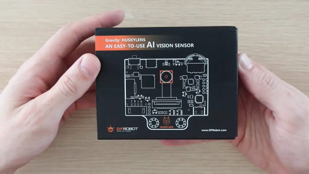
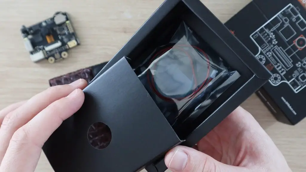
Unpacking The Huskylens
This Huskylens was sent to me by DF Robot to try out and share with you.
The Huskylens comes well packaged in a black bubble wrap sleeve within a two compartment box. Measuring just 52mm x 44.5mm, it’s smaller than an Arduino Uno or Raspberry Pi, it’s about the same size as a Micro:bit.
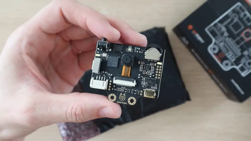
The device has two primary inputs. A multifunction menu selector and then a learn button, which allows you to select and learn new objects, faces and tags directly on the built-in 2-inch display. So you don’t need a PC with you to change modes or select different tracking objects.
An OV2640 2.0 Megapixel Camera on the front is the Husklen’s “eye”.
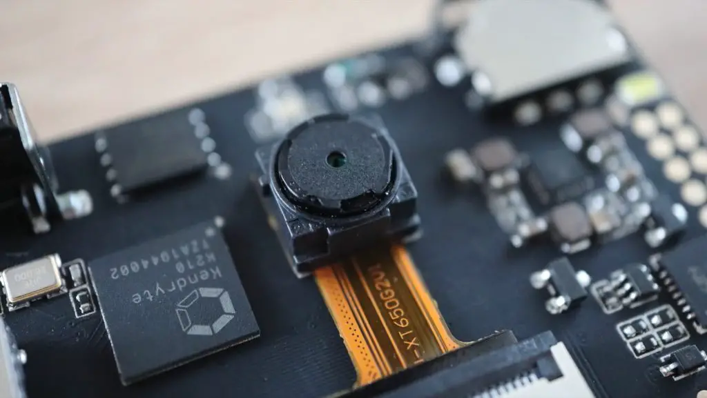
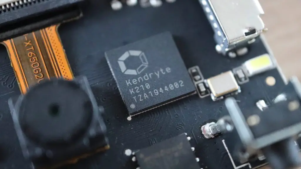
It uses a Kendryte K210 AI chip to run a neural network, which results in pretty impressively fast learning and recognition. Even with relatively fast-moving objects.
In the second compartment in the box you’ve got a mounting bracket, some screws and the cable to connect it to a microcontroller.
One thing that’s worth noting is that the included cable has female Dupont/jumper connectors on it. This makes it directly usable with a Raspberry Pi, which has male GPIO pins, but you’ll need to make up an adaptor to use it with an Arduino Uno or LattePanda which typically have female pins.
The Huskylens runs on 3.3-5V and consumes around 320mA at 3.3V or 230mA at 5V, so its perfect for battery powered projects as well.
Adding The Huskylens To The Robot Car
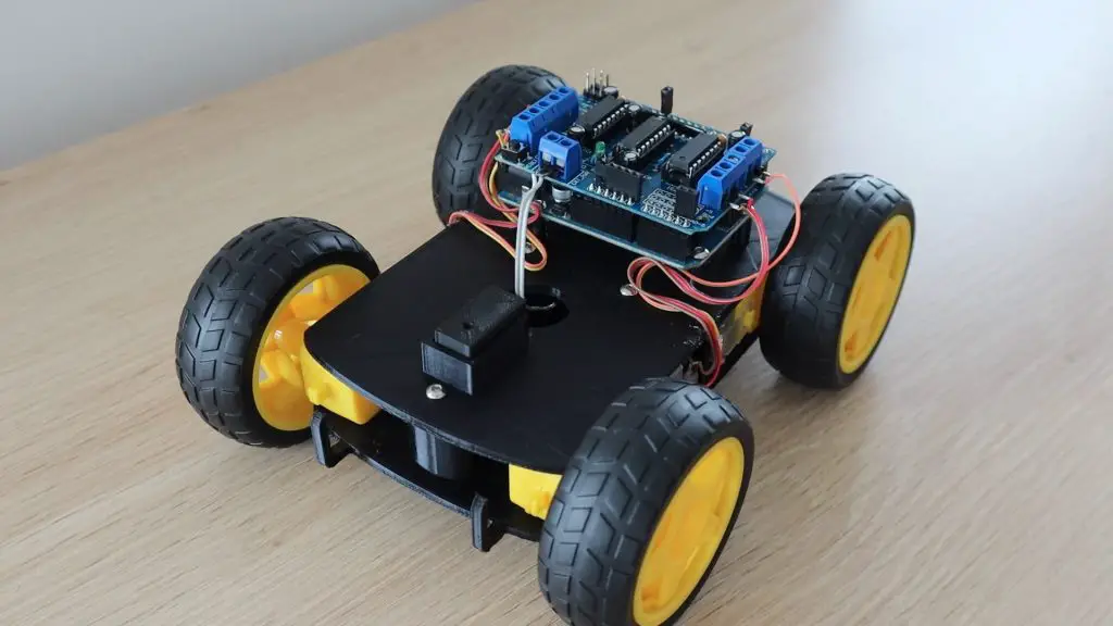
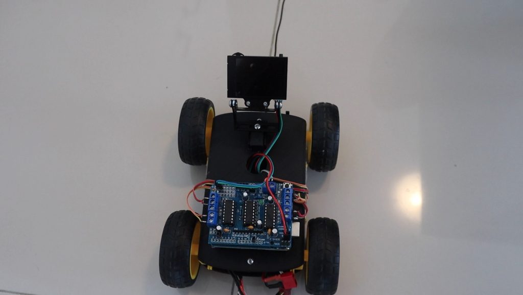
I’m going to be installing the Huskylens in place of the servo and ultrasonic sensor on the robot car which I built previously. Visit the previous build guide for the 3D print files for the car as well as assembly instructions, obviously leaving out the servo and ultrasonic sensor.
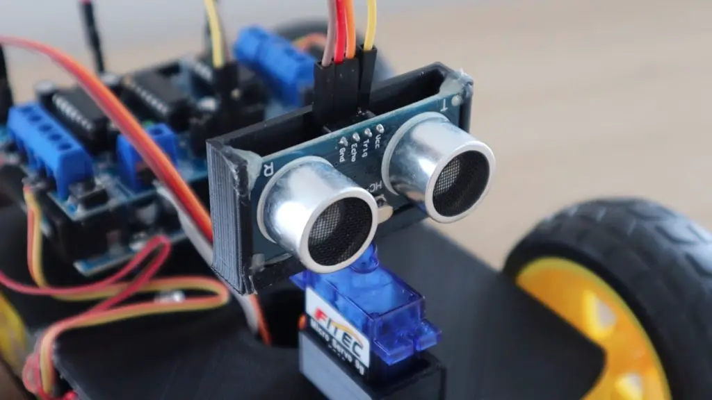
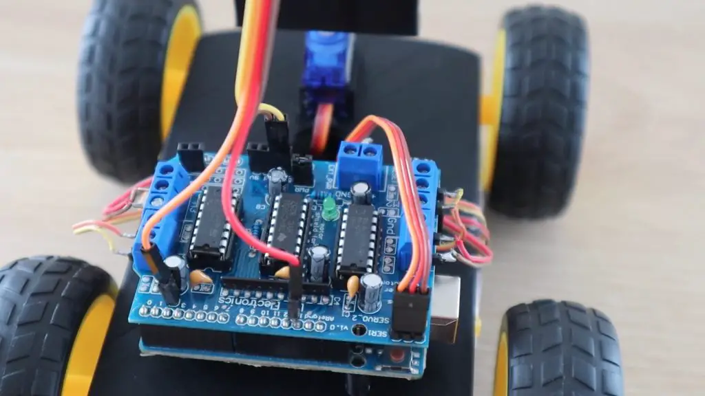
The car uses an Arduino Uno and a dual L293d motor driver shield to drive four wheels through some geared motors.
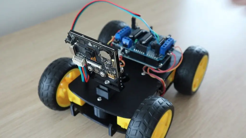
I’ll be mounting the Huskylens onto the bracket which is supplied with it. The bracket is somewhat universal in that it’s got a mounting pattern which could be fixed with a single screw, two screws or mounted onto a servo arm.
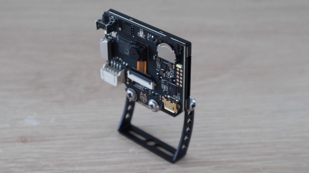
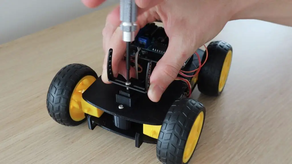
I’ve 3D printed a small adaptor block to fit into the servo holder on the robot car to screw the bracket into. I just glued this bracket into place using a glue gun.
I secured the bracket using a single M3x8mm screw through the centre hole.
The Huskylens can communicate using I2C or SPI communication, I’m going to be using I2C because these pins are still available on the motor driver shield. Just like any other I2C device, there are four connections to be made, two for power and two for communication.
I used the GND and 5V pins from one of the servo outputs and then connected the SDA and SCL wires to A4 and A5 respectively.
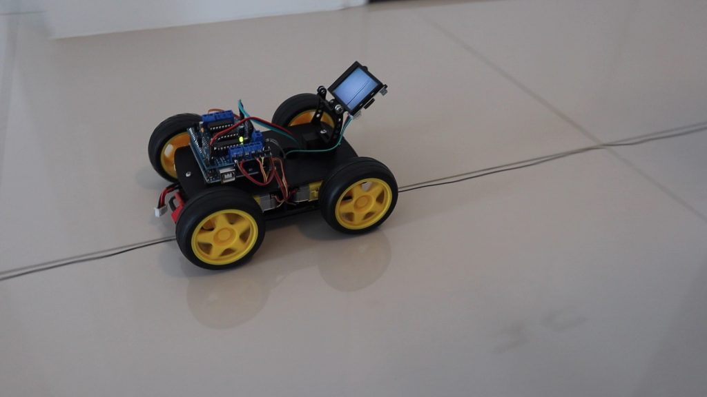
Now that it’s installed, let’s power it up and have a look at the line and object tracking functions.
Experimenting With Line Tracking
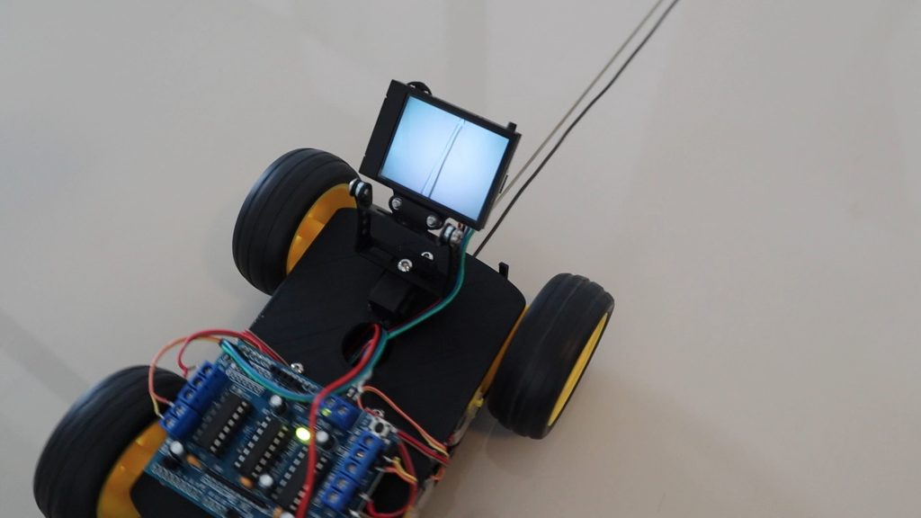
We’ll start by powering up the Huskylens and switching it to line tracking mode.
I’ve drawn a black arrow on a piece of paper, so let’s see how well it is able to pick it up.
We first need to point the crosshair in the centre at the line and then press the learn button to tell the Huskylens that this is the type of line it needs to follow.
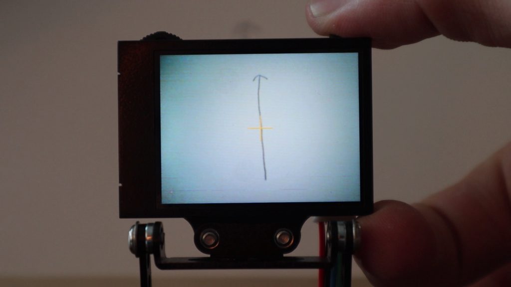
You’ll then see it recognise the line and overlay a blue arrow which follows the line around on the display.
The Huskylens is actually impressively fast when tracking a line and picking up direction changes, even when the line is removed and then brought back into the field of view.
I adapted the code from the obstacle avoiding robot to use the data from the Huskylens to follow a black line drawn on the floor using the Huskylens Line Tracking example by Angelo Qiao. There are some functions that have been carried over from the obstacle avoiding robot that are not used in this code but might be useful for future adaptations.
//The DIY Life
//Michael Klements
//16/04/2021
//Huskylens Line Tracking Robot
//Adapted from Huskylens Line Tracking example by By [Angelo qiao](Angelo.qiao@dfrobot.com)

#include "HUSKYLENS.h"                            //Import the required libraries
#include "SoftwareSerial.h"
#include "PIDLoop.h"
#include <AFMotor.h>

AF_DCMotor rightBack(1);                          //Create an object to control each motor
AF_DCMotor rightFront(2);
AF_DCMotor leftFront(3);
AF_DCMotor leftBack(4);

byte motorSpeed = 60;                             //The maximum motor speed
int motorOffset = 15;                             //Factor to account for one side being more powerful
int turnSpeed = 50;                               //Amount to add to motor speed when turning
int leftSpeed = 0;                                //Variables to keep current left and right motor speeds
int rightSpeed = 0;

PIDLoop headingLoop(120, 0, 0, false);            //Set up PID control for the heading, only P used for now
HUSKYLENS huskylens;                              //Create a Huskeylens object
int ID1 = 1;                                      //We're tracking recognised object 1

void printResult(HUSKYLENSResult result);

void setup()
{
  Serial.begin(115200);                                         //Start serial communication
  Wire.begin();                                                 //Begin communication with the Huskeylens
  while (!huskylens.begin(Wire))
  {
      Serial.println(F("Begin failed!"));
      Serial.println(F("1.Please recheck the \"Protocol Type\" in HUSKYLENS (General Settings>>Protol Type>>I2C)"));
      Serial.println(F("2.Please recheck the connection."));
      delay(100);
  }
  huskylens.writeAlgorithm(ALGORITHM_LINE_TRACKING);            //Switch the algorithm to line tracking.
  rightBack.setSpeed(0);                                        //Set the motors to the motor speed, initially all 0
  rightFront.setSpeed(0);
  leftFront.setSpeed(0);
  leftBack.setSpeed(0);
  moveForward();                                                //Start the motors
  accelerate();                                                 //Accelerate to the set motor speed
}

void loop()
{
  int32_t error;
  if (!huskylens.request(ID1))                                  //If a connection is not established
  {
    Serial.println(F("Check connection to Huskeylens"));
    leftSpeed = 0;
    rightSpeed = 0;
  }
  else if(!huskylens.isLearned())                               //If an object has not been learned
  {
    Serial.println(F("No object has been learned"));
    leftSpeed = 0;
    rightSpeed = 0;
  }
  else if(!huskylens.available())                               //If there is no arrow being shown on the screen yet
    Serial.println(F("No arrow on the screen yet"));
  else                                                          //Once a line is detected and an arrow shown
  {
    HUSKYLENSResult result = huskylens.read();                  //Read and display the result
    printResult(result);

    error = (int32_t)result.xTarget - (int32_t)160;             //Calculate the tracking error
    headingLoop.update(error);                                  //Perform PID control on the error

    leftSpeed = headingLoop.m_command;                          //Get the left side speed change
    rightSpeed = -headingLoop.m_command;                        //Get the right side speed change

    leftSpeed += motorSpeed;                                    //Calculate the total left side speed
    rightSpeed += (motorSpeed-motorOffset);                     //Calculate the total right side speed
  }
  Serial.println(String()+leftSpeed+","+rightSpeed);
  leftFront.setSpeed(leftSpeed);                                //Set the new motor speeds
  leftBack.setSpeed(leftSpeed);
  rightFront.setSpeed(rightSpeed);
  rightBack.setSpeed(rightSpeed);
}

void accelerate()                                 //Function to accelerate the motors from 0 to full speed
{
  for (int i=0; i<motorSpeed; i++)                //Loop from 0 to full speed
  {
    rightBack.setSpeed(i);                        //Set the motors to the current loop speed
    rightFront.setSpeed(i);
    leftFront.setSpeed(i+motorOffset);
    leftBack.setSpeed(i+motorOffset);
    delay(10);
  }
}

void decelerate()                                 //Function to decelerate the motors from full speed to zero
{
  for (int i=motorSpeed; i!=0; i--)               //Loop from full speed to 0
  {
    rightBack.setSpeed(i);                        //Set the motors to the current loop speed
    rightFront.setSpeed(i);
    leftFront.setSpeed(i+motorOffset);
    leftBack.setSpeed(i+motorOffset);
    delay(10);
  }
}

void moveForward()                                //Set all motors to run forward
{
  rightBack.run(FORWARD);
  rightFront.run(FORWARD);
  leftFront.run(FORWARD);
  leftBack.run(FORWARD);
}

void stopMove()                                   //Set all motors to stop
{
  rightBack.run(RELEASE);
  rightFront.run(RELEASE);
  leftFront.run(RELEASE);
  leftBack.run(RELEASE);
}

void turnLeft(int duration)                                 //Set motors to turn left for the specified duration then continue
{
  rightBack.setSpeed(motorSpeed+turnSpeed);                 //Set the motors to the motor speed
  rightFront.setSpeed(motorSpeed+turnSpeed);
  leftFront.setSpeed(motorSpeed+motorOffset+turnSpeed);
  leftBack.setSpeed(motorSpeed+motorOffset+turnSpeed);
  rightBack.run(FORWARD);
  rightFront.run(FORWARD);
  leftFront.run(BACKWARD);
  leftBack.run(BACKWARD);
  delay(duration);
  rightBack.setSpeed(motorSpeed);                           //Set the motors to the motor speed
  rightFront.setSpeed(motorSpeed);
  leftFront.setSpeed(motorSpeed+motorOffset);
  leftBack.setSpeed(motorSpeed+motorOffset);
  moveForward();
}

void turnRight(int duration)                                //Set motors to turn right for the specified duration then continue
{
  rightBack.setSpeed(motorSpeed+turnSpeed);                 //Set the motors to the motor speed
  rightFront.setSpeed(motorSpeed+turnSpeed);
  leftFront.setSpeed(motorSpeed+motorOffset+turnSpeed);
  leftBack.setSpeed(motorSpeed+motorOffset+turnSpeed);
  rightBack.run(BACKWARD);
  rightFront.run(BACKWARD);
  leftFront.run(FORWARD);
  leftBack.run(FORWARD);
  delay(duration);
  rightBack.setSpeed(motorSpeed);                           //Set the motors to the motor speed
  rightFront.setSpeed(motorSpeed);
  leftFront.setSpeed(motorSpeed+motorOffset);
  leftBack.setSpeed(motorSpeed+motorOffset);
  moveForward();
}

void printResult(HUSKYLENSResult result)                    //Display the results on the serial monitor
{
    if (result.command == COMMAND_RETURN_BLOCK)
    {
        Serial.println(String()+F("Block:xCenter=")+result.xCenter+F(",yCenter=")+result.yCenter+F(",width=")+result.width+F(",height=")+result.height+F(",ID=")+result.ID);
    }
    else if (result.command == COMMAND_RETURN_ARROW)
    {
        Serial.println(String()+F("Arrow:xOrigin=")+result.xOrigin+F(",yOrigin=")+result.yOrigin+F(",xTarget=")+result.xTarget+F(",yTarget=")+result.yTarget+F(",ID=")+result.ID);
    }
    else
    {
        Serial.println("Object unknown!");
    }
}Let’s upload the code and see how well it works.
I’ll start by pointing the Huskylens on the front of the car downward so that it’s looking at the ground just ahead of the car.
I’ve drawn lines on the floor, trying to keep near the grout lines in the tiles so that it hopefully doesn’t get confused. I’ve also put some masking tape on the lines leading away from the turns so that it follows the turns and ignores the grout lines leading on from the turn.
Here are some images of the car following the line. It’s best to watch the video at the begining of the guide to see the line tracking feature running.
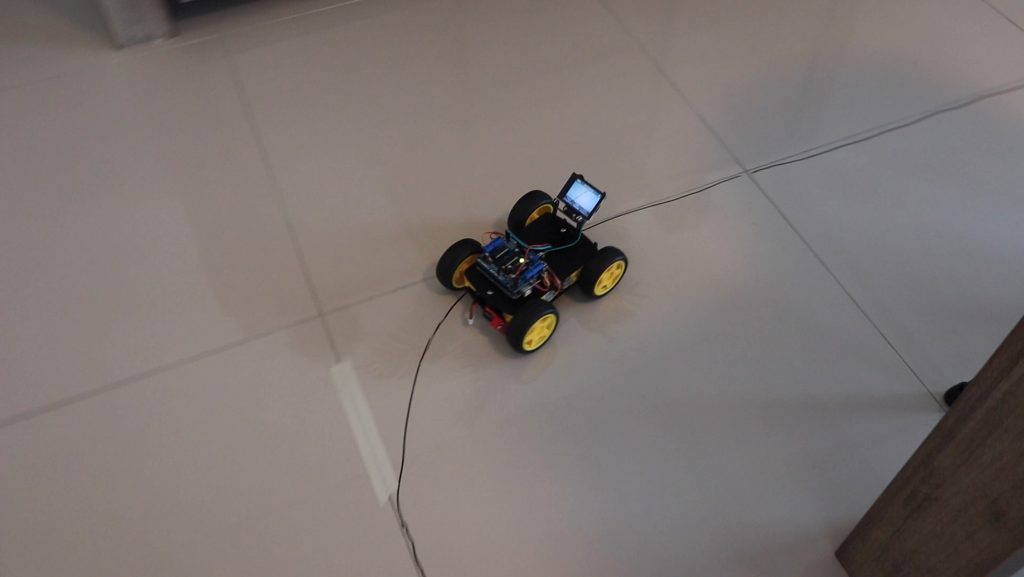
Overall, the line tracking feature worked pretty well. The Huskylens is responsive enough that the car starts making adjustments to its direction as soon as the line starts drifting off centre or changes direction, so it’s able to track the line with a bit of speed as well. It only veered off course a couple of times during testing and these all occurred when the wheels slipped on the smooth tiled floor.
The limitation to the speed is probably more to do with the actual motors than with the Huskylens. These geared motors are really cheap and low quality, so the driver has a hard time controlling the speed accurately.
Experimenting With Object Tracking
Now that we’ve tried out line tracking, let’s try object tracking.
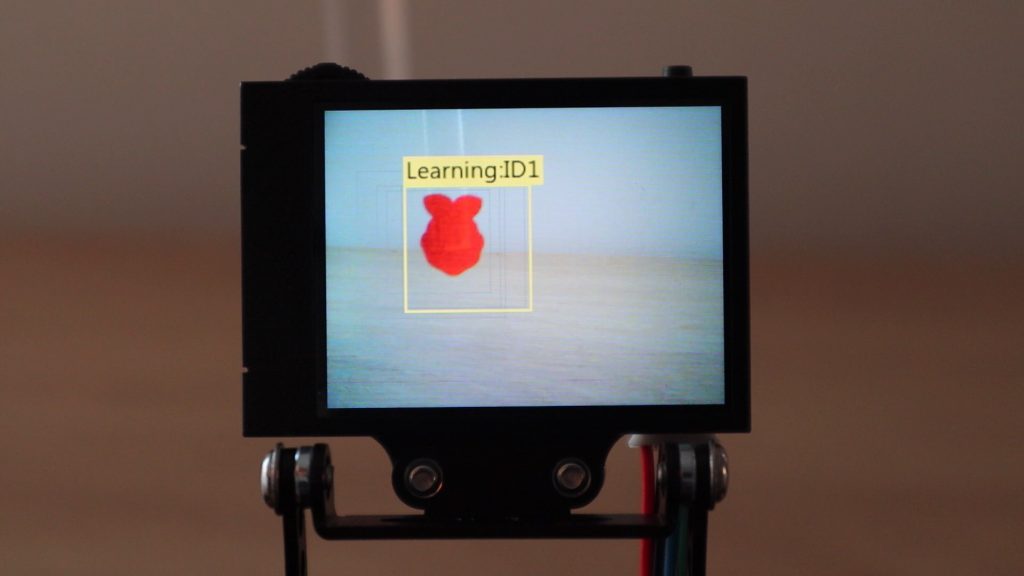
We use the selector to change over to Object Tracking mode. In this mode, the crosshair on the display is replaced by a yellow box. To start, you need to align the object you’re going to be tracking with this box and then press the learn button.
I’m going to try and use this Raspberry Pi logo cutout on a clear piece of acrylic as the object to track.
Once the object is learnt, it’ll receive an ID tag and it’ll then be followed around the display surrounded by the box. It also gets bigger or smaller if you move it closer and further away from the camera.
We’re going to use this box to control the car as well. When the box moves to the left or right of the display then we’ll move the car left or right and when it gets further away, the box gets smaller, and we’ll then move the car forward to follow the object.
I’ve adapted my old robot car code again, this time to follow the box around the screen.
//The DIY Life
//Michael Klements
//16/04/2021
//HuskyLens Object Tracking Robot

#include "HUSKYLENS.h"                            //Import the required libraries
#include "SoftwareSerial.h"
#include <AFMotor.h>

AF_DCMotor rightBack(1);                          //Create an object to control each motor
AF_DCMotor rightFront(2);
AF_DCMotor leftFront(3);
AF_DCMotor leftBack(4);

byte maxMotorSpeed = 50;                             //The normal motor speed
int motorOffset = 25;                             //Factor to account for one side being more powerful
int objectWidth = 50;
int turnGain = 12;
int offCentre = 20;
int distGain = 6;

int leftLimit = 160-offCentre;
int rightLimit = 160+offCentre;

int leftSp = 0;
int rightSp = 0;

bool isTurning = false;                           //Track when turning left and right
bool isTurningLeft = true;

HUSKYLENS huskylens;                              //Create a new Huskeylens object
int ID1 = 1;

void printResult(HUSKYLENSResult result);

void setup()
{
  Serial.begin(115200);                                       //Start serial communication
  Wire.begin();                                               //Connect to Huskylens
  while (!huskylens.begin(Wire))
  {
      Serial.println(F("Begin failed!"));
      Serial.println(F("1.Please recheck the \"Protocol Type\" in HUSKYLENS (General Settings>>Protol Type>>I2C)"));
      Serial.println(F("2.Please recheck the connection."));
      delay(100);
  }
  huskylens.writeAlgorithm(ALGORITHM_OBJECT_TRACKING);        //Switch the algorithm to object tracking.
  rightBack.setSpeed(0);                                      //Set the motors to the motor speed
  rightFront.setSpeed(0);
  leftFront.setSpeed(0);
  leftBack.setSpeed(0);
  moveForward();                                              //Set motors to forward direction
}

void loop()
{
  int32_t error;
  if (!huskylens.request())                                                 //If connection to Huskylens isn't available
    Serial.println(F("Fail to request objects from HUSKYLENS!"));
  else if(!huskylens.isLearned())                                           //If an object hasn't yet been learned
  {
    Serial.println(F("Object not learned!"));
    setMotorSpeed (0,0);
  }
  else if(!huskylens.available())                                           //If the learned object isn't visible anymore
  {
    Serial.println(F("Object disappeared!"));
    setMotorSpeed (0,0);
  }
  else                                                                      //If object is being tracked
  {
     HUSKYLENSResult result = huskylens.read();                             //Get the results of the object being tracked
     if(result.xCenter < leftLimit)
     {
        leftSp = -turnGain*(leftLimit-result.xCenter);
        rightSp = turnGain*(leftLimit-result.xCenter);
     }
     else if(result.xCenter > rightLimit)
     {
        leftSp = turnGain*(result.xCenter-rightLimit);
        rightSp = -turnGain*(result.xCenter-rightLimit);
     }
     if(result.width < objectWidth)
     {
        leftSp = leftSp+(distGain*(objectWidth-result.width));
        rightSp = rightSp+(distGain*(objectWidth-result.width));
     }
     if(leftSp > maxMotorSpeed)
        leftSp = maxMotorSpeed;
     else if(leftSp < 0)
        leftSp = 0;
     if(rightSp > maxMotorSpeed)
        rightSp = maxMotorSpeed;
     else if(rightSp < 0)
        rightSp = 0;
     setMotorSpeed (leftSp, rightSp);
     leftSp = 0;
     rightSp = 0;
     printResult(result);
  }
}

void moveForward()                                //Set all motors to run forward
{
  rightBack.run(FORWARD);
  rightFront.run(FORWARD);
  leftFront.run(FORWARD);
  leftBack.run(FORWARD);
}

void stopMove()                                   //Set all motors to stop
{
  rightBack.run(RELEASE);
  rightFront.run(RELEASE);
  leftFront.run(RELEASE);
  leftBack.run(RELEASE);
}

void setMotorSpeed (int leftTempSp, int rightTempSp)
{
  rightBack.setSpeed(rightTempSp);                              //Set the motors to the motor speed
  rightFront.setSpeed(rightTempSp);
  leftFront.setSpeed(leftTempSp+motorOffset);
  leftBack.setSpeed(leftTempSp+motorOffset);
}

void printResult(HUSKYLENSResult result)                        //Display the results on the serial monitor
{
    if (result.command == COMMAND_RETURN_BLOCK)
    {
        Serial.println(String()+F("Block:xCenter=")+result.xCenter+F(",yCenter=")+result.yCenter+F(",width=")+result.width+F(",height=")+result.height+F(",ID=")+result.ID);
    }
    else if (result.command == COMMAND_RETURN_ARROW)
    {
        Serial.println(String()+F("Arrow:xOrigin=")+result.xOrigin+F(",yOrigin=")+result.yOrigin+F(",xTarget=")+result.xTarget+F(",yTarget=")+result.yTarget+F(",ID=")+result.ID);
    }
    else
    {
        Serial.println("Object unknown!");
    }
}I uploaded the code to the robot and then tried the tracking out. This example took a bit more time to set up and get to a point where it was working reasonably reliably. Most of the time was spent adjusting the gains on the turning and distance tracking as it seemed to either not respond at all or respond too aggressively.
I eventually got it working reasonably well. The robot followed the Raspberry Pi logo around, moving forward when it was moved away and turning left and right to bring it back into the centre of the display.
You can watch the object tracking in the video at the beginning of this project as well.
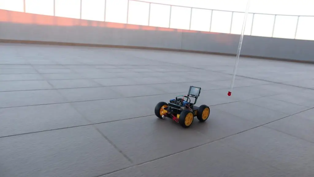
I probably need to spend a bit more time adjusting the gains, but you get a good idea of how the object tracking works.
I’d also like to try the object tracking mode on a two axis servo mount, as I think the results would be a bit more reliable and consistent than with the car.
Let me know what you think of the Huskylens and my robot car in the comments section below.
Hi Michael, great project. I had done some test with Huskylens and have build your project and have actually also used Tag recognition. Works great as well and Tags are often more instantly recognized than objects, depending on the objects shape “learning ID:1….”
Hi Hans. That’s great, thanks for sharing!
Hi,
I have tried the line following code, with the same setup, but it does not follow the line. Could you advise?
There could be a number of reasons why yours isn’t working. You might need to adjust your motor gains, you might need to adjust the PID gains, your Huskylens might not be picking up the line correctly. Although the setup is similar, small differences might result in the car behaving differently.
I followed the line tracking code you gave me and it worked well. By the way, I have a question. It’s uncomfortable because the motor keeps moving when the line is not recognized. What do I have to do to stop when I’m not doing line training?
i have a same problem too please help me bro
has the huskylens arduino library expired? it is not considered a valid library by the ide
Not that I know of. What do you mean by it is not considered valid? A library can’t expire as such, it just becomes unsupported by the developer. You can still import an old library into the IDE, it doesn’t check that it is current.
Where is PIDLoop ?? Please answer thank you!
Same, I cannot find the PIDLoop.h library
l can’t find PIDLoop.h Library too Help me plz
Is there any way to get access to the raw camera feed as well? Wanting to output the video to Rasp Pi so I can use it in place of a different camera I have for remote viewing.
Thanks!
Hey Michael, where can I get the “Huskylens.h” and “AFMotor.h” files?
You can install them through the library manager.
Bon dia Michael, Como voce mesmo falou se colocar dois servos motorees para movimentar o Huskylens.h como se fosse o pescoço movimentando a cabeça acho que ficaeria mais prociso o rastreamento e mais statico pra um Robô. Voce poderia acrescentar essa função nesse código?
Hey Michael, how can I switch * huskylens.writeAlgorithm(ALGORITHM_OBJECT_TRACKING);* to*huskylens.writeAlgorithm(ALGORITHM_LINE_TRACKING);* by use cmd
hi sorry if this is a stupid question but i am new to programing is it at all possible to add the object tracking to a device that is currently controlled by a remote so that you can switch between manual and automated control? any help or advice on where to look would be very much appreciated.
You would need to add a microcontroller to the device to control the switching over etc, but you could probably make it work.
Hello Michael, thank you very much for your project.
I recreated the second part “Object Tracking”. Unfortunately, I don’t have such ideal conditions as the white floor where you have. In my workspace there is a lot of background next to the object on the HuskyLens display. Unfortunately, this is where the limits of the Huskies become apparent to me. Even a small background throws the HuskyLens off course and the object is constantly lost. This means that smooth tracking cannot be achieved. It’s a shame actually. I would have expected more from this module.
Have you already had these experiences?
Is there also a possibility that the car drives backwards when you approach the car with the object and thus the frame becomes larger?
Many greetings ULLI
Hello Michael, thank you very much for your project.
I recreated the second part “Object Tracking”. Unfortunately, I don’t have such ideal conditions as the white floor where you have. In my workspace there is a lot of background next to the object on the HuskyLens display. Unfortunately, this is where the limits of the Huskies become apparent to me. Even a small background throws the HuskyLens off course and the object is constantly lost. This means that smooth tracking cannot be achieved. It’s a shame actually. I would have expected more from this module.
Have you already had these experiences?
Many greetings ULLI
Is there also a possibility that the car drives backwards when you approach the car with the object and thus the frame becomes larger?
Many greetings ULLI
Hi Michael,
I love this project and I am about to order another housing from you. I am not a programmer and I am getting this error:
Traceback (most recent call last):
File “/home/pi/Adafruit_Python_SSD1306/stats.py”, line 123, in
aReceiveBuf.append(bus.read_byte_data(DEVICE_ADDR, i))
File “/home/pi/.local/lib/python3.9/site-packages/smbus2/smbus2.py”, line 433, in read_byte_data
ioctl(self.fd, I2C_SMBUS, msg)
OSError: [Errno 121] Remote I/O error
I am using the file from danb35/raspi-ups-stats.
Any assistance would be appreciated.
Many Thanks
Pls anyone… where can i find PIDLoop.h library? it shows compilation error due to the fact that no such directory found. 🙁
me too please help
Thankyou for your project.
What is arduino coding instruction led turn and off?
#include
#include “HUSKYLENS.h”
#include
// Define SoftwareSerial pins for HuskyLens
#define HUSKY_TX 2
#define HUSKY_RX 3
SoftwareSerial huskySerial(HUSKY_TX, HUSKY_RX); // RX, TX
HUSKYLENS huskylens;
// Set the pin out for Motor 1
int RPWM_M1 = 5; // RPWM for Motor 1
int LPWM_M1 = 6; // LPWM for Motor 1
int L_EN_M1 = 7; // L_EN for Motor 1
int R_EN_M1 = 8; // R_EN for Motor 1
// Set the pin out for Motor 2
int RPWM_M2 = 9; // RPWM for Motor 2
int LPWM_M2 = 10; // LPWM for Motor 2
int L_EN_M2 = 11; // L_EN for Motor 2
int R_EN_M2 = 12; // R_EN for Motor 2
// Define pins for the ultrasonic sensor
#define TRIGGER_PIN 4
#define ECHO_PIN 13
// Define maximum distance (in cm) for the ultrasonic sensor
#define MAX_DISTANCE 200
NewPing sonar(TRIGGER_PIN, ECHO_PIN, MAX_DISTANCE);
const int desiredDistance = 30; // Desired distance from the object in cm
int lastLeftSpeed = 0;
int lastRightSpeed = 0;
void setup() {
// Initialize all pins to output
pinMode(RPWM_M1, OUTPUT);
pinMode(LPWM_M1, OUTPUT);
pinMode(L_EN_M1, OUTPUT);
pinMode(R_EN_M1, OUTPUT);
pinMode(RPWM_M2, OUTPUT);
pinMode(LPWM_M2, OUTPUT);
pinMode(L_EN_M2, OUTPUT);
pinMode(R_EN_M2, OUTPUT);
pinMode(TRIGGER_PIN, OUTPUT);
pinMode(ECHO_PIN, INPUT);
delay(1000); // Wait for a second
Serial.begin(9600); // Initialize hardware serial for debugging
huskySerial.begin(9600); // Initialize SoftwareSerial for HuskyLens
// Enable “Right” and “Left” movement on the H-Bridge for both motors
digitalWrite(R_EN_M1, HIGH);
digitalWrite(L_EN_M1, HIGH);
digitalWrite(R_EN_M2, HIGH);
digitalWrite(L_EN_M2, HIGH);
while (!huskylens.begin(huskySerial)) {
delay(100);
}
}
void loop() {
delay(50); // Short delay to avoid overloading the serial communication
// Get distance from ultrasonic sensor
unsigned int distance = sonar.ping_cm();
// Ensure distance measurement is valid
if (distance == 0 || distance > MAX_DISTANCE) {
distance = MAX_DISTANCE;
}
if (!huskylens.request()) {
stopMoving();
} else if (!huskylens.isLearned()) {
stopMoving();
} else if (!huskylens.available()) {
stopMoving();
} else {
while (huskylens.available()) {
HUSKYLENSResult result = huskylens.read();
// Move the motors based on the object position and distance
if (result.command == COMMAND_RETURN_BLOCK) {
int center = 160; // Assuming a 320×240 screen resolution
int error = result.xCenter – center;
// Adjust speed based on the error to smoothly follow the object
int turnSpeed = map(abs(error), 0, center, 0, 128);
if (turnSpeed > 128) turnSpeed = 128; // Ensure max speed does not exceed 128
if (distance < desiredDistance – 5) {
// Object is too close, move backward immediately
moveBackward();
} else if (error 10) {
// Object is right of center, turn right to center it
moveRight(turnSpeed);
} else {
// Object is in the center and at the correct distance
if (distance > desiredDistance + 5) {
// Object is too far, move forward
moveForward();
} else {
// Object is at the desired distance, stop
stopMoving();
}
}
}
}
}
}
void moveForward() {
setMotorSpeed(128, 128);
}
void moveBackward() {
setMotorSpeed(-128, -128);
}
void moveLeft(int speed) {
setMotorSpeed(-speed, speed);
}
void moveRight(int speed) {
setMotorSpeed(speed, -speed);
}
void stopMoving() {
setMotorSpeed(0, 0);
}
void setMotorSpeed(int leftSpeed, int rightSpeed) {
// Check if the new speeds are different from the last speeds
if (leftSpeed != lastLeftSpeed || rightSpeed != lastRightSpeed) {
if (leftSpeed >= 0) {
analogWrite(RPWM_M1, leftSpeed); // Left motor forward
analogWrite(LPWM_M1, 0);
} else {
analogWrite(RPWM_M1, 0);
analogWrite(LPWM_M1, -leftSpeed); // Left motor backward
}
if (rightSpeed >= 0) {
analogWrite(RPWM_M2, rightSpeed); // Right motor forward
analogWrite(LPWM_M2, 0);
} else {
analogWrite(RPWM_M2, 0);
analogWrite(LPWM_M2, -rightSpeed); // Right motor backward
}
// Save the last speeds
lastLeftSpeed = leftSpeed;
lastRightSpeed = rightSpeed;
}
}
Hi, this a code ChatGTP made for me. Its with two BTS7960 controllers and a ultrasonic sensor to go backward if the object is to close. Its works so heavy motors can be used.