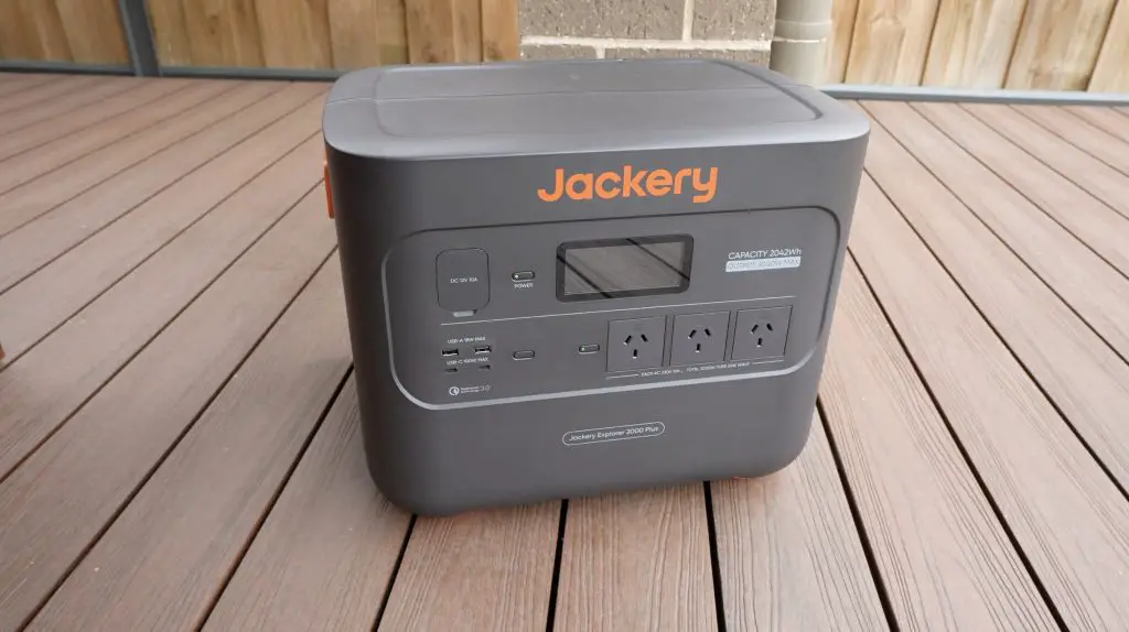
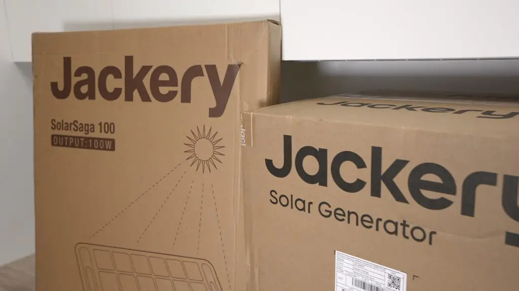
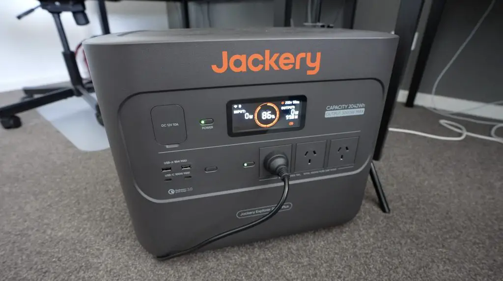
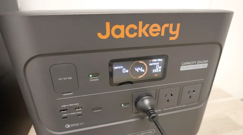
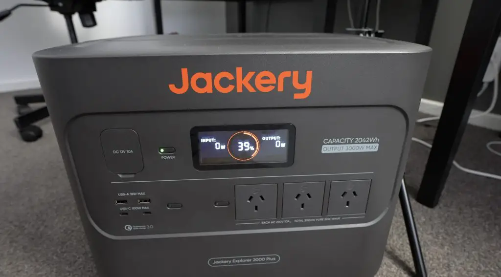
Jackery recently asked if I’d like to try out their new Solar Generator 2000 Plus portable power station. It’s got some great features like 3000W continuous output and a 2042Wh capacity. I’ve done a full review on it if you’d like to check that out for some more of the technical specs and my thoughts on it – full review. The Solar Generator 2000 Plus is a kit that is made up of the Explorer 2000 Plus portable power station and a 100W SolarSaga solar panel.
The review got me thinking, could I design, 3D print, laser cut and assemble a Mini ITX computer using a single charge of the Explorer 2000 Plus? 2042Wh is a lot for a portable power station, but would that be enough to last when using my computer for a couple of hours worth of design time, possibly a full day of 3D printing and then to power the tools and computer through assembly and setup?
Here’s my video of the project, read on for the write-up;
What You Need To Build Your Own Mini ITX Computer
- AMD Ryzen 5 5500 – Buy Here
- ASRock B550M-ITX – Buy Here
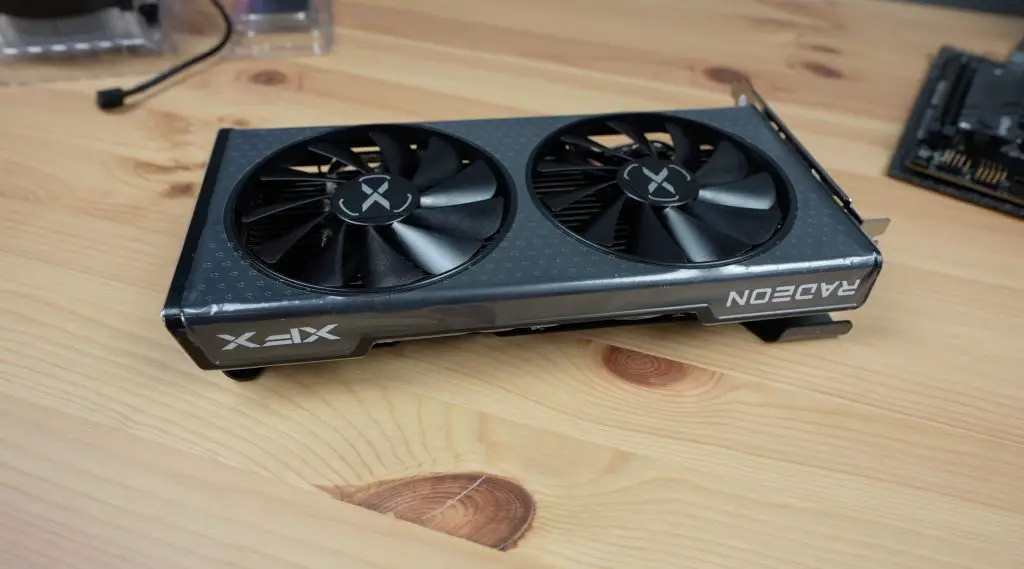
- XFX SWFT Radeon RX 6600 – Buy Here
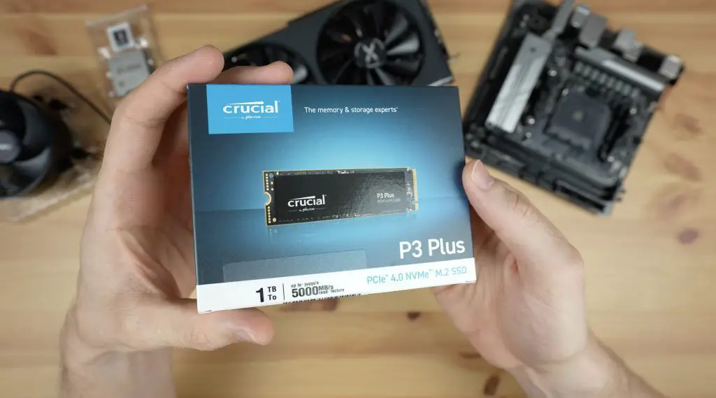
- Crucial 1TB P3 Plus – Buy Here
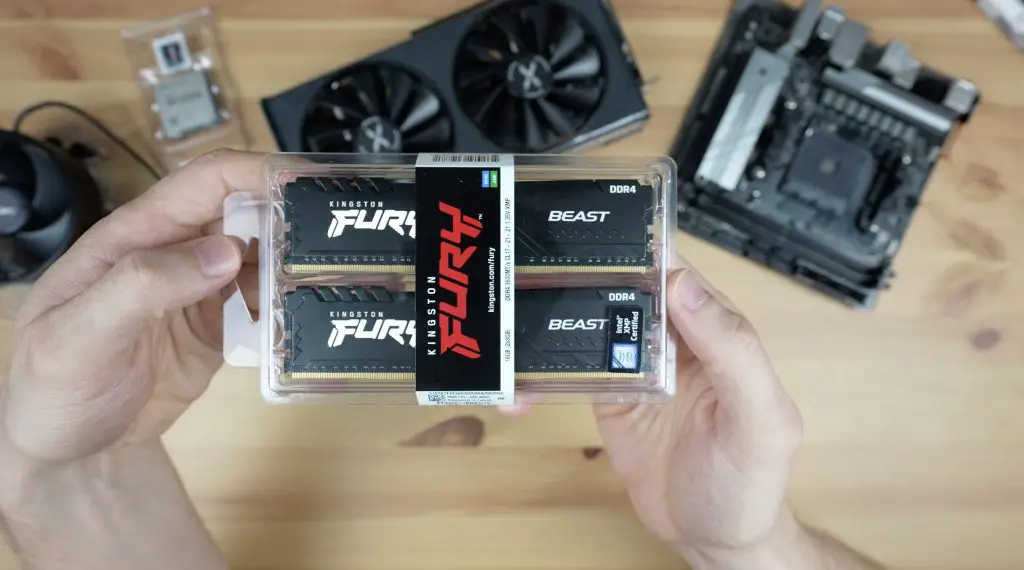
- Kingston Fury Beast Black 16GB – Buy Here
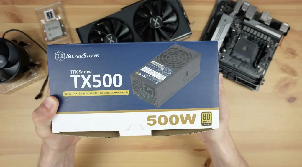
- Silverstone 500W TFX Power Supply – Buy Here
- PCI-E 4.0 Riser Cable – Buy Here
- M3x8mm Button Head Screw Kit – Buy Here
- Power Button – Buy Here
- M3 Brass Inserts – Buy Here
Tool & Equipment Used:
- Bambulab P1S – Buy Here
- Gweike Cloud CO2 Laser Cutter – Buy Here
- USB C Electric Screwdriver – Buy Here
- Hakko Soldering Iron – Buy Here
- Hakko Brass Insert Tips – Buy Here
Setting The Ground Rules
Before starting with the design, I need to set some ground rules for the project.
I’m going to be limited to a single charge of the Explorer 2000 Plus. I’ll charge it up at the beginning of the project and I can only use power from it to power any computer equipment, printers, tools or chargers that I need to get the mini ITX computer designed, printed, assembled and booted up.
I also can’t use previously stored power in battery-powered devices. If I have to use a battery-powered device like my laptop then I’ll drain it completely before starting and I’ll need to use the Explorer 2000 Plus to charge it as well.
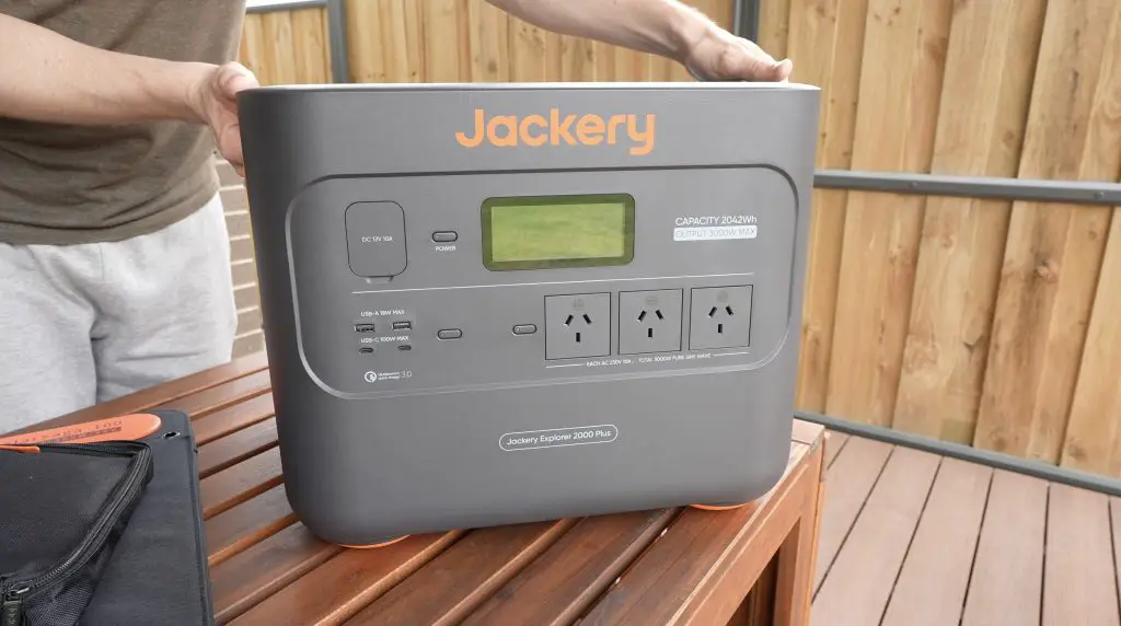
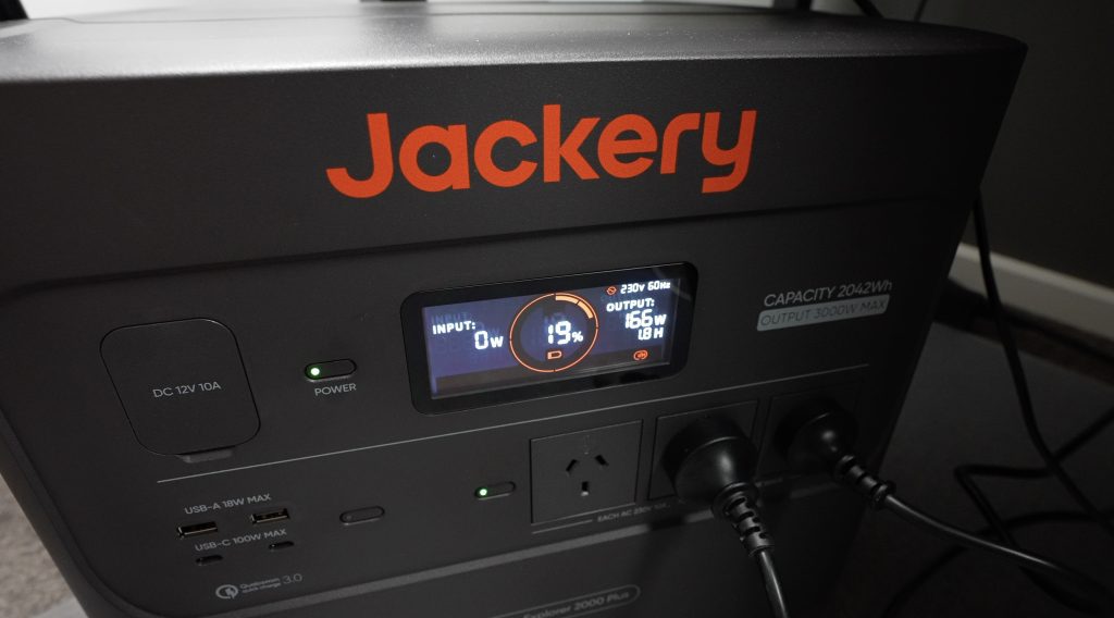
Charging The Jackery Solar Generator 2000 Plus
To start, let’s get the power station charged up.

There are three ways to charge it, the fastest is going to be plugging it into mains power, which will fully charge it from empty in just 2 hours.
The second way is through solar power. This varies by how many panels you connect to it and how strong the sun is, but with 6 of their 100W panels, you can get it fully charged in just 5.5 hours.
The third is through a car’s 12V DC socket. This is the slowest option and will take around 20-22 hours to get it fully charged.
We’re heading into summer here and we have nice bright long days, so I’m going to use the solar option.
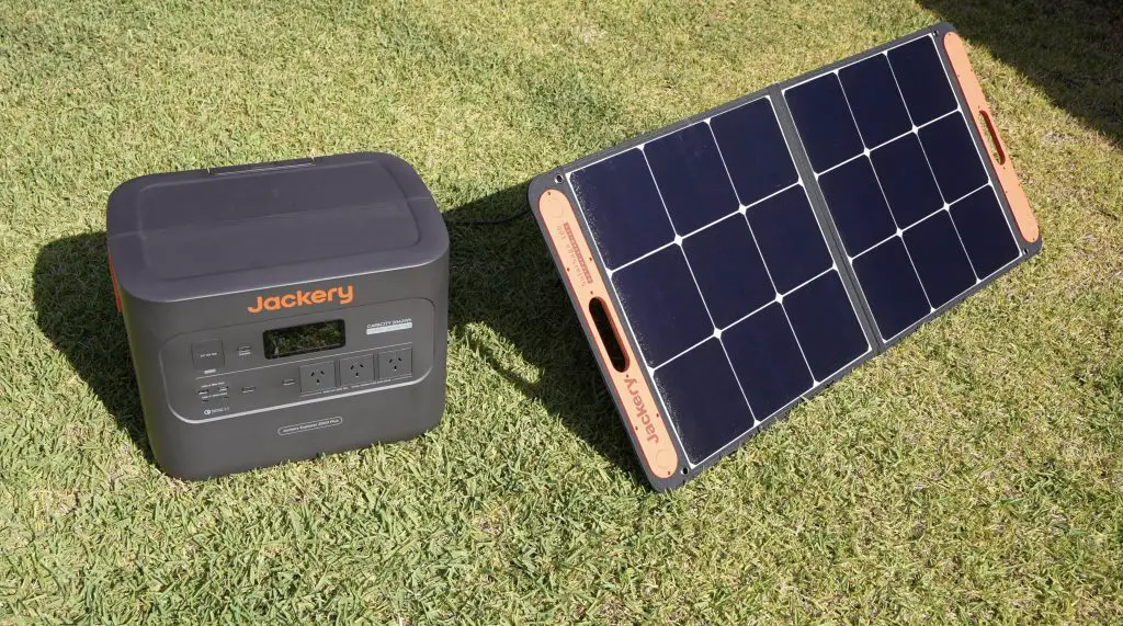
The SolarSaga 100 panel is a 100W foldable design that is IP65 waterproof and includes integrated USB ports for charging directly from the panel.
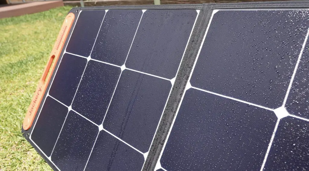
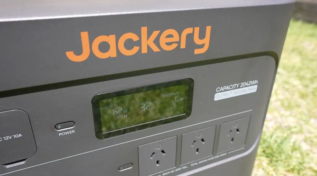
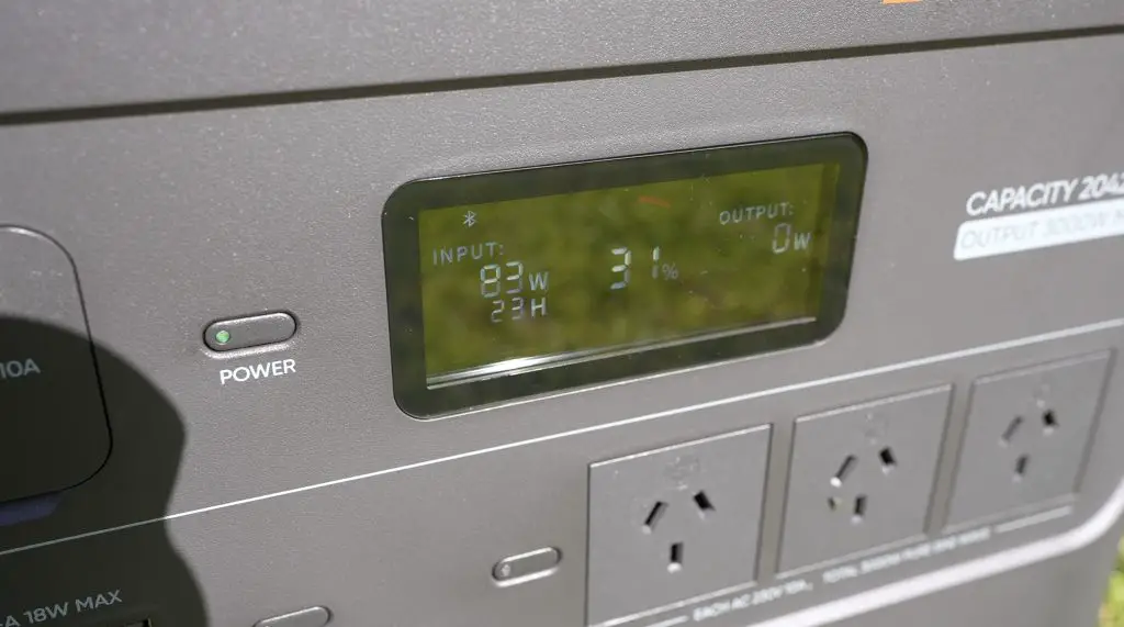
I’ve got the panel hooked up to the Explorer 2000 Plus and it’s set up outside in full sun to charge. In the morning sun it’s outputting around 60-70W, by midday it was outputting around 83W. Even at 83W, it’s still going to be a while but that’s an improvement on the morning results and it’s essentially free energy.
After two days of charging, it’s now full and ready to start the challenge.

Mini ITX PC Components Chosen For The Build
Next, let’s take a look at the components that I’ve chosen for the PC build.
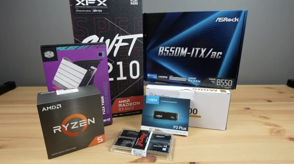
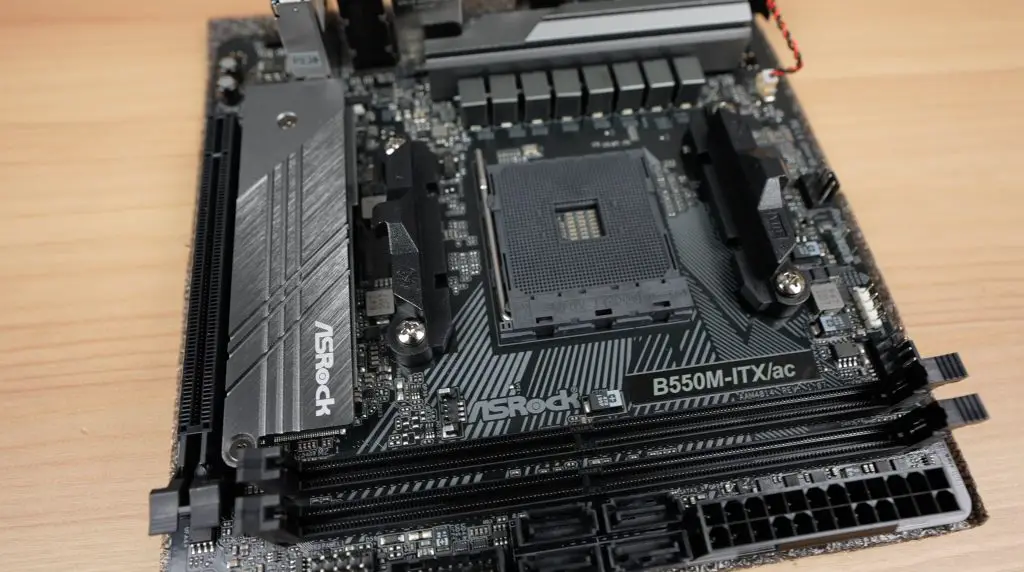
I want this to be a compact but still reasonably powerful computer so I’ve gone with this ASRock B550M-ITX Mini ITX form factor motherboard.
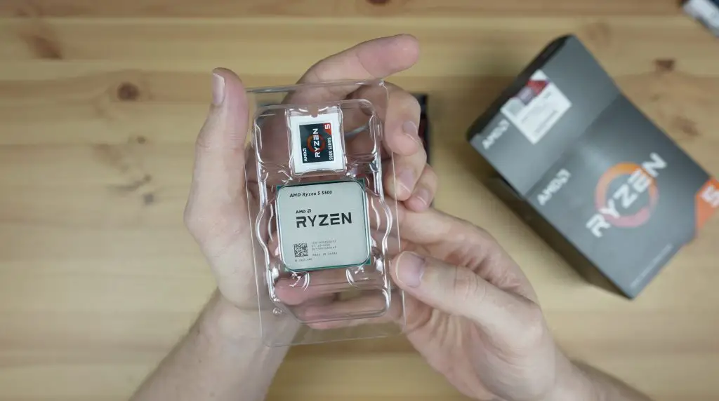
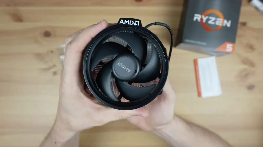
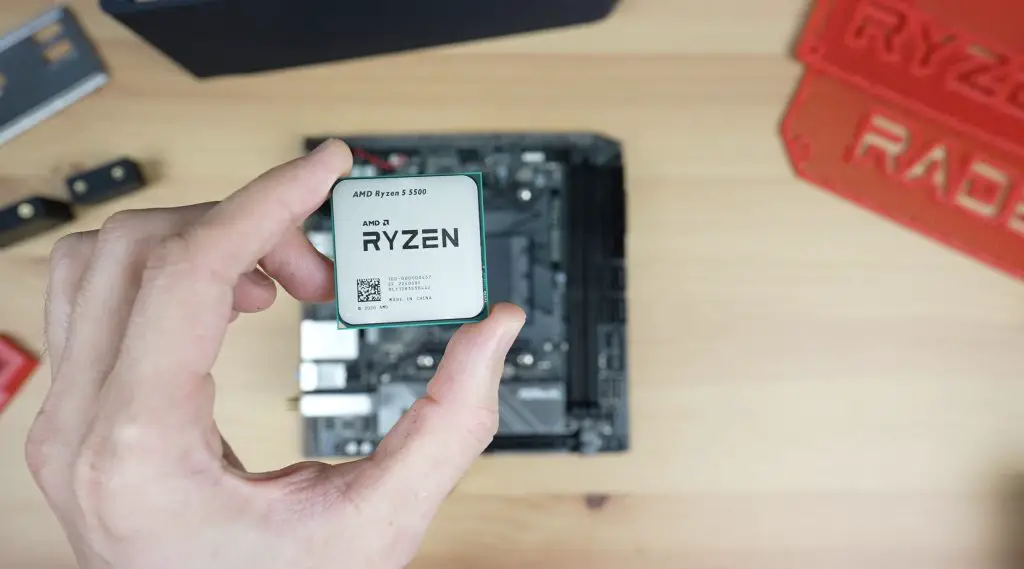
For the processor, the Ryzen 5 5500 is a good balance between value for money and performance. It also doesn’t require a large amount of power so we can get away with a compact power supply. It also comes with a basic cooler to keep the cost down.
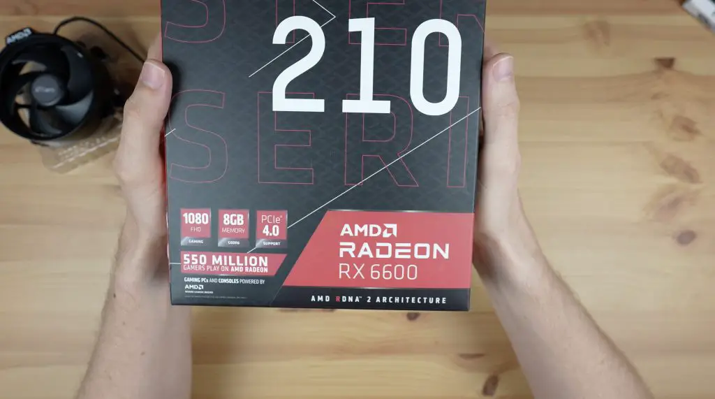
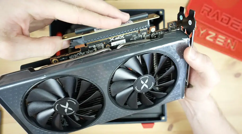
For graphics, since the Ryzen 5 5500 doesn’t have integrated graphics, I’ve got a dedicated Radeon RX 6600 GPU. This card also strikes a good balance between value for money and performance.
Lastly, I’ve got two 8GB sticks of DDR4 RAM and a 1TB NVME SSD. To power the computer I’ve got a 500W Silverstone TFX power supply.
This setup should be perfect to run most modern games at 1080P and reasonably high settings.
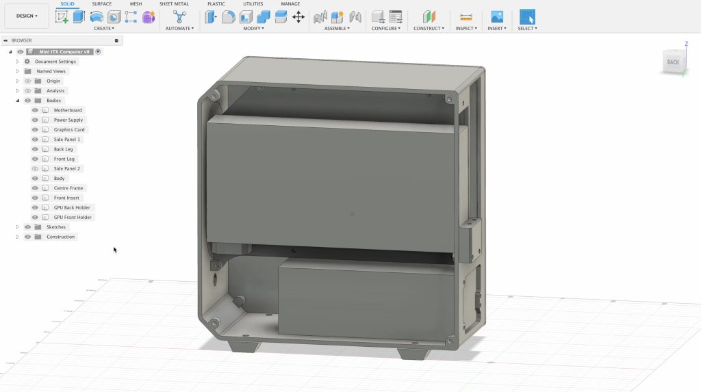
Designing The Mini ITX Computer Case
In terms of layout, I’m going to go with the power supply beneath the motherboard as it’s got a fan on the top and I’ll mount the GPU vertically on the back of the motherboard to save space. The GPU is quite big so is going to be the limiting factor in how compact we can get the case.
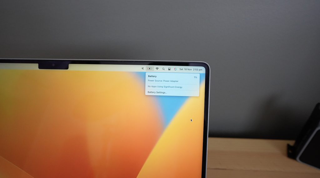
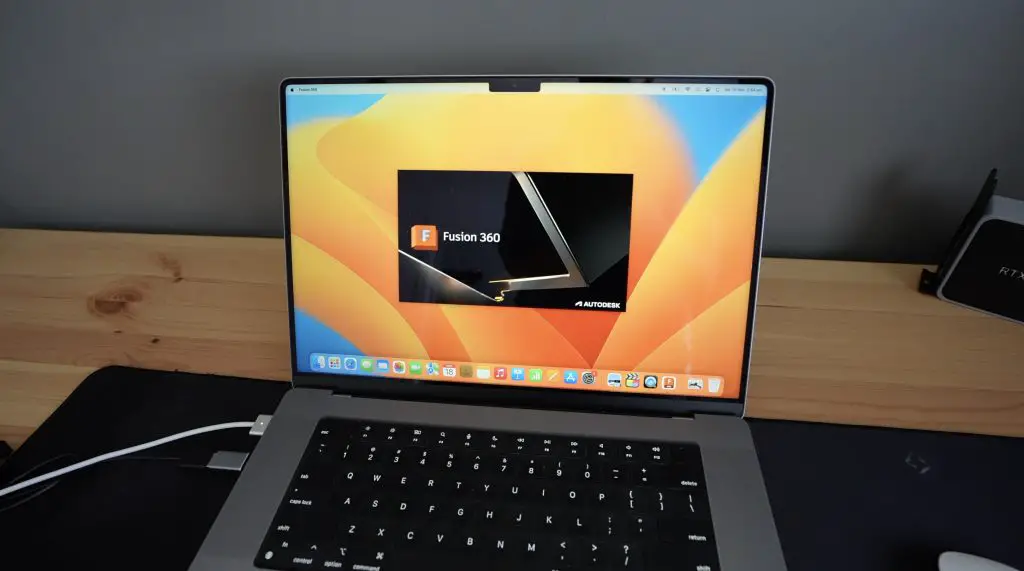
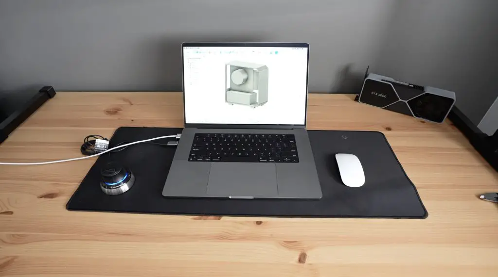
Let’s get started with the CAD design and for that, I’m going to use my Macbook which is now dead. So let’s plug it into a USB C port on the Explorer 2000 Plus and use that to charge and power it. My Macbook uses around 90W when charging up from dead but this should settle to under 10W once charged. Then we can open up Fusion360 to do the design.
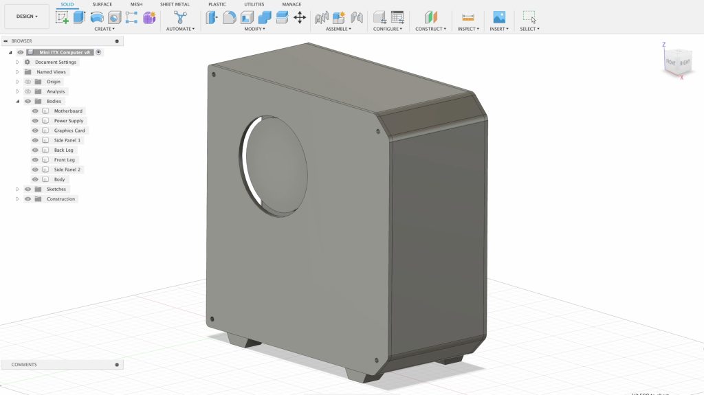
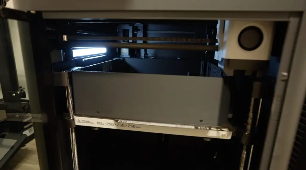
I’m going to go with an almost square design that’ll just fit onto my 3D printer’s 256 x 256mm print bed. I drew inspiration from my Raspberry Pi mini desktop case design that I did a couple of years ago.
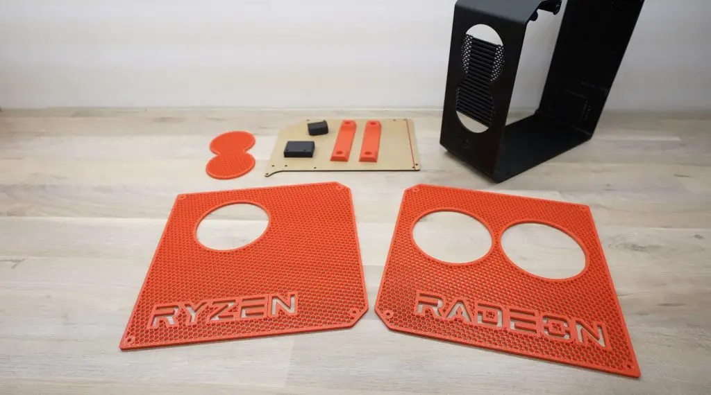
The main body of the mini ITX case will be a single part for rigidity. I’ll then laser-cut an acrylic panel for the middle which will be used to mount the motherboard and GPU. The side panels will each be removable with cutouts for the fans. I’m going to pattern the side panels with a hexagon mesh but I’ll do this with an infill trick in the slicer rather than try to do it in Fusion360. I also want to add some text cutouts to the side panels which I think will look pretty cool once the hexagon mesh is in place.
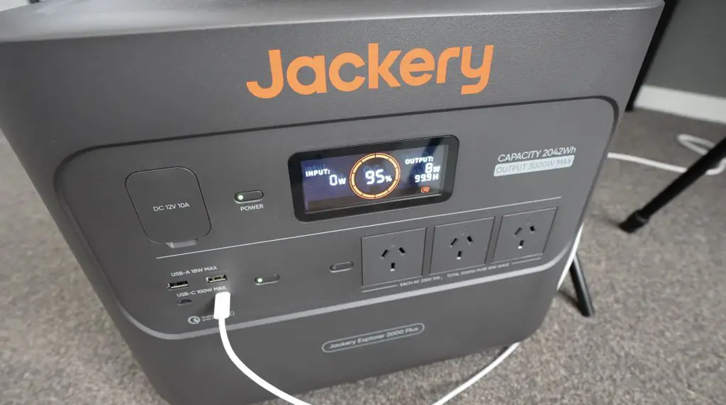
Halfway through the design I’ve used about 5% of the capacity, which is a bit less than I was expecting.
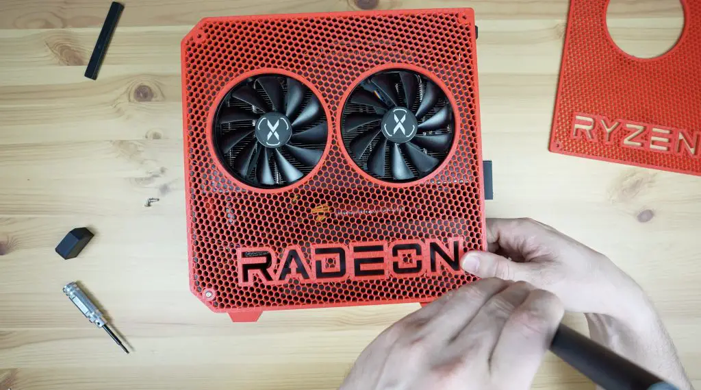
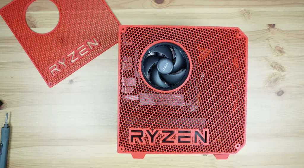
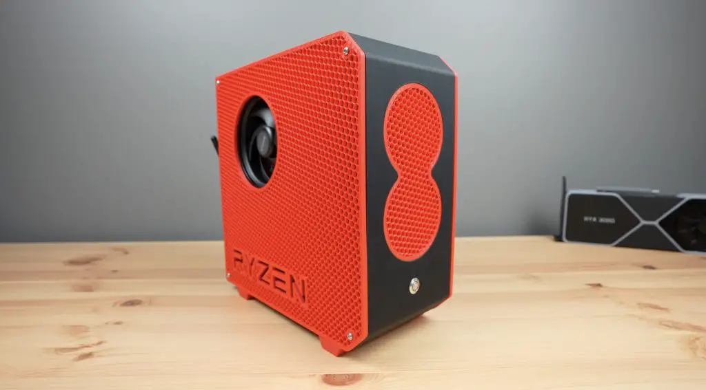
To make the front panel more appealing, I’ve added an insert that will have the same hexagon mesh pattern as the sides and there’s a cutout for the power button as well.
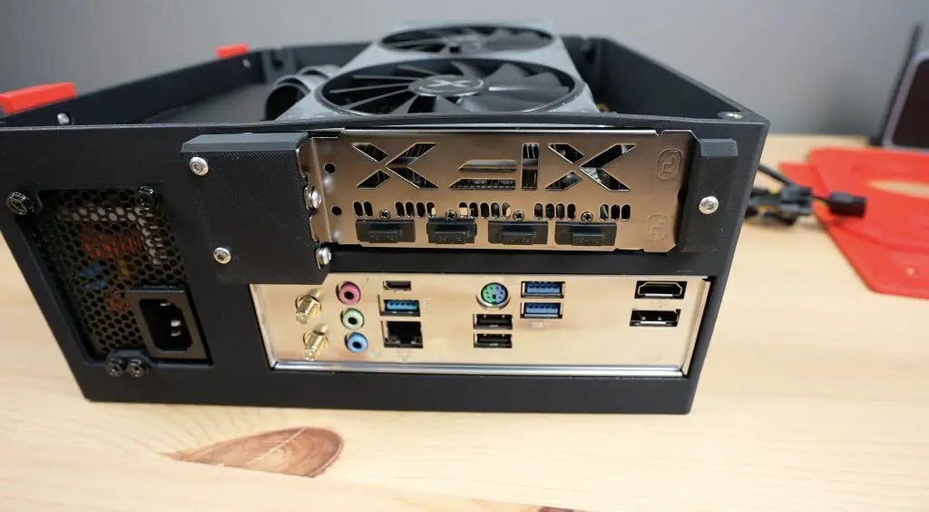
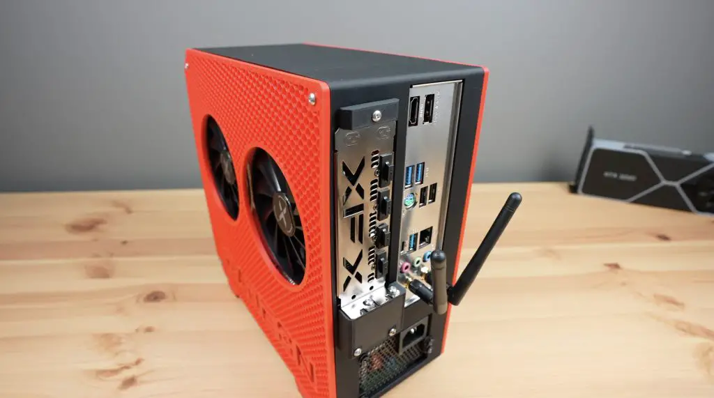
The back has cutouts for the power supply, motherboard IO shield and the GPU. The GPU mounting arrangement is a little bit unconventional as the case already takes up the whole print bed, so there is a small bracket that will need to be screwed onto the back of the case during assembly. I’ve also added some legs that screw onto the underside of the case.
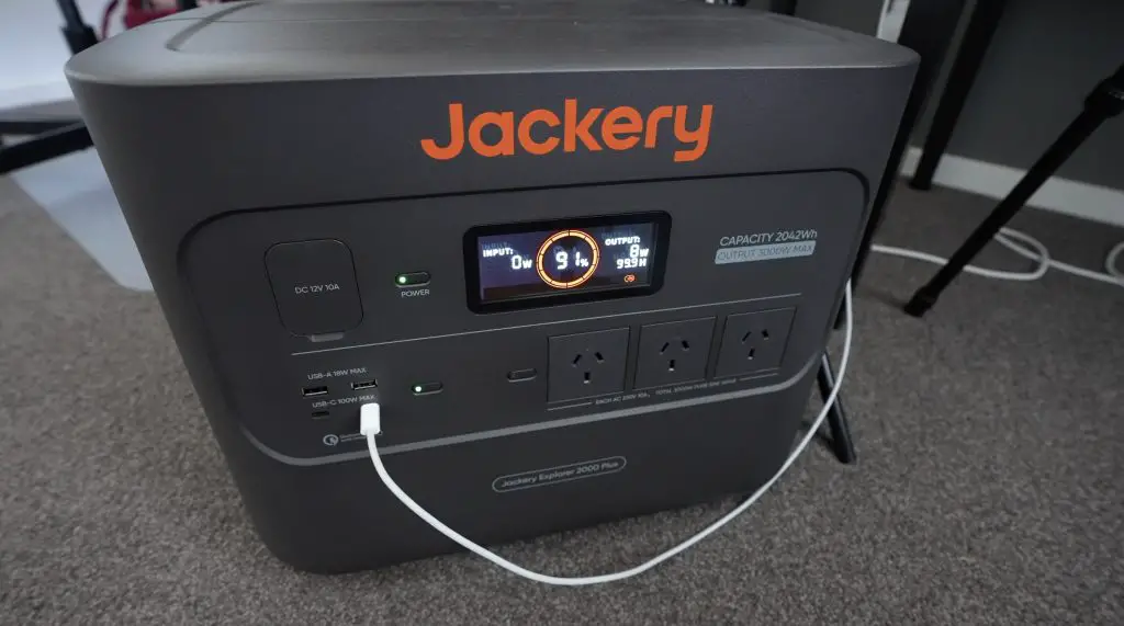
And that’s the mini ITX computer design complete. We’ve used 9% of the total charge, which is about 184Wh. That leaves quite a lot for printing and laser cutting but as with most projects, there is a strong possibility that I’ll need to come back and make tweaks to the model. I may even have to reprint parts of it at a later stage.
Slicing The Mini ITX Case For 3D Printing
With the design done, we need to export the model files for the components and then open them up in the slicer software. I’m using Bambu slicer and I’m going to use black PLA for the body of the case and red PLA for the sides, legs and front accent.
As I mentioned before, the case and side panels only just fit onto my print bed. On the Bambulab P1S, we need to make some modifications to the G-code and use a 3D printed adaptor to block off the cutting arm to be able to use the full bed.
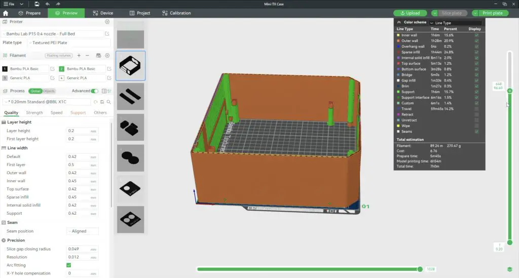
With all of the slicing done, we’ve now got 86% of the capacity available for printing and laser cutting, so let’s get started.
Making Up The Case Components
My P1S 3D printer uses a lot of power to warm up – just under 1000W. This will drop down to about 150 to 200W once warm and will remain at this level for the duration of the print.
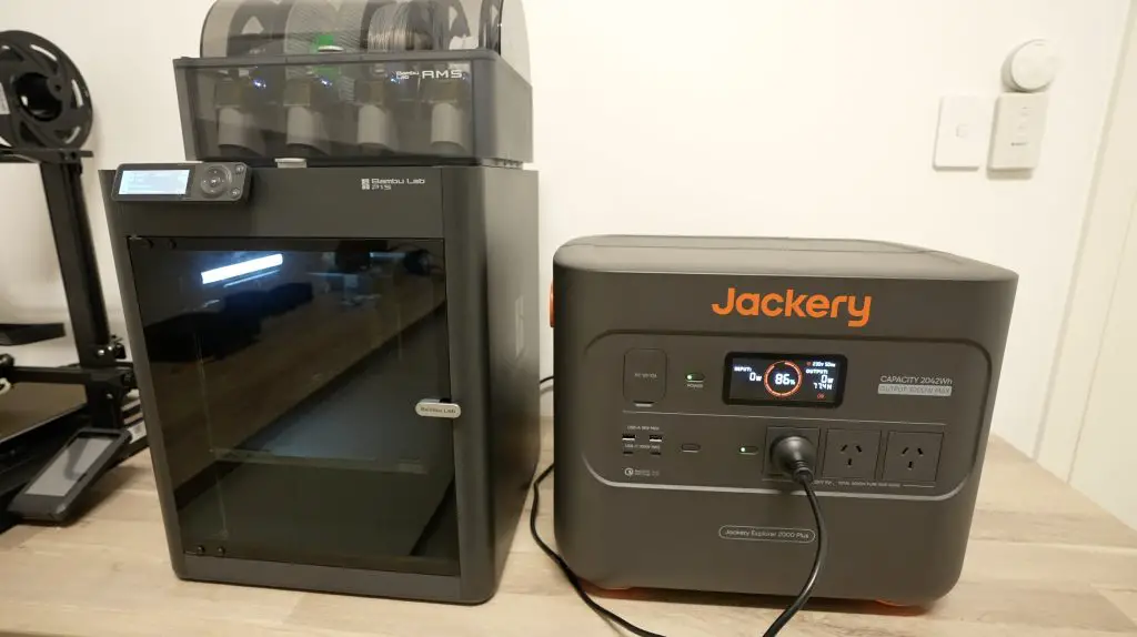
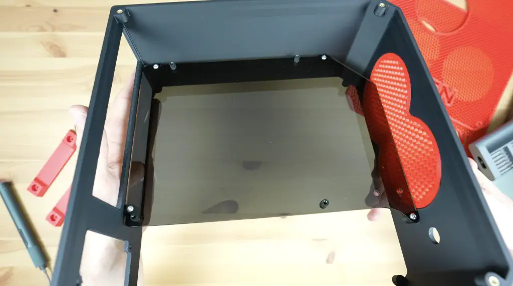
While the printer is running, I’m going to use the second AC output on the Explorer 2000 to power my laser cutter. We’ll use this to cut out the acrylic internal panel to mount the motherboard and GPU onto. I’m cutting this panel from a piece of 3mm grey tinted acrylic. I’ve included a 3D printable version in the design files if you don’t have a laser cutter but acrylic works well as a backing plate because it’s quite rigid.

The laser uses about 500W, which is added to the 150 to 200W that the 3D printer is already using. The laser is only running for a very short period so it won’t make much difference to the remaining capacity.
With the panel cut, we can move back to finishing off the 3D printing.
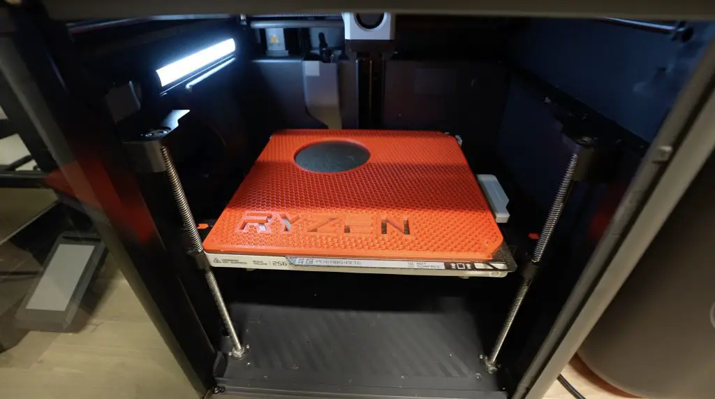
After a full day of 3D printing, all of the components are printed out. We’re now down to just 44% capacity. That’s quite a lot left to get through for what we still need to do, but that’s if we don’t have to re-print anything. I hope the parts all fit together properly and that the PC components fit into the case!
To complete the case components, we need to add a couple of M3 brass inserts into the main body of the case. To melt these into place I’m using a soldering iron with a brass insert tip and this too is running off the Explorer 2000.
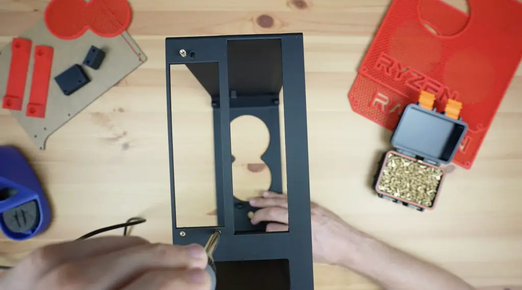
We also need to add two to each of these graphics card support brackets.
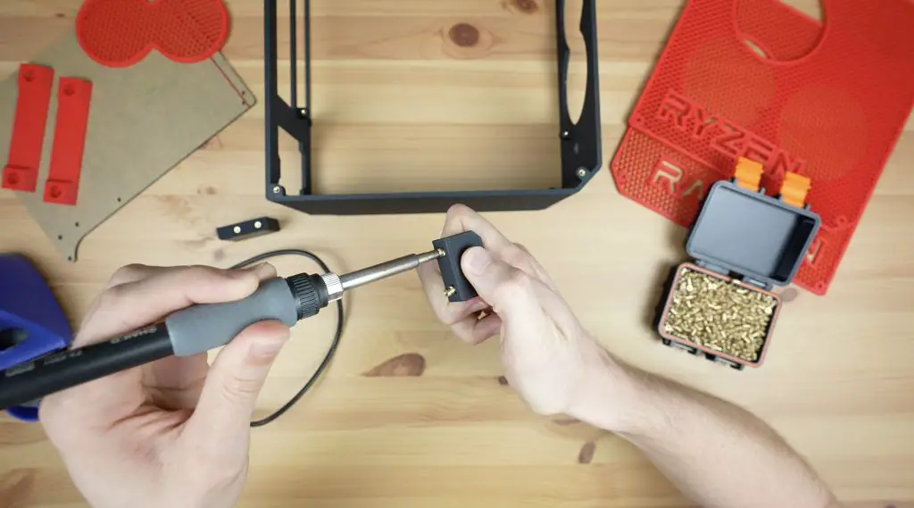
We need four on each side to mount the side panels onto, four to hold the acrylic panel in the middle and three to hold the graphics card at the back.
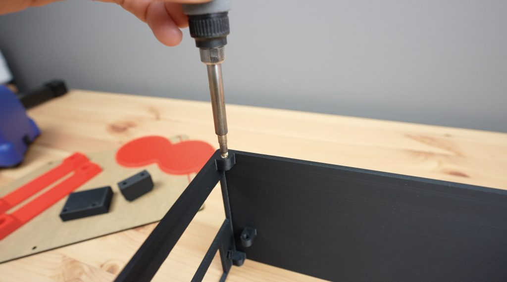
Assembling The Mini ITX Computer
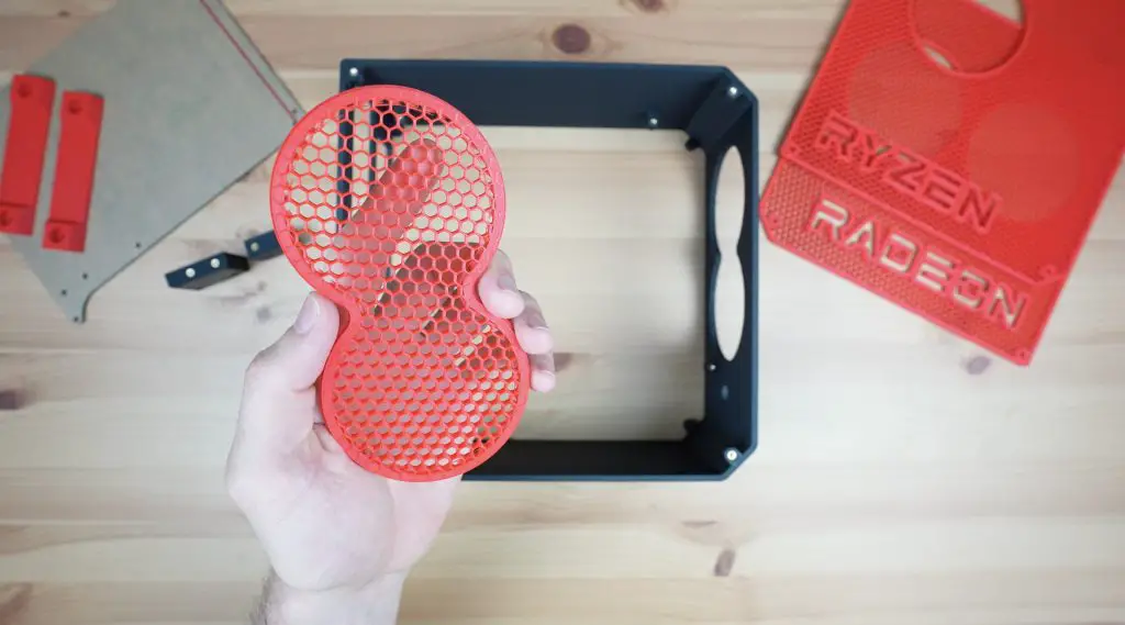
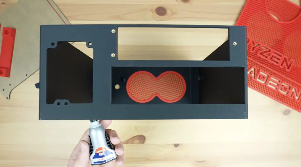
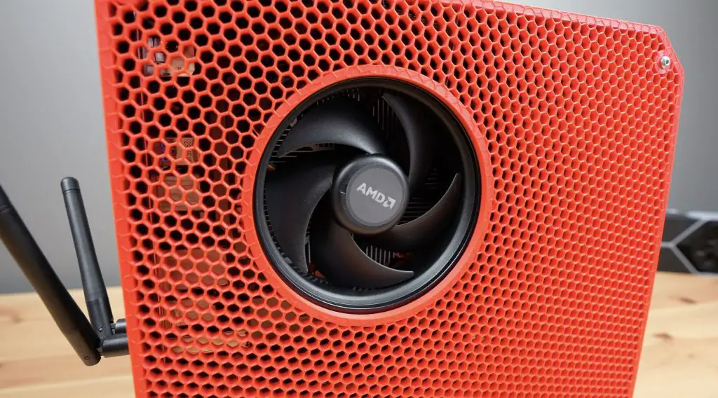
The front grill is press-fitted into place and we can add a couple of drops of superglue to secure it. I didn’t want to put any screws through it as it doesn’t need to be removable.
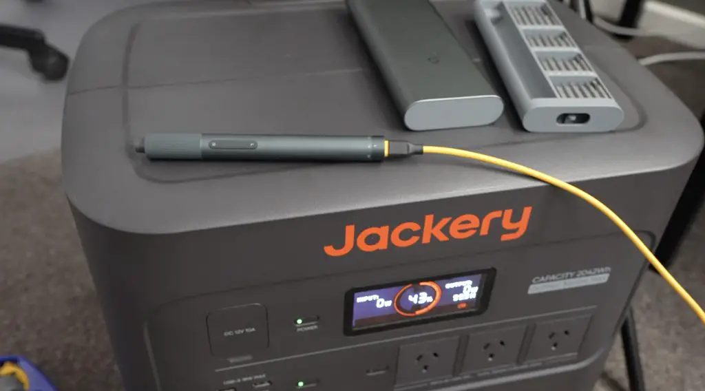
In keeping with the rules, I charged my USB C screwdriver on the power station, so that’s ready to go.
I’m going to add some M3x6mm nylon standoffs to the acrylic centre panel before I install it to mount the motherboard onto. You could use brass standoffs as an alternative, but I like nylon’s black appearance and we won’t have to worry about shorting components if they come loose.
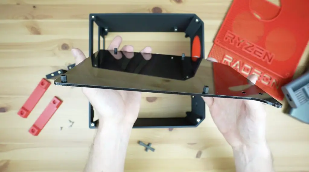
We can then install the acrylic centre panel with some M3x8mm button head screws.
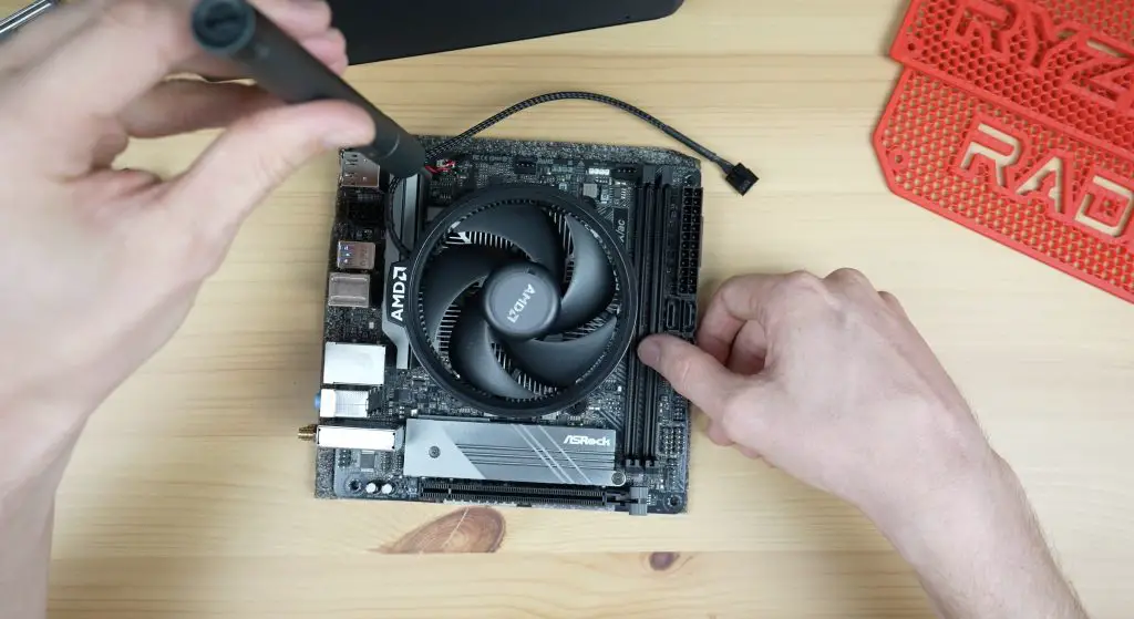
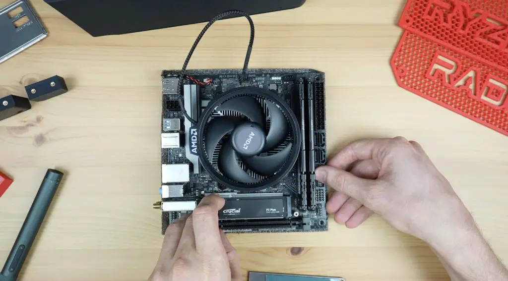
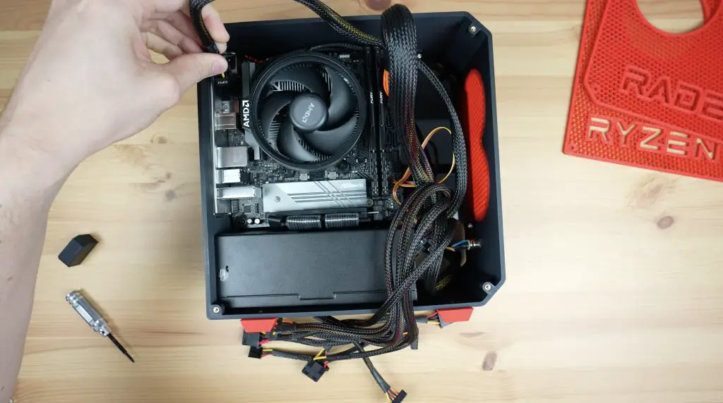
Next, we can assemble and add our motherboard.
First, let’s install the processor and heatsink. The heatsink comes with thermal compound pre-applied, so we don’t need to add any onto the CPU.
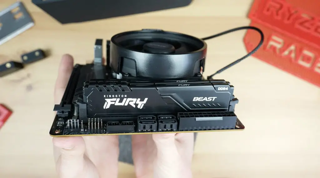
Then we can add our RAM to the two RAM slots, and add our SSD.
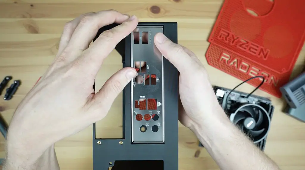
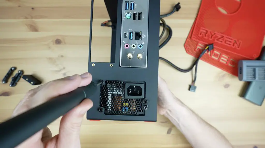
We can then push our faceplate into the case cutout and mount the motherboard on the standoffs, securing it with some M3 nylon screws.
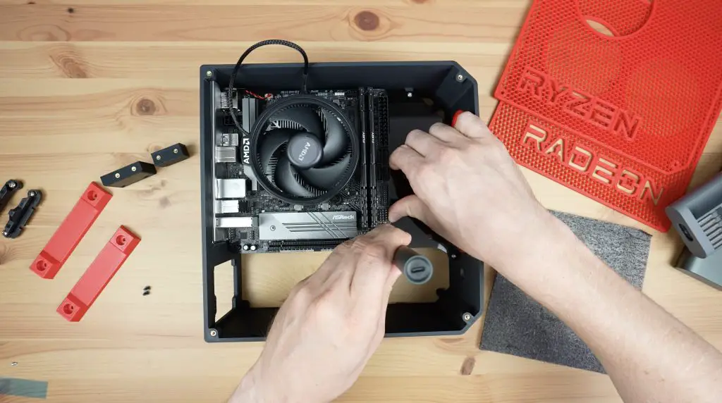
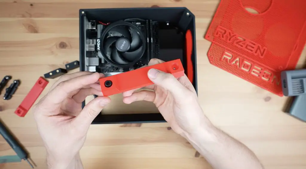
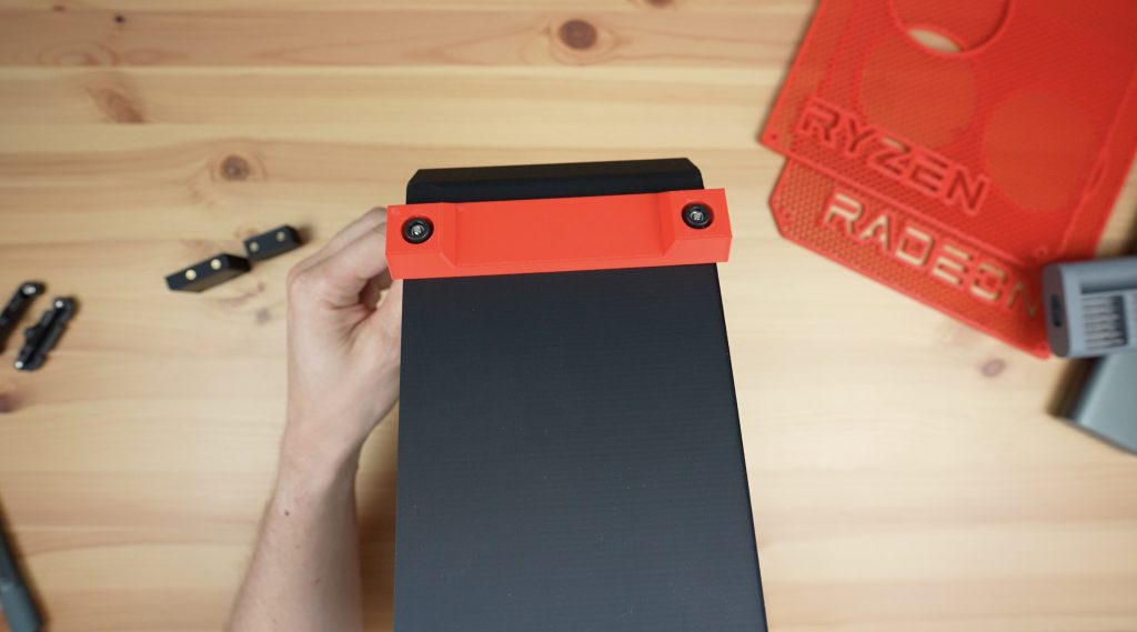
Before we add in the power supply, we need to install the legs and add the riser cable for the GPU. The legs are held in place with some M3x12mm button head screws and M3 nuts which go through some rubber feet for vibration isolation. The head of the M3 button head screw sits in the recess in the base of the case and the nut goes on the underside of each foot.
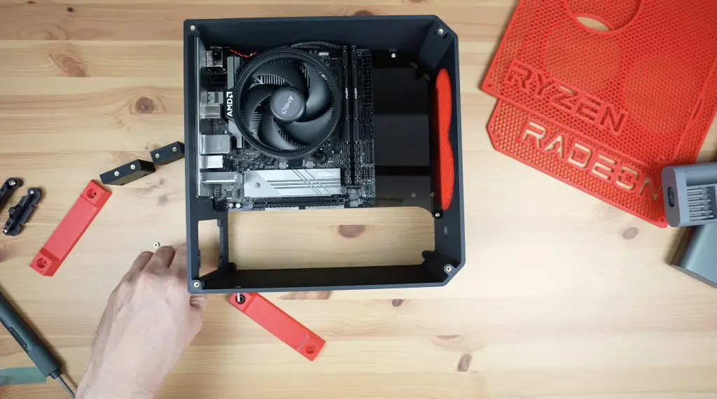
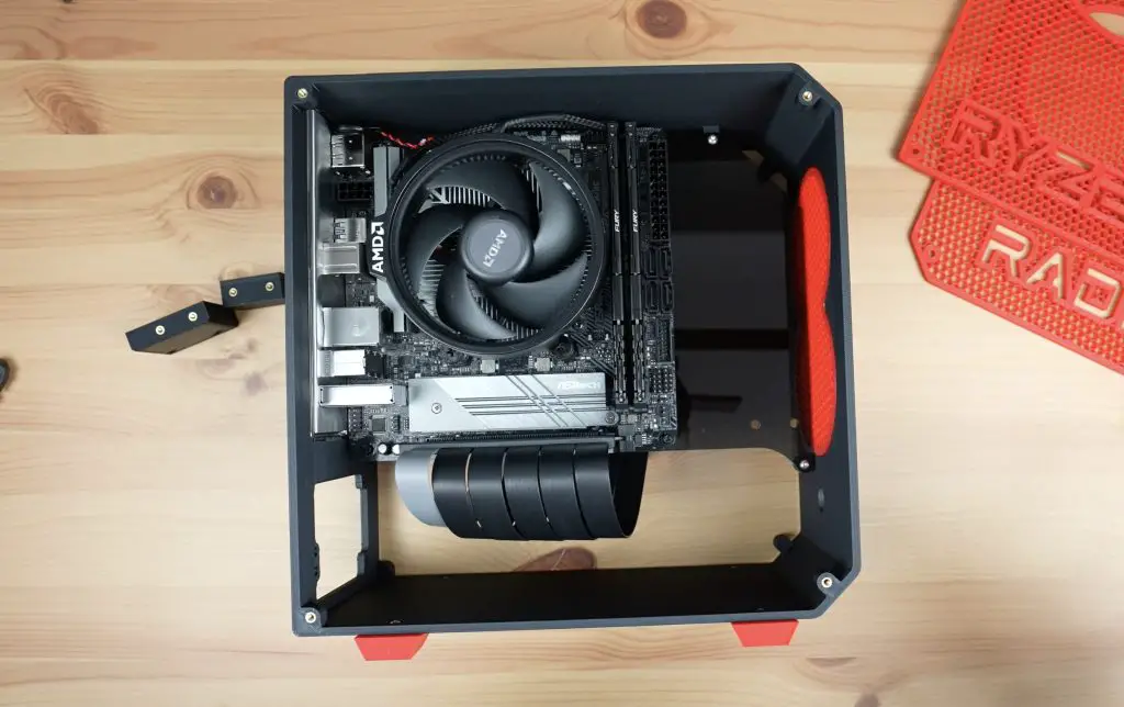
The riser cable plugs into the PCIe slot and then runs under the centre panel and to the GPU side of the case.
The power supply goes in underneath the motherboard and is held in place with four included screws at the back.
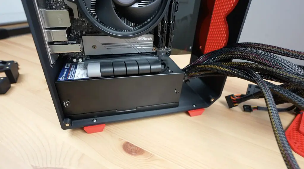
Problems…
With the motherboard and power supply in place, the graphics card gets mounted on the opposite side.
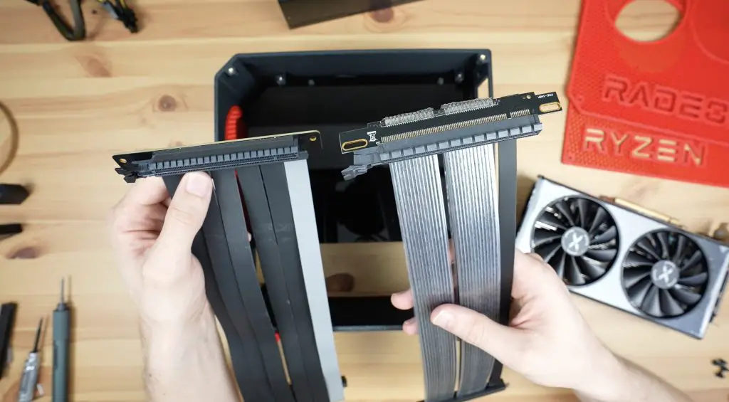
At this stage, I found my first issue. I hadn’t considered that the PCIe riser cable has quite a large plug on it and this makes the depth of the card a lot more than what I had allowed for. Even if I remove part of the centre panel, there isn’t even enough room between the card and the motherboard for this size plug.
I ordered a second one with a straight connector instead of a 90-degree one. This improved the depth issue but was then too wide for the space in the case. I removed the plastic shroud around the PCB joints and this allowed just enough room for it to fit into the case. This obviously puts strain on the soldered joints, which is not ideal, but I don’t plan on moving the computer around much so it shouldn’t be an issue.
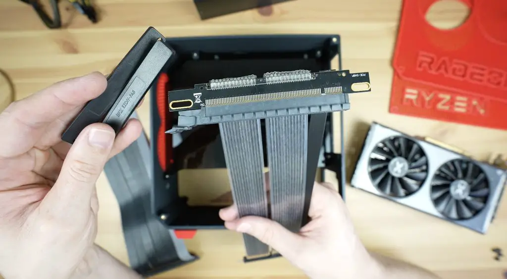
I’m going to leave it like this in my build as changing the card position would mean having to reprint all of the case components and I’m pretty sure I don’t have enough power left for that. The best solution would be to find a more compact 90-degree riser and allow for a cutout in the centre panel behind the motherboard for some additional clearance.
The card is held in place with a few brackets. The main one at the back is secured with two M3x16mm screws and then the card is screwed onto the bracket with M3x8mm screws. Then the one at the top clamps the card with another M3x16mm screw.
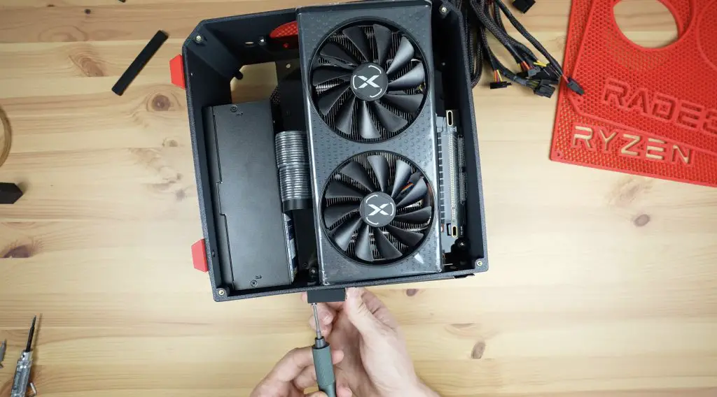
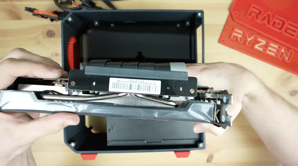
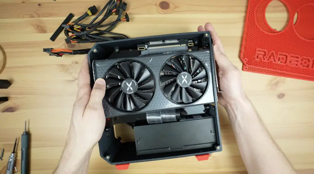
I was going to put this inside support in place with some M3x8mm screws and have the GPU rest on it. But I’m rather going to use these holes to zip-tie the GPU to pull it down into the case.
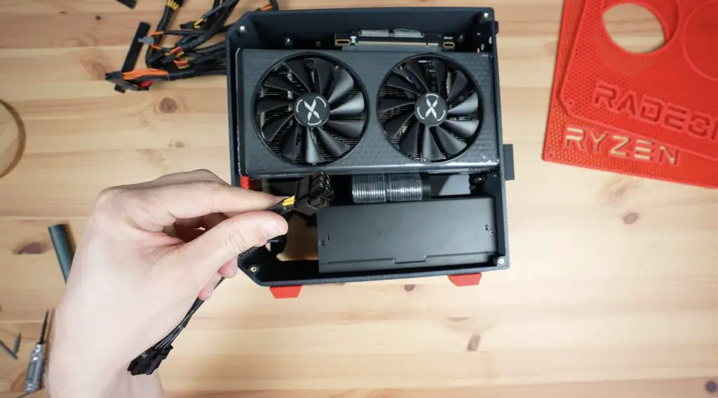
We can also plug our power supply into it.
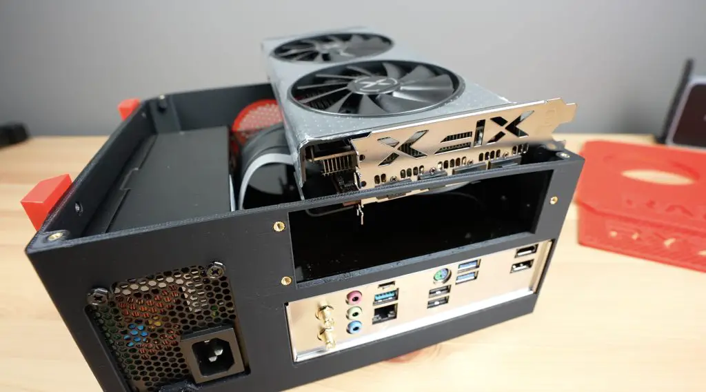
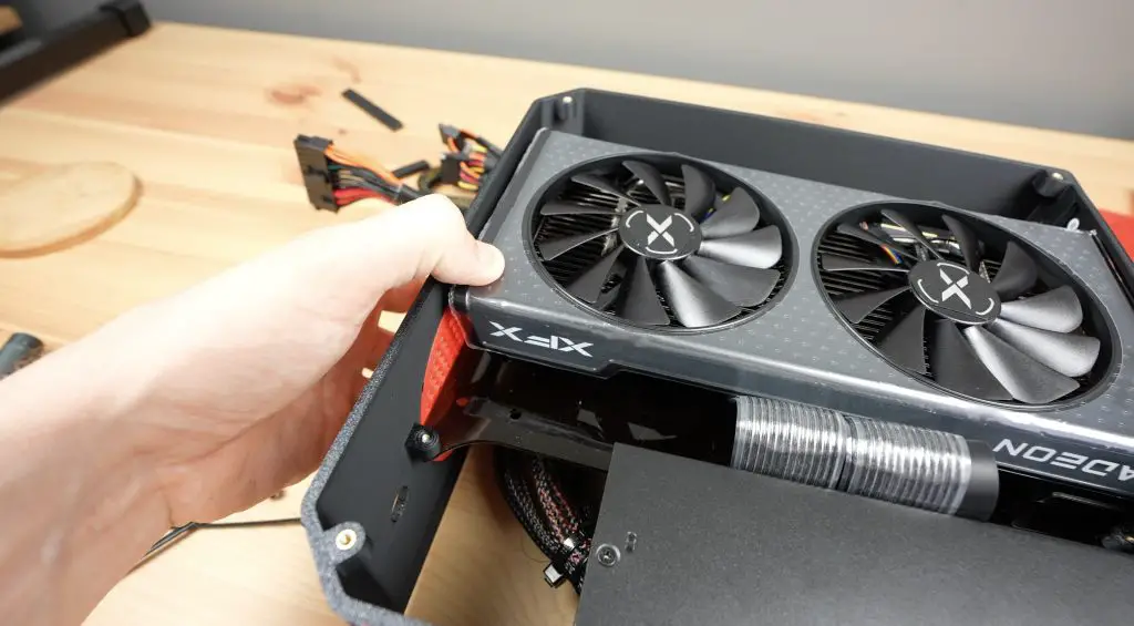
It’s a tight fit, the graphics card only just makes it into the case but I like that it’s a nice compact build.
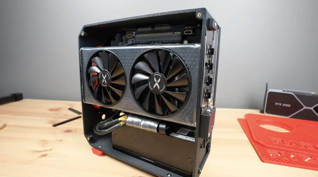
Lastly, let’s add the power button to the front of the case. I’ve pre-soldered leads to it and we can plug them into the motherboard pins.
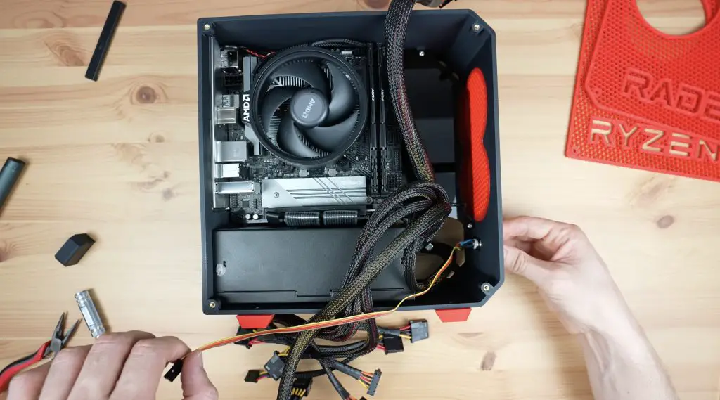
Now we can plug the power supply connections into the motherboard and close it up.
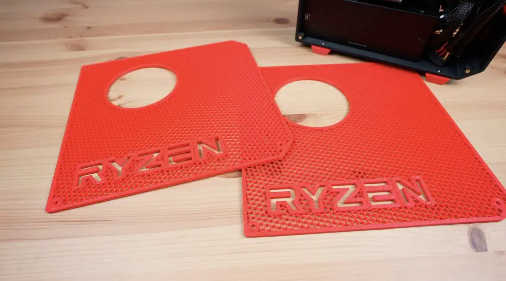
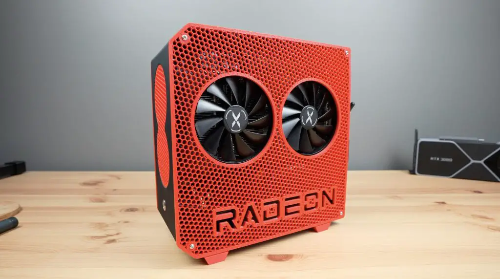
The side panels are also both held in place with some M3 button head screws. The graphics card side aligns really well with the fans but it looks like my guess on the motherboard side was a little off.
I’m going to tweak that by a few millimetres and get it printed again with my remaining charge, I’ve got 39% left and these panels used less than 10% each to print so I think that’s worthwhile.
The new panel is now made up and we’ve only used an additional 7% so I’m really happy with that. It looks like it lines up perfectly this time.
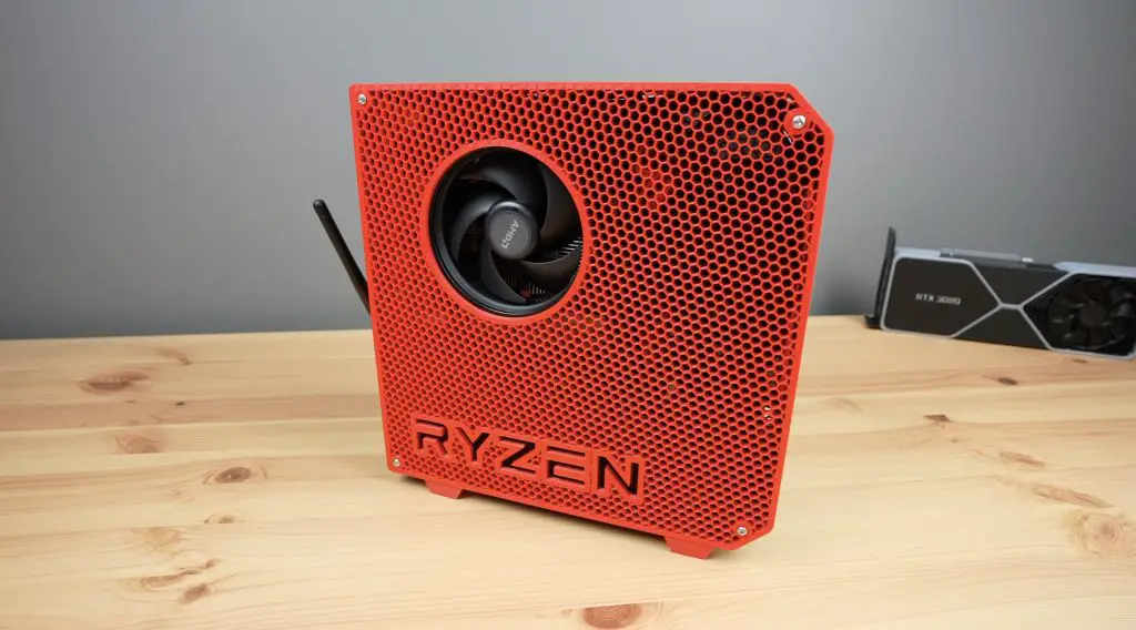
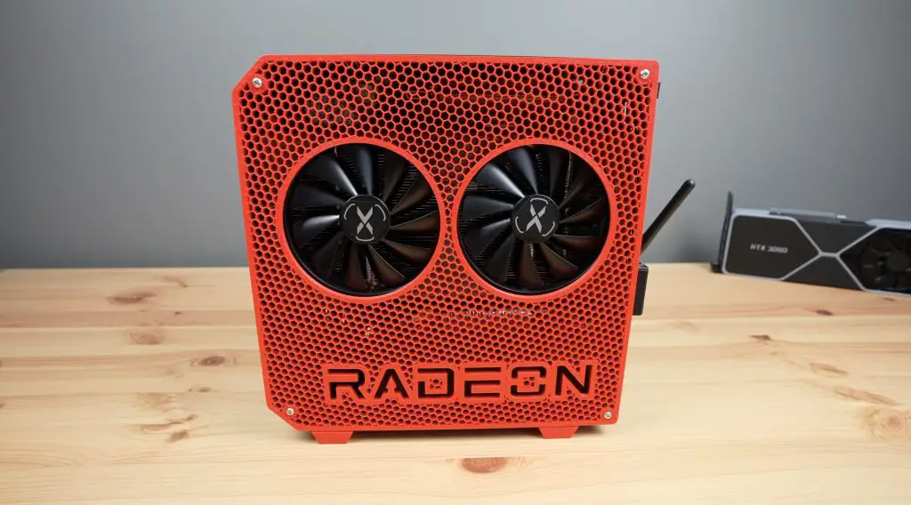
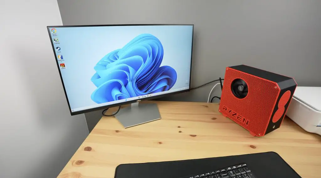
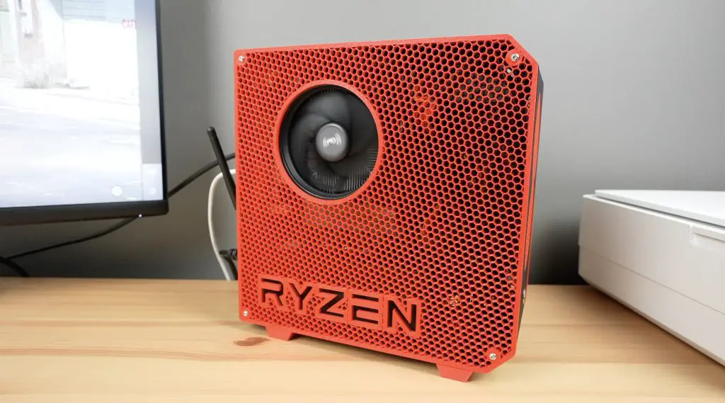
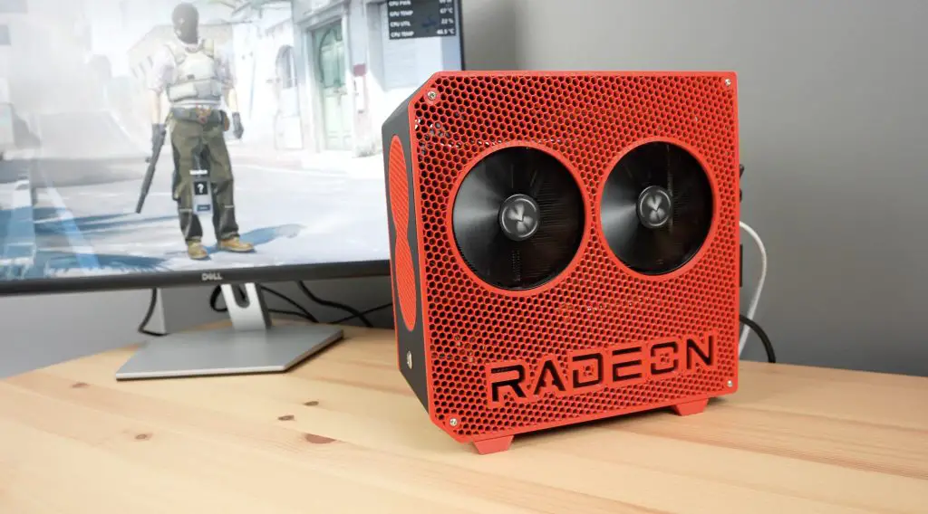
Assembly Of The Mini ITX PC Is Complete
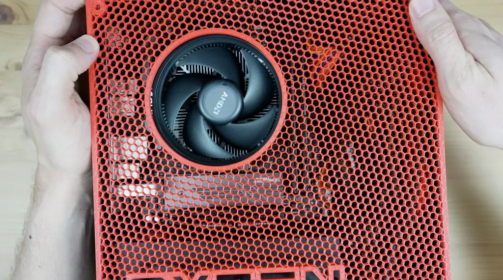
With the side panels in place, the assembly of the mini ITX computer is now complete and I think it has come out looking great!
Setting Up & Testing The Computer
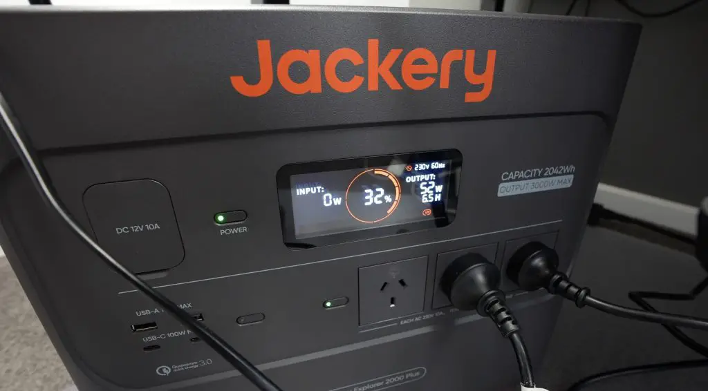
Now we need to set up the BIOS and install windows. I’ll do that with the computer running off the Explorer 2000 as well. In the BIOS, we can see we’ve got our Ryzen 5 processor detected as well as our two 8GB sticks of RAM and we can see our 1TB SSD.
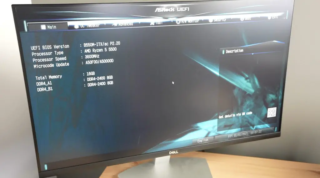
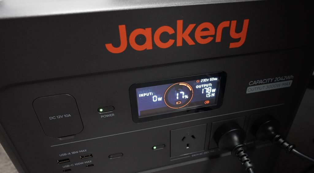
We’ve got 32% remaining and I’m drawing about 50W with the computer and monitor running off it but it is essentially at idle without an OS running.
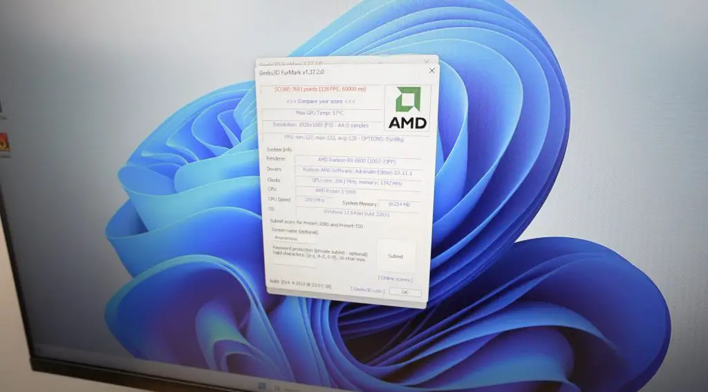
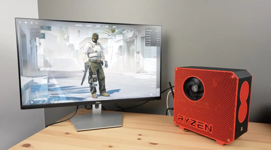
With Windows installed on the mini ITX computer, let’s try running Furmark at 1080P.
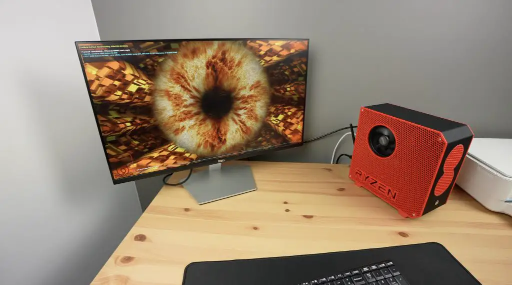
I get a score of 7691, with a maximum GPU temperature of 57 degrees and a total system power draw of about 160-170W. So there’s definitely a lot of room for overclocking. I ran the test two more times and still got an average score of around 7700 and the GPU temperature increased to a maximum of 64 degrees.
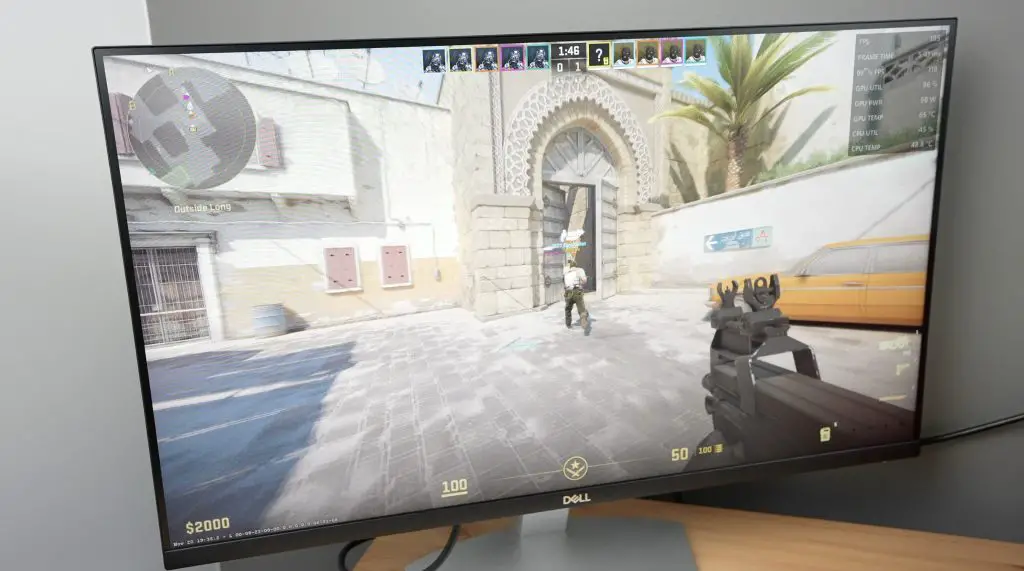
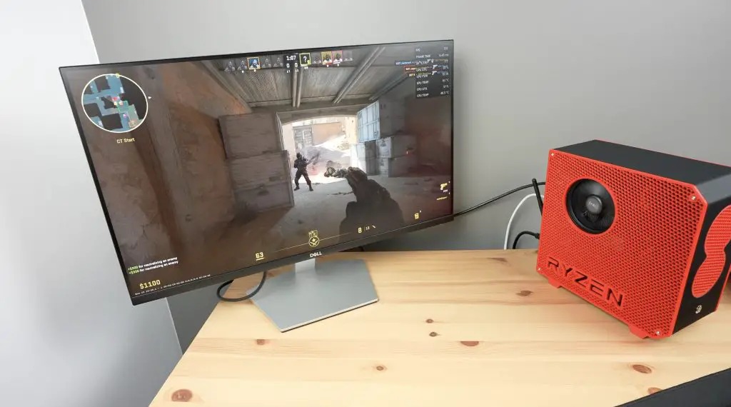
Running Counterstrike 2 at 1080P with all settings on Very High, we get between 150 and 200 fps. This is pretty good for this size computer. The power draw is also a little under 180W.
Final Thoughts On The Project & Jackery Solar Generator 2000 Plus
So I managed to design, print, assemble and configure a mini ITX computer using a single charge of the Solar Generator 2000 Plus. I even had 17% to spare, and better yet, the charge was free using solar power.
Check out Jackery’s web store if you’re interested in getting your own Solar Generator 2000 Plus kit. I think they’re really useful to have around the house or to take on day trips or camping trips for portable power. It’s quiet and clean, and power is essentially free with the solar panel.
Let me know what you think of the computer build in the comments section below. Let me know if you have a go at printing and building your own mini ITX PC as well. I’ve tried to keep the design generic enough that you’ll be able to use different components if you’d like to. I’ve included solid side panels as an option if you use a different cooler or GPU so that you don’t have the fan cutouts in the wrong places.
Hey Michael,
thank u for sharing your project, I found it very interesting.
I have a question, acrylic centre panel is not inherently antistatic, is it safe to use in a mini itx build? or should we use something more antistatic?