Today we’re going to be building a wireless outdoor weather station that takes temperature, humidity, barometric pressure, light and wind speed readings. The data is then posted to the cloud and can be accessed through a Thingspeak dashboard on an internet-connected computer, tablet, or mobile phone.
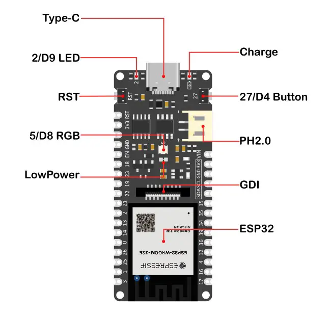
I’m going to use a development board from DF Robot called a Firebeetle ESP32-E IoT. I’ve chosen this particular board because it is inherently designed for low-power applications and can be powered by a lithium-ion battery directly. It’s got an onboard battery plug and supports charging through the USB C port.
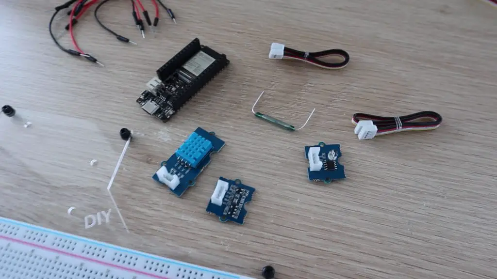
For the sensors, I’m going to be using grove sensors by Seeed Studios. They integrate all of the required supporting components onto the sensor, so you just need to make the connections between each sensor and your microcontroller. They use 4-wire grove cables to plug into supported hats and boards, like the Arduino MKR IoT Carrier board. I’m going to modify one end of each cable to make up a harness that plugs into the pins on the Firebeetle board.
Update: I’ve made some upgrades to this weather station since building it, you can have a look at these on my follow up guide.
Here’s a video of my build, read on for the full step by step instructions:
What You Need To Build Your Own Weather Station
- Firebeetle ESP32-E IoT Development Board – Buy Here
- Grove Sensors & Cables (Beginner Kit I Used) – Buy Here
- Reed Switch – Buy Here
- Neodymium Magnets – Buy Here
- Lithium Ion Battery Pack (better than my one) – Buy Here
- 3D Print Resin, White PLA Style – Buy Here
- M5 Button Head Screw & Nuts – Buy Here
- Bearings – Buy Here
- Header Pins – Buy Here
- Breadboard Jumpers – Buy Here
Equipment Used
- Voxelab Proxima 6.0 3D Printer (Amazon) – Buy Here
- Voxelab Proxima 6.0 3D Printer (Voxelab Direct) – Buy Here
- Fluke Multimeter – Buy Here
- TS100 Soldering Iron – Buy Here
- Dremel Versatip Heat Gun / Soldering Iron – Buy Here
Some of the above parts are affiliate links. By purchasing products through the above links, you’ll be supporting my projects, with no additional cost to you.
How To Make Your IoT Weather Station
Prepare Your Components
Lets start by removing the grove sensors we’re going to be using from the Grove Beginner Kit. You’ll need to cut through the tabs that join the sensors to the surrounding board. I used a sharp craft knife to cut each side and I then pushed the sensors out.
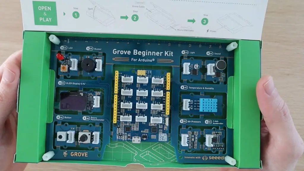
We’re going to use the pressure sensor that uses I2C communication, the DHT11 sensor that uses a digital pin and the light sensor that uses an analogue pin. You can leave the other sensors in place as we’re not going to be using them in this project.
We’re also going to make up an anemometer or wind speed sensor on top of the weather station that uses a reed switch to trigger an interrupt routine for each rotation.
Next, we need to prepare the Firebeetle board. It has a small jumper on it which DF Robot recommend breaking if you’re going to be using the board for low power applications. I couldn’t find any information in the documentation on exactly what this does or disables but I presume it disables things like the on-board power led in order to save power.
Assemble The Components On A Breadboard
This step is not required, but it is helpful to check that your sensors and connections are working properly before soldering the wiring harness. So let’s assemble the components on a breadboard to test the connections to each sensor and to get the code working.
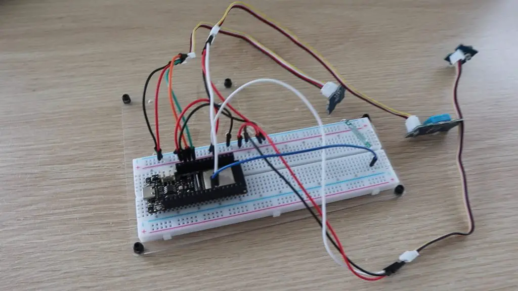
I’ve connected each of the sensors as follows:
- Pressure Sensor to I2C Interface
- VCC – 5V
- GND – GND
- SCL – SCL
- SDA – SDA
- DHT11 Temperature & Humidity Sensor to Pin 14
- VCC – 5V
- GND – GND
- Sig – Pin 14
- Light Sensor to Pin 36
- VCC – 5V
- GND – GND
- Sig – Pin 36
- Reed Switch to Pin 0
- Side 1 – GND
- Side 2 – Pin 0
You should be able to push the end of a male jumper into the grove connectors to pick up on each required wire. Make sure that you pick up the correct wires by tracing the wire colours back to the sensors.
Program The Firebeetle Board
Now that the sensors are connected to our board, we can write up a sketch to take readings from the sensors and post the data to Thingspeak. Between readings, we’ll put the ESP32 into deep sleep mode in order to save power. This shuts down the WiFi and Bluetooth communication modules as well as the CPU.
The Firebeetle board can be programmed in the Arduino IDE by adding the Firebeetle series of boards as an additional board type through the boards manager tool.
Here is the sketch:
//Weather Station
//The DIY Life by Michael Klements
//11 August 2021

#include <Wire.h>                                                   //Import the required libraries
#include "DHT.h"
#include "Seeed_BMP280.h"
#include <WiFi.h>
#include "ThingSpeak.h"

#define lightSen 36                                                 //Define pin numbers
#define windSen 0
#define uS_TO_S_FACTOR 1000000ULL                                   //Conversion factor for micro seconds to seconds
#define TIME_TO_SLEEP  570                                          //Time ESP32 will go to sleep (in seconds) - 9.5 minutes

DHT dht(14,DHT11);                                                  //DHT and bMP sensor parameters
BMP280 bmp280;

WiFiClient client;                                                  //WiFi connection details
char ssid[] = "WIFI SSID";                                          //WiFi Name
char pass[] = "WIFI PASSWORD";                                      //WiFi Password

unsigned long myChannelNumber = YOUR CHANNEL ID;                    //Thingspeak channel number
const char * myWriteAPIKey = "YOUR WRITE API KEY";                  //Thingspeak API write key

int light = 0;                                                      //Variables to store sensor readings
int temp = 0;
int humid = 0;
int pressure = 0;
int wind = 0;

unsigned long firstMillis = 0;                                       //Timers for the wind speed calculation
unsigned long lastMillis = 0;
unsigned long lastIntTime = 0;
int counter = 0;                                                     //Counter to keep track of the number of wind speed revolutions

void IRAM_ATTR isr ()                                                //Interrupt routine, run with each reed switch interrupt
{
  unsigned long intTime = millis();
  if(intTime - lastIntTime > 150)                                    //Debounce the reed switch input
  {
    if (counter == 0)
      firstMillis = millis();
    counter++;                                                       //Count each revolution
    lastMillis = millis();
    Serial.println(counter);
  }
  lastIntTime = intTime;                                             //Capture the first and last revolution time
}

void setup()                                                         //Setup function - only function that is run in deep sleep mode
{
  Serial.begin(9600);
  if(!bmp280.init())                                                 //Connect to pressure sensor
  {
    Serial.println("bmp280 init error!");
  }
  pinMode(lightSen, INPUT);                                          //Define pin functions
  pinMode(windSen, INPUT_PULLUP);
  attachInterrupt(windSen, isr, FALLING);                            //Define interrupt pin
  WiFi.begin(ssid, pass);                                            //Connect to WiFi network
  while (WiFi.status() != WL_CONNECTED)
  {
    delay(500);
    Serial.print(".");
  }
  Serial.println("");
  Serial.println("WiFi connected");
  esp_sleep_enable_timer_wakeup(TIME_TO_SLEEP * uS_TO_S_FACTOR);     //Initialise deep sleep mode parameters
  ThingSpeak.begin(client);                                          //Initialise ThingSpeak
  delay(10000);                                                      //Wait for wind speed readings to be taken
  recLight ();                                                       //Take readings from other sensors
  recTempHumid ();
  recPress ();
  calcWind ();
  counter = 0;
  Serial.print("Light: ");                                           //Display readings on serial monitor
  Serial.println(light);
  Serial.print("Temp: ");
  Serial.println(temp);
  Serial.print("Humidity: ");
  Serial.println(humid);
  Serial.print("Pressure: ");
  Serial.println(pressure);
  Serial.print("Wind: ");
  Serial.println(wind);
  updateThingSpeak ();                                               //Post the data to Thingspeak
  Serial.println("Going to sleep now");
  Serial.flush();
  esp_deep_sleep_start();                                            //Enter sleep mode
}

void loop()                                                          //Loop function - unused
{

}

void recLight ()                                                     //Function to record the light level
{
  light = analogRead(lightSen);
}

void recTempHumid ()                                                 //Function to record the temperature and humidity
{
  temp = dht.readTemperature();
  humid = dht.readHumidity();
}

void recPress ()                                                     //Function to record the pressure
{
  pressure = bmp280.getPressure()/100;
}

void calcWind ()                                                     //Function to calculate the wind speed
{
  int ave = 5000;
  if(counter != 0)
    ave = (lastMillis - firstMillis)/counter;
  Serial.print("Average Tick Time: ");
  Serial.println(ave);
  if (ave < 200)
  {
    ave = 200;
    wind = map (ave,200, 4000, 16, 3);
  }
  else if (ave > 4000)
    wind = 0;
  else
  {
    wind = map (ave,200, 4000, 16, 3);
  }
}

void updateThingSpeak ()                                             //Function to post data to Thingspeak
{
  ThingSpeak.setField(1, light);
  ThingSpeak.setField(2, temp);
  ThingSpeak.setField(3, humid);
  ThingSpeak.setField(4, pressure);
  ThingSpeak.setField(5, wind);
  int x = ThingSpeak.writeFields(myChannelNumber, myWriteAPIKey);
  if(x == 200)
  {
    Serial.println("Channel update successful.");
  }
  else
  {
    Serial.println("Problem updating channel. HTTP error code " + String(x));
  }
}Before uploading the code to your Firebeetle, you’ll need to add your network and Thingspeak channel details.
Your network name (SSID) and password need to be added to the fields in lines 20 and 21.
You’ll also need to create an account on Thingspeak and then create a channel for your data. You’ll then be able to generate a write API key for your channel. The API key is effectively the password your ESP32 uses to be able to post data to your Thingspeak channel, so that Thingspeak knows that the data is coming from the correct source. Add your channel name to line 23 and your write API key to line 24.
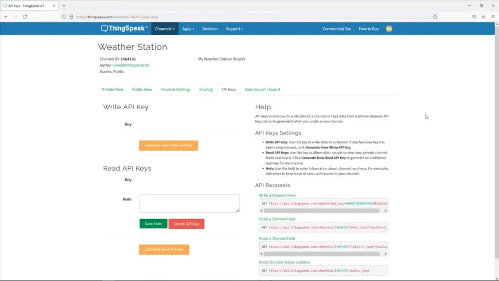
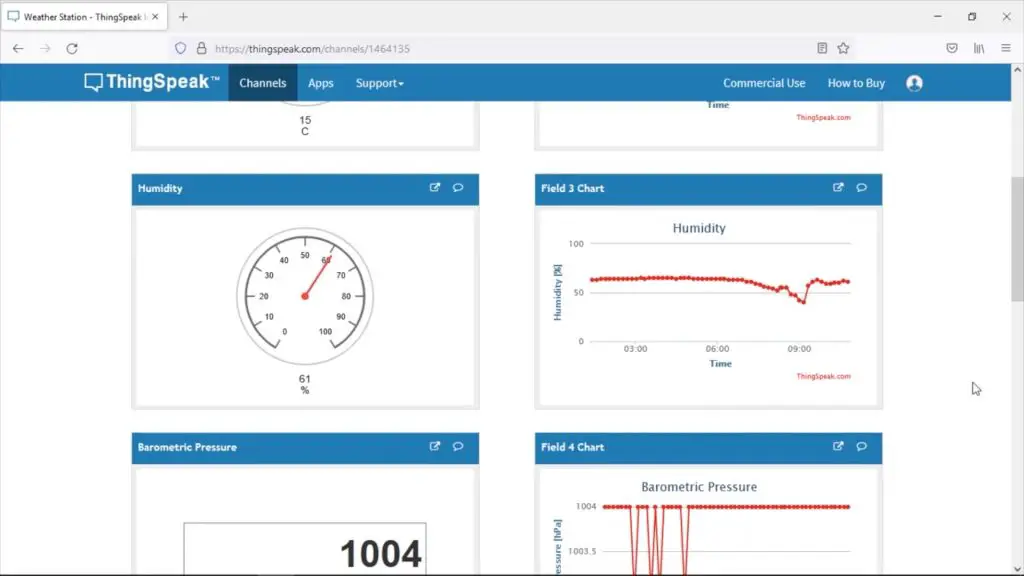
On my Thingspeak account, I’ve created a weather station channel and then made a dashboard to view the channel data which I’ve put a gauge and a trend chart onto for each field.
It’s important to keep track of which fields are receiving which data sets from your weather station, they are posted to a field number in your code (lines 136 to 140) and you’ll need to use the field number to display data on your charts and gauges on your dashboard.
You’ll notice that all of the code is in the setup() function and that the loop() function is left empty. This is because the ESP32 only runs the setup() function when operating in deep sleep mode, so only the code in this function is executed each time it wakes up.
In the setup function, connections are made to the sensors and the pin modes are defined. The board then connects to the WiFi network and starts a new Thingspeak client. There is then a 10 second delay to allow the anemometer to increment the reed switch counter in order to calculate the current wind speed. The board then takes readings from all of the other sensors, calculates the wind speed based on the number of revolutions and the time, then posts the data to Thingspeak and enters deep sleep mode. I’ve added some output lines to the Serial monitor to assist with debugging while you’ve got your board connected to your computer.
The entire wakeup cycle takes about 20-30 seconds to complete including the 10 seconds that the ESP32 waits to measure the wind speed data.
Soldering The Wiring Harness
To make the weather station a bit more resilient, it’s a good idea to make up a permanent wiring harness to connect the sensors to the Firebeetle board.
I cut the ends off of one side of the grove cables and soldered these along with two female jumpers for the reed switch onto some male header pins.
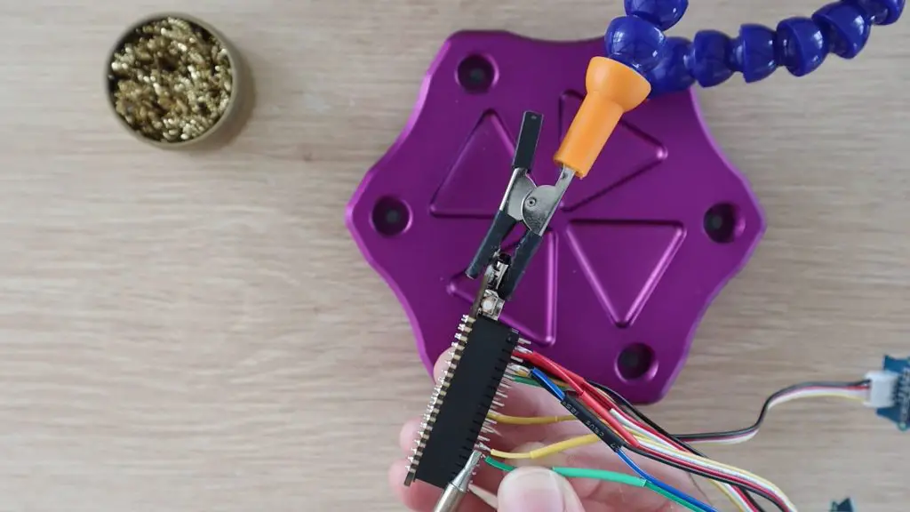
The grove plugs are still on the other end of the grove leads, so they can be plugged in or removed as needed.
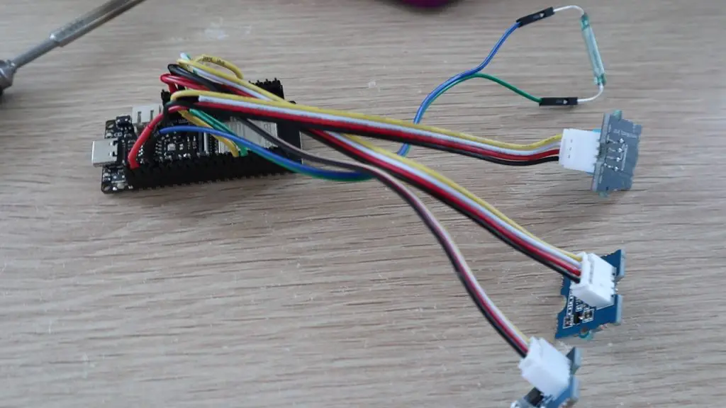
I also marked the plugs with a TH, P, and L to keep track of which sensor they plug into.
Designing and 3D Printing The Weather Station Housing
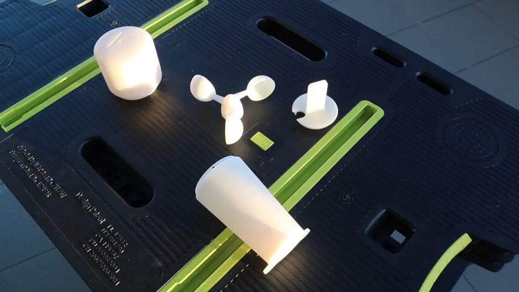
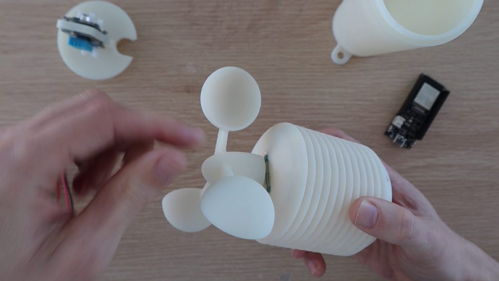
Next, we need to design a housing to protect the components when they’re mounted outdoors. The sensors can’t be completely enclosed as this will interfere with their accuracy, but they need to be protected from direct sun and rain. I wanted the weather station to be as compact as possible, so I wanted to integrate the sensors and the anemometer into a single assembly.
The design I came up with housed the ESP32 and battery in the base, with the sensors in a vented centre compartment and the anemometer on top. I used Fusion 360 to model the four components that make up the housing.
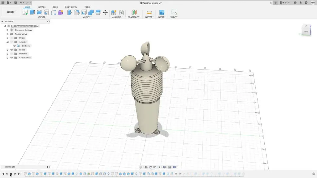
Download the 3D Print Files – Weather Station
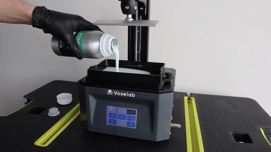
I wanted to 3D print the components in resin so that I could print the sensor housing as a single piece and I wouldn’t have to build it up with each ring as an individual print. You can experiment with printing the components on an FDM printer as well, you’ll just need to play around with the orientation and print speeds to get right.
I’m not yet sure how well resin prints will hold up in the sun. I’ve done a bit of research on it and most articles I’ve found say that it’s a bad idea, listing brittling and UV damage as likely to lead to failures, but I’ve also seen a couple of tests where people have actually left prints outside through sun, rain, and snow and they didn’t seem to have any visible damage. So I thought I’d give it a try and see how long it lasts.
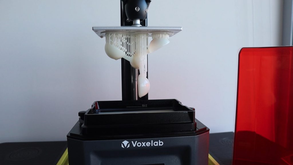
I printed them in regular pla style white resin, then cleaned them up and removed the supports. I printed the base and sensor holder vertically and the sensor housing at a 45 degree angle with supports.
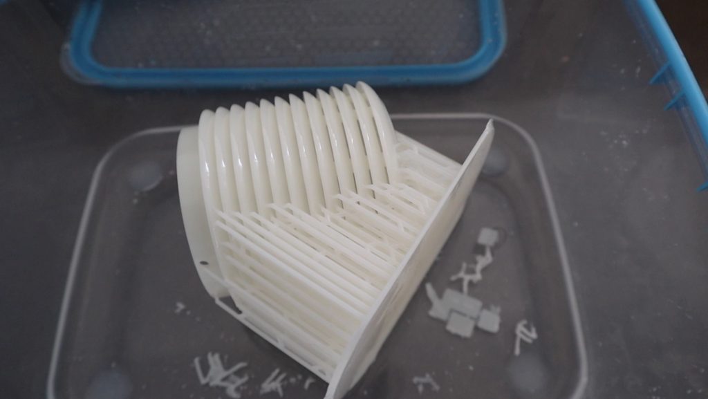
I allowed the parts to cure in the sun for a day as I don’t yet have a UV curing chamber.
I’ve recently reviewed the Voxelab Proxima 6 sla printer that I used for these prints. It’s a really good quality entry-level resin printer. If you’re looking at getting into sla printing I’d definitely recommend checking it out.
Now that all of the housing components are ready, we can start assembling the weather station.
Installing The Components In The Weather Station Housing
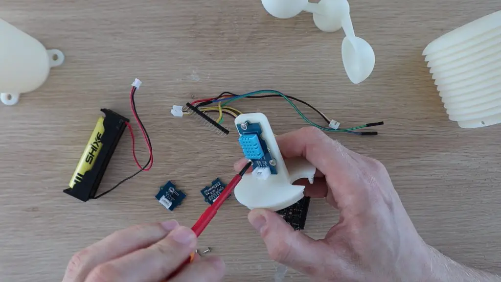
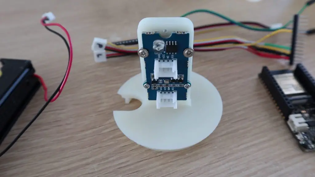
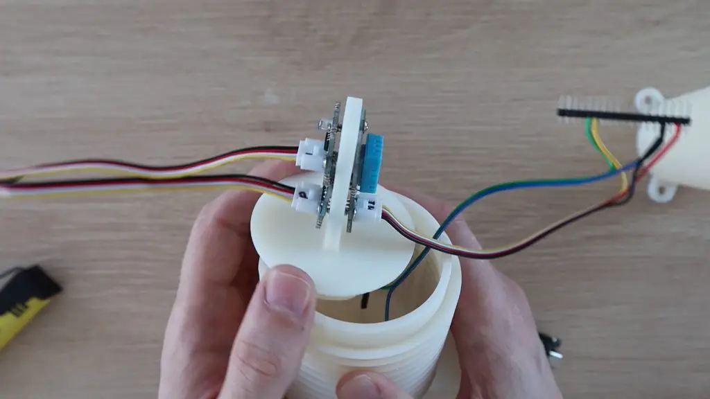
We’ll start out by mounting the temperature and humidity sensor on one side of the sensor stand. I’ve already added the mounting holes into the 3D print, so each sensor just needs to be screwed into place. I just used some small screws that I had lying around my workshop from some servos.
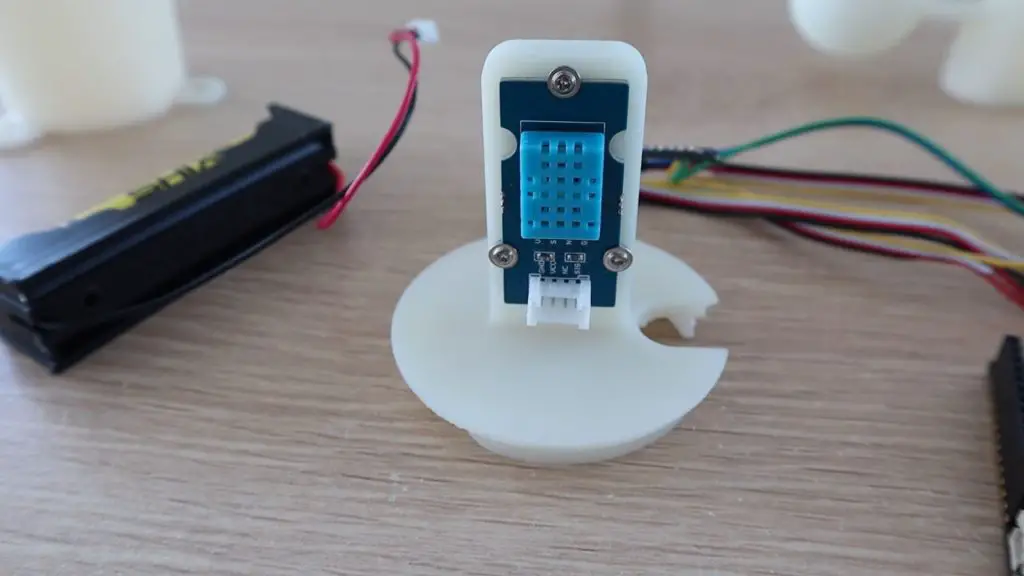
We can then mount the pressure and light sensors onto the other side of the stand.
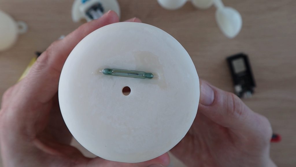
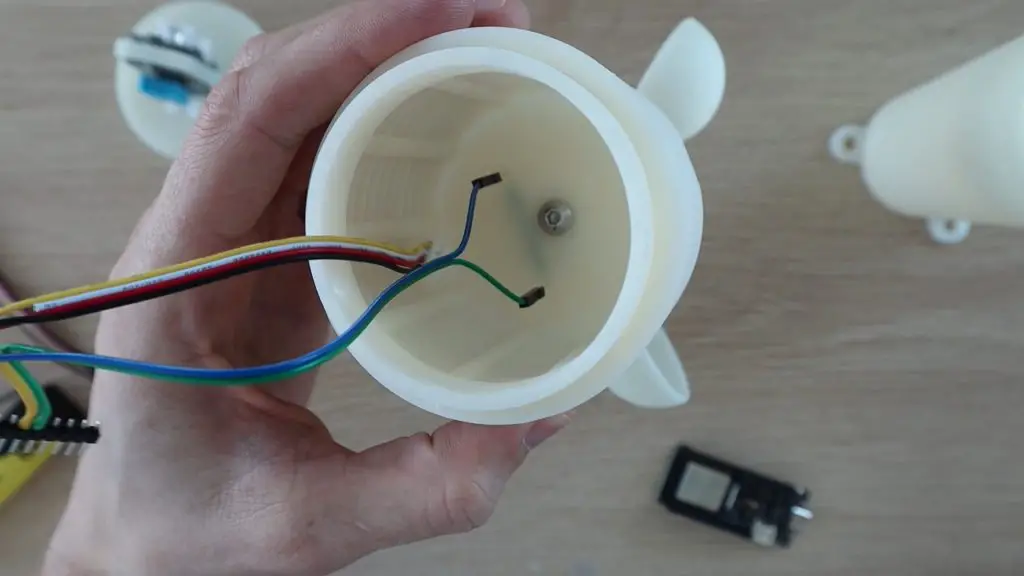
Next, let’s install the reed switch on top of the sensor housing. You’ll need to bend the legs 90 degrees to fit into the premade holes through to the inside of the housing. I added some print resin to fill up the void and seal the holes through the top and then cured it will a small UV light.
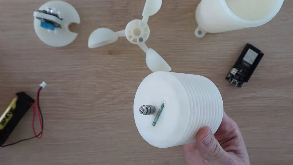
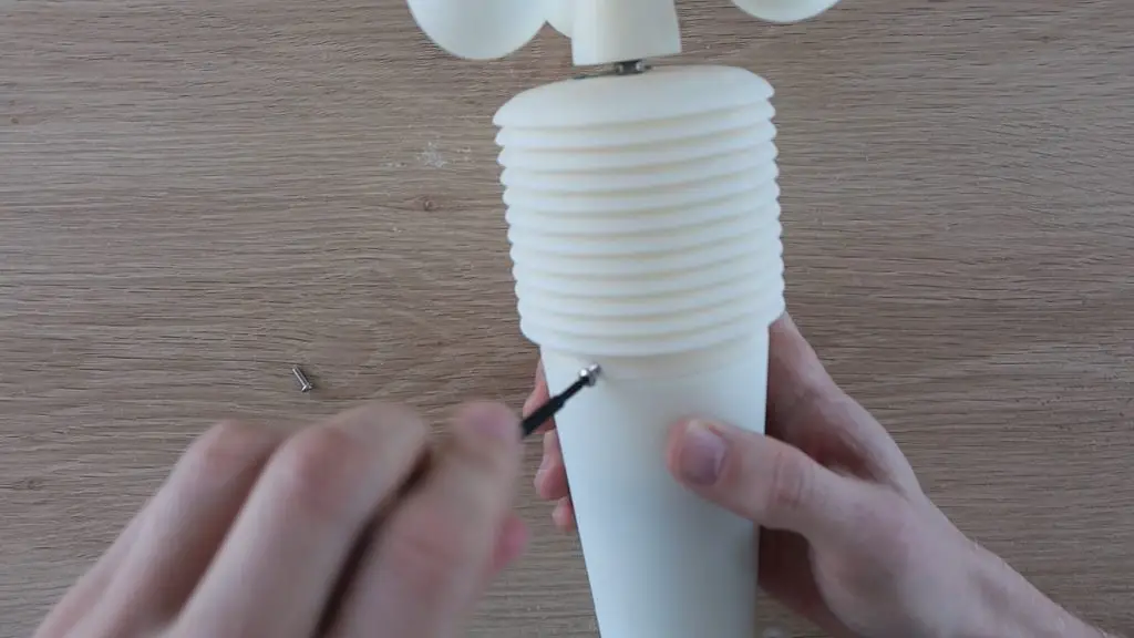
The anemometer is mounted onto the top of the weather station using an M5x20mm screw, two nuts and two small bearings.
Push the screw through the hole in the top (from the inside), then secure it with the first nut. Place the two bearings onto the screw and the second nut then holds them in place, but shouldn’t squash them.
We need to add a small stack of magnets into the anemometer to activate the reed switch on each turn. Push a couple (4-5) into one of the gaps so that they sit flush with the base of the anemometer.
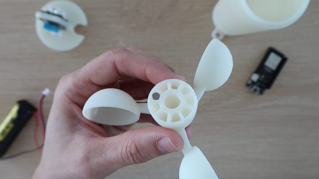
The anemometer is then just pushed onto the bearings. If your bearings are tight, put a drop of thin oil on them first and make sure that they’re not being clamped too firmly by the top nut. They should turn freely.
We can then plug the wiring harness onto the legs of the reed switch for the wind speed sensor.
Finally, connect the sensors to the Firebeetle board.
There is one last thing we need to check before putting the sensor housing on over the sensors, the power consumption.
How Long Will The Battery Last?
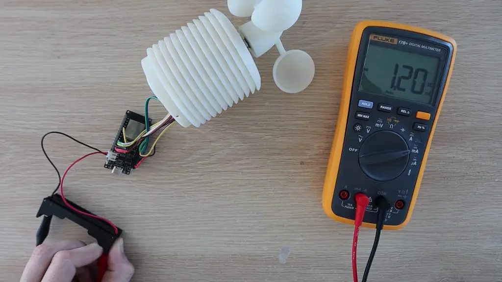
Since this project is battery-powered, we’d obviously like to know how long the battery is going to last. So, I measured the power consumption for the whole setup using a multimeter.
The board and sensors use about 30-60mA when running and this momentarily spikes to just over 120mA when connecting and posting data over WiFi.
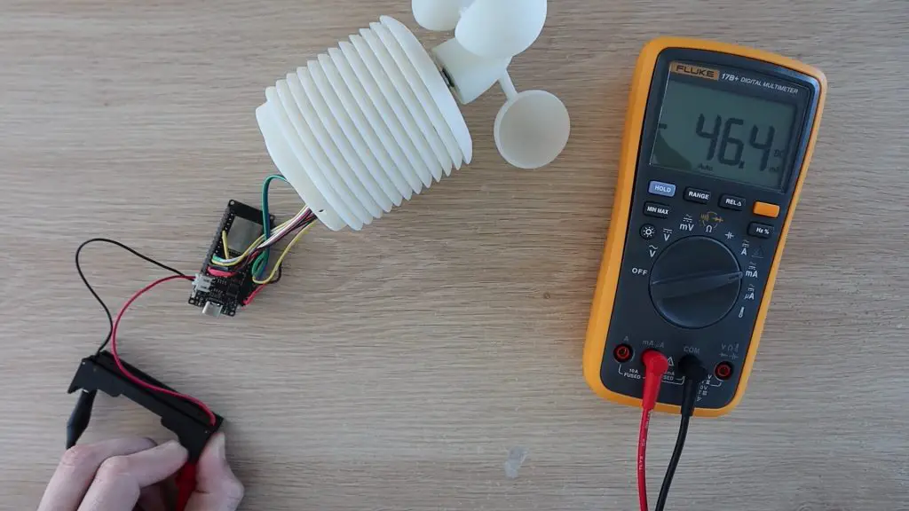
When in deep sleep, this goes down to about 1.2mA.
This is still higher than I was hoping for but seems to be related to the power being drawn by the components on the sensors in addition to the Firebeetle board. I’ll be looking into a way to use an optocoupler to turn the sensors on only when the board is awake.
With this setup, the weather station should run on a single 2500mAh battery for a little under 2 months. This is not too bad but is still a hassle to remember to charge. I could also get around this by adding a small solar panel to the weather station to charge it every day.
With that done, we can close up the base with three M3x8mm screws.
Testing The IoT Weather Station
The weather station can be mounted with some screws or cable ties through the feet in the base. Screws are a better long-term solution if you’ve got a suitable material to mount it onto.
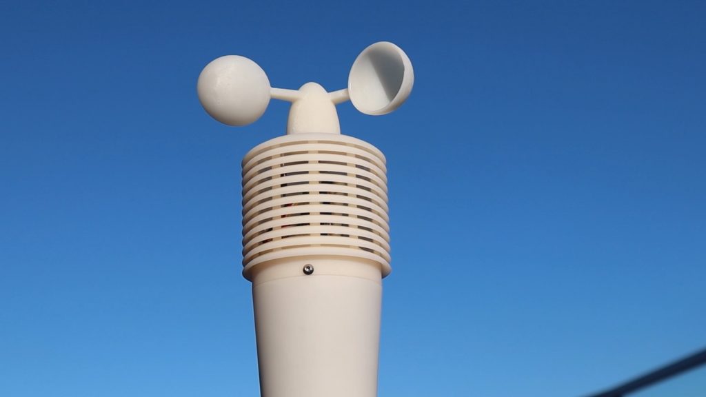
Now I just need to leave it out and see how well it records the weather.
After a couple of hours, it all looked like it was working well. As luck would have it, this was the most still weekend we’ve had in months, so there was no wind to test. There was a light breeze once or twice that got it turning, and it did register a reading, but this reading was way higher than the actual wind speed, so it needs some adjusting.
I’ll need to do some further testing on the actual wind speed to calibrate the anemometer, but for now it registers each revolution and is able to turn in a light breeze, which is a good start.
I then left it overnight.
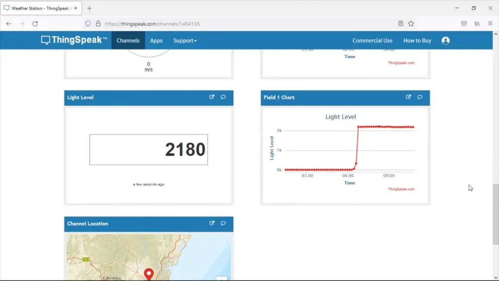
I got some consistent results overnight and the light sensor picked up the sunrise quite sharply. Again, there were one or two wind spikes in the morning, way higher than the actual wind speed would have been.
View the weather station dashboard here.
Overall I’m really happy with how it came out. I’ll post an update on how the resin print is holding up in a month or two’s time – if it doesn’t break before then. Hopefully, we’ll have a few windy days soon and I’ll then be able to adjust the timing to get reliable wind speed results too!
Let me know what you think of the weather station and what you would add or do differently in the comments section below. Enjoy the project!
Really nice. I’ve always wanted to try this kind of thing. The problem is that I made a small box with a sensor bmp180 humidity, temperature and pression. But with the rain and the wind. There were projection from the bottom and goes to end up destroying the sensor. I look forward to reading more. Know if it’s going with the storm and how to adjust the wind speed. Once done. I’m thinking of making it.
I’ll let you know how this one holds up. I couldn’t find any specific information on the design of the sensor housing, so the angles and gaps, etc. are all just best guesses. In a month or two I’ll probably have a good idea of what has worked well and what hasn’t.
I look forward to reading you. I read each article carefully. I prefer the blog format. To the video because I speak no English. I read a little. Otherwise I self-translate. Good suite in any case.
Hi Michael,
Once again, great project. Two friends and me started a similar project here in Singapore a few years ago, but we stopped when one of team members left the country. We had back then a little bit more of sensors, attempting to measure Singapore PSI index. Details here:
https://sashpi.wordpress.com/
I think the backend is still available, custom made, if you want to use it 🙂
Looking forward to an update on the case in terms of durability as well as water protection of its components. Thanks a lot for the constant project updates!
Best,
Miguel
Hi Miguel,
Thanks for the link, I’ll go check it out. I see someone else on Youtube has said that monitoring the PSI Index in Singapore is quite popular.
I’ll definitely post an update on the durability in a few months.!
Thanks again and keep well.
Hi Michael
> I wanted to 3D print the components in resin so that I could print the sensor housing as a single piece and I wouldn’t have to build it up with each ring as an individual print.
I want to understand what the difference here is between resin and fdm prints? Couldn’t you print the same model in one piece with FDM given that both methods need supports?
They both require supports, but the required supports are very different. A resin printer can print a suspended circle with a couple of point supports because the “print” is supported by the display while curing, the support is required to pull it off the display. An fdm printer can’t print a suspended circle without some form of support around the entire circumference and if you add point supports it’ll just drag straight lines between the supports so you’ll land up with the lower layers being hexagons (or other polygons). You could try print it on an fdm printer at an angle.
I have the initial part working. I’m using the BME sensor instead of the BMP. The BME does temperature, humidity, and pressure. So do we need the DHT sensor?
What exactly is the REED switch doing?