In this project, we’re going to be building a wireless robot car that uses mecanum wheels to enable omnidirectional movement. If you haven’t heard of mecanum wheels before, they’re tireless wheels with a series of rubberized rollers around the circumference.
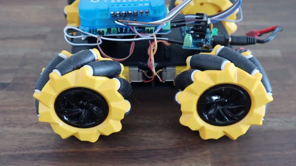
These rollers are typically at an angle of 45 degrees to the wheel’s axle line and opposing wheels are of the opposite hand. This enables the usual forward, backward and turning movements of standard wheels, but also allow unique translational movements horizontally and diagonally depending on which direction the wheels are turned.
We’re going to be using the Quantum Integration system to take inputs from a joystick controller and drive the motors. We’ll be using two Builder bases, one as a transmitter on the controller and one as a receiver on the robot car, so the starter bundle is perfect for this project.
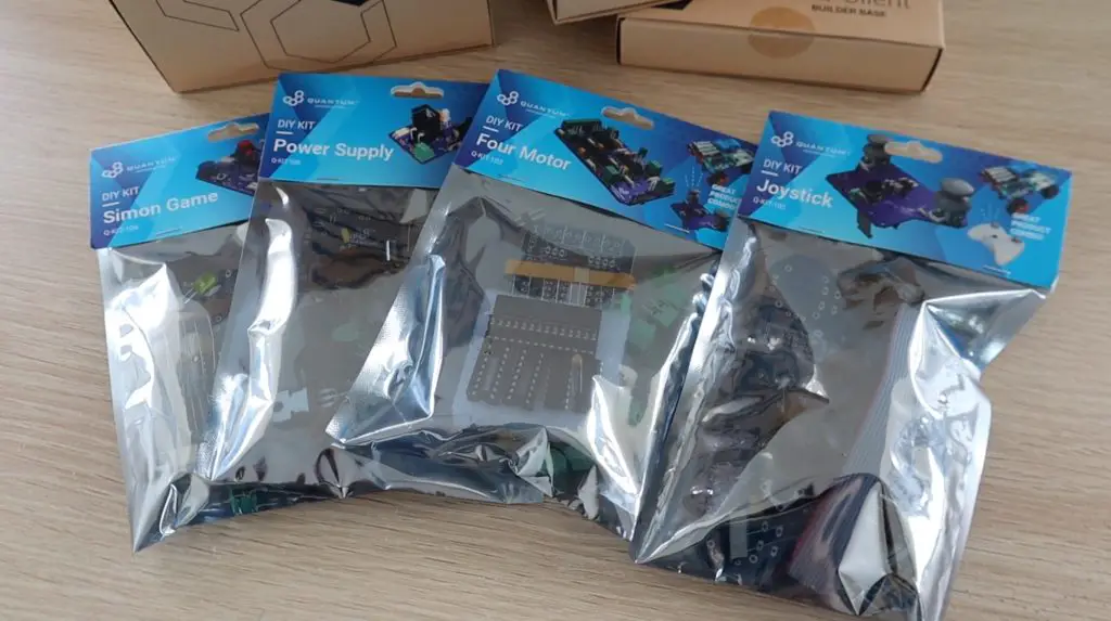
We’re also going to use three of their DIY PCB kits – the power supply, the four motor driver and the joystick controller.
Here is my project video, read on for the full written instructions:
What You Need For This Project
- Quantum Integration Starter Kit – Buy Here
- DIY Power Supply Kit – Buy Here
- DIY 4 Motor Driver Kit – Buy Here
- DIY Joystick Kit – Buy Here
- 4 DC Geared Motors – Buy Here
- 4 Mecanum Wheels (Ones I’ve Used) – Buy Here
- 4 Mecanum Wheels (Amazon Alternative) – Buy Here
- Breadboard Jumpers – Buy Here
You’ll also need some basic soldering tools to assemble your PCBs, these are the tools that I use:
- TS100 Soldering Iron – Buy Here
- Soldering Helping Hands – Buy Here
- Soldering Iron Tip Cleaner – Buy Here
Assembling The Robot Car
I’m going to use the same car that I’ve used for my previous obstacle avoiding robot and object tracking robot projects, but this time I’ll replace the Arduino with a Quantum Integration Builder Base.
If you’d like to 3D print the same chassis that I’ve used, use the below link to download the files. I printed them in black PLA with a 15% infill.
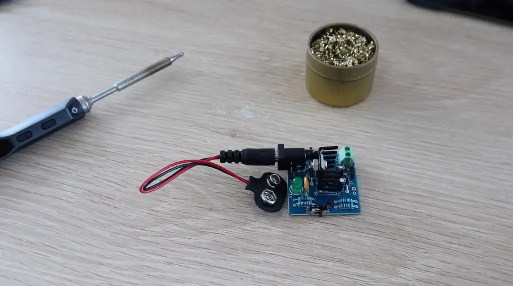
Let’s start out by assembling the power supply module. This module just takes a DC input of 7-12V provided through a 2.1mm barrel jack and converts it to 3.3V or 5V to be used by the Builder Base and Motor Driver.
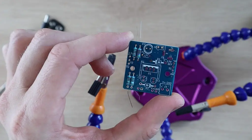
I’m going to be using a 3 cell LiPo battery to supply power to the car, but you can use three 18650 lithium-ion cells or 4 AA cells to power yours. It’s worth mentioning that 9V block batteries typically can’t produce enough current to drive four motors, so you’ll need something more substantial.
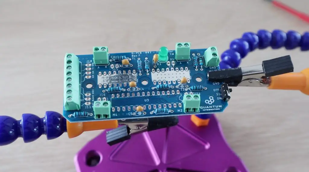
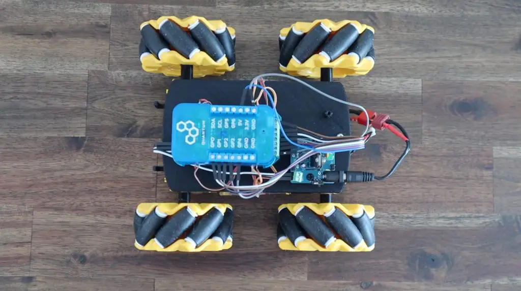
Next we’re going to assemble the Four Motor Driver kit. This kit features two L293D motor drivers along with a PWM expander and the supporting components required to independently drive up to four small DC motors, so it’s perfect for four-wheel drive robots.
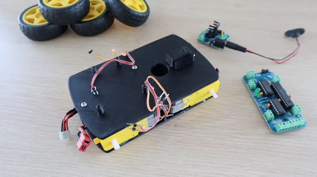
Once the motor driver is complete, we’re going to connect the motors to the driver and the driver to the builder base. This is done as per the project notes on the Quantum Integrate wiki, so it’s easy to follow.
If you’ve 3D printed your own robot chassis parts from my previous project, you’ll need to assemble your chassis and install the motors before you add the driver.
Connect the two wires from each motor to each of the motor terminal blocks as follows:
- Front Left – M1
- Front Right – M2
- Back Left – M3
- Back Right – M4
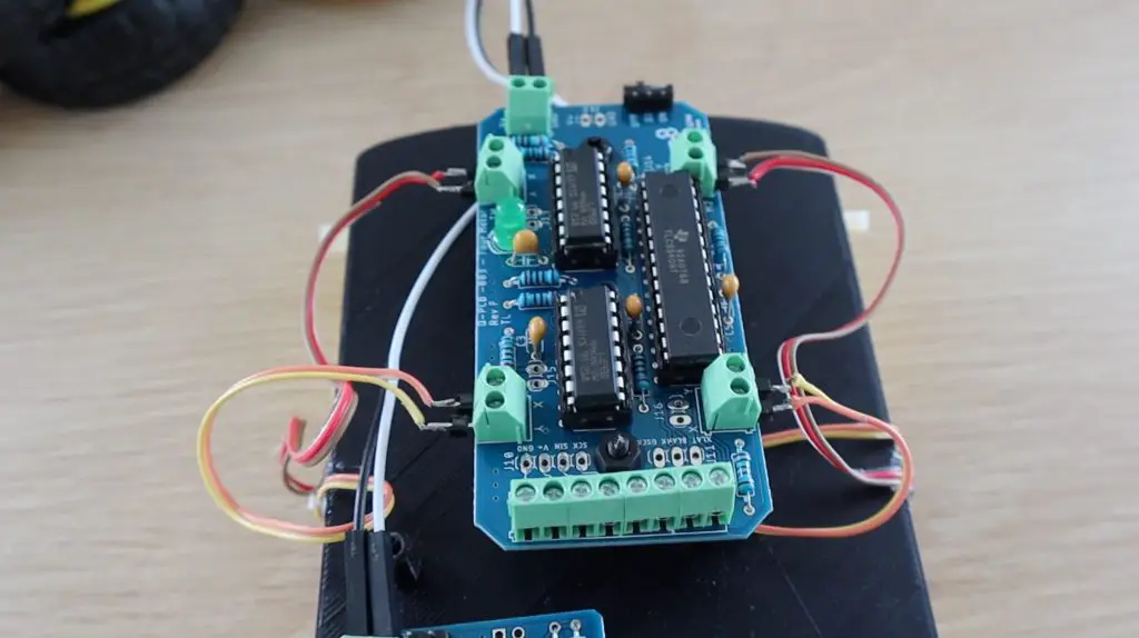
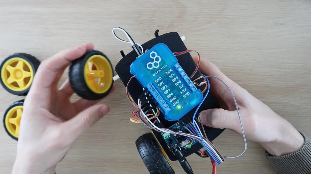
Then connect the motor driver to your builder base using the following pins:
- XLAT – GP1
- GSCLK – GP0
- BLANK – GP2
- SIN – GP3
- SCLK – GP4
- GND – GND
- 5V – 5V
I’m going to put the original wheels back on for the first part of the project and we’ll then look at expanding the functionality for the mecanum wheel movements.
Assembling The Joystick Controller
We’ve got our robot car built, now let’s assemble the joystick controller to control it with.
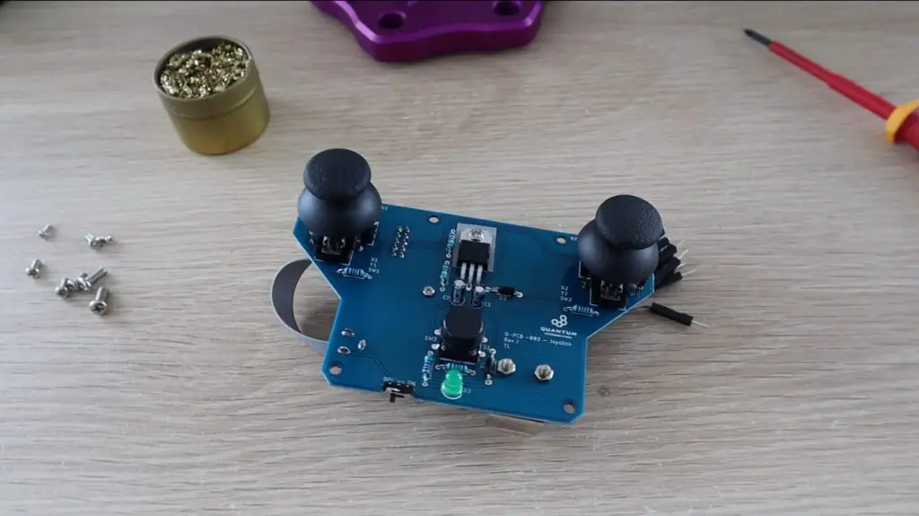
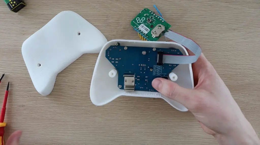
The joystick controller is the last PCB kit to assemble, and it features two two-axis joysticks with pushbuttons as well as a third pushbutton in the centre. It’s also got an onboard voltage regulator, so it can be powered directly using a 9V battery.
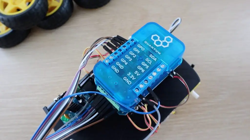
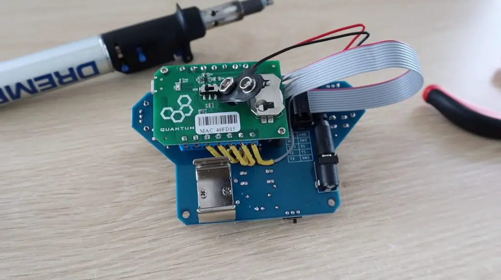
To add our builder base, we need to remove it from the plastic housing and screw it onto the brass standoffs provided on the joystick PCB.
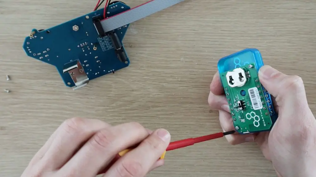
One thing to be aware of is that the battery holder is right up against the terminals on the builder base, and so is the joystick cover on the other side. So you need to use some flexible or 90-degree terminals to fit in alongside them.
Quantum provide a 3D printable housing for the joystick as well. I’ve printed that out in white PLA to put the PCB, builder base and battery into. The screws for this housing are also included with the joystick PCB kit.
The back cover is then held in place with two more screws. The controller can be switched on and off using the slide switch at the bottom and the green LED is illuminated when the controller is on.

Programming The Robot Car
Our robot car and joystick are now complete, so we can move on to programming them.
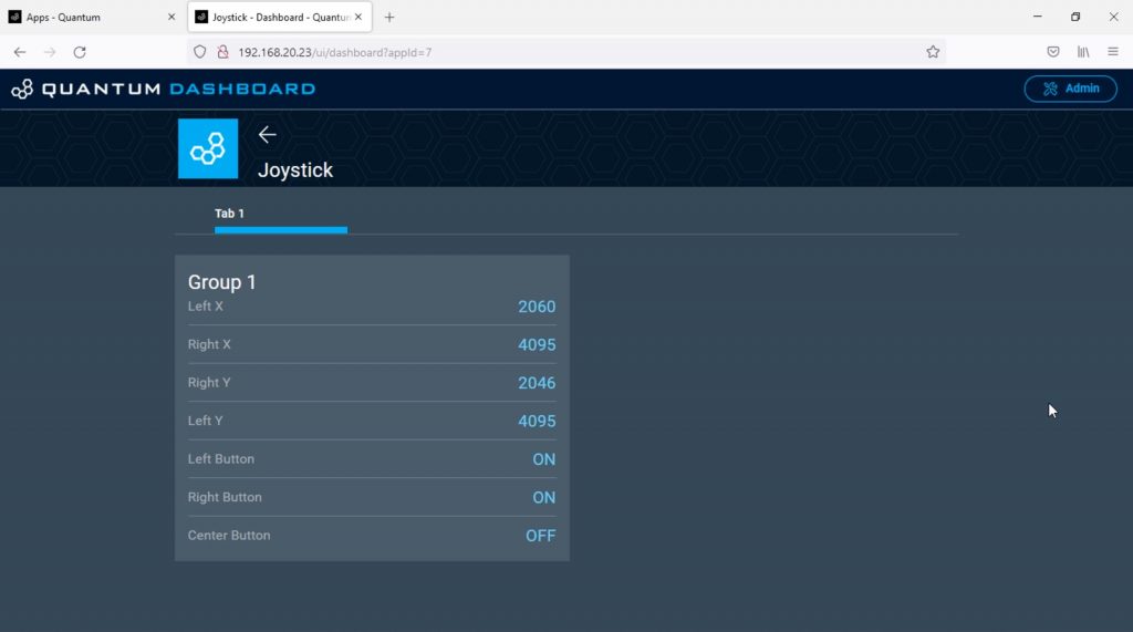
I’m going to start by testing that the system is receiving all of the inputs from the Joystick controller correctly. To do this I created a basic app that takes the three hardware objects, the two joysticks and the centre pushbutton, and displays their outputs on our app dashboard.
I also created the controller’s firmware and mapped the hardware objects to the pins that they are connected to on our controller’s builder base.
Quantum Integration have a similar project where they map the outputs to some analogue sliders if you’d like to try this as well.
With the app running, it looks like all of the axis are working correctly. We’re also able to see when each of the three buttons are pushed.
So now we can add our robot car to the app so that the joystick controller’s outputs drive the car.
I’m going to use Quantum Integrations base app for their robot car as a starting point, you can download the app and the firmware from their project page and this can then be imported into your server.
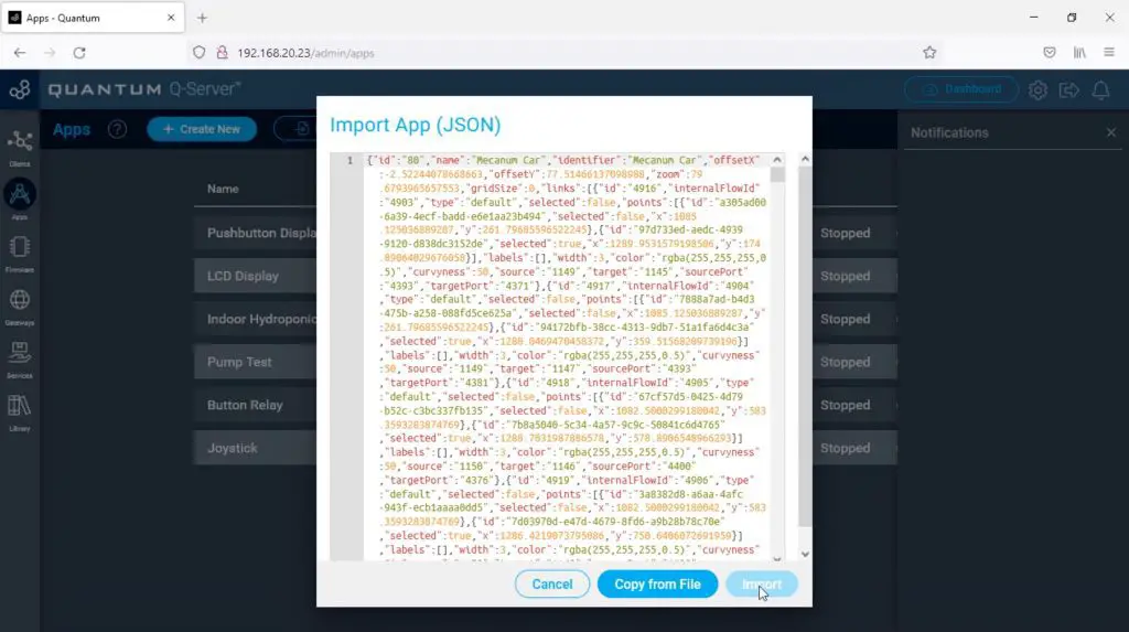
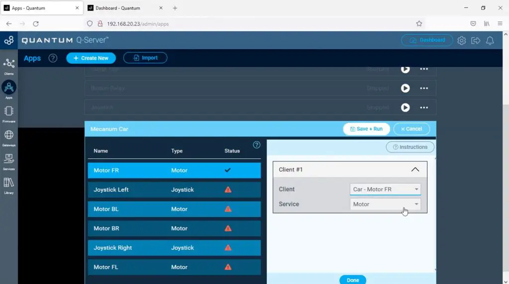
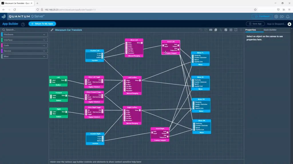
You should then see the following app.

This app takes the Y-axis of each of the two joysticks and maps the output to drive the left and right sets of wheels in pairs. So the left joystick drives the left two wheels and the right joystick drives the right two wheels.
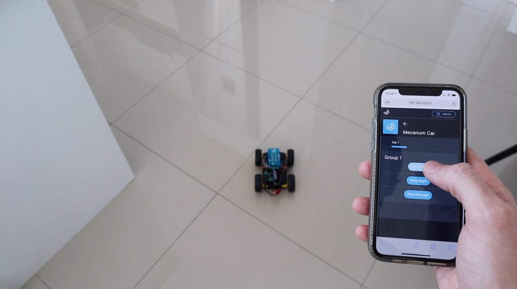
There are also three dashboard buttons, drive left, drive right and drive forward which enable the car to be controlled from the dashboard.
We’ll also need to upload the firmware to our robot car’s builder base, again this can be downloaded from the Quantum Integration project page.
We don’t need to worry about the joystick as we did this for the test we ran previously. We can then run the app and try out our robot car.
Lastly, we’ll need to assign the hardware objects that our app is going to use.
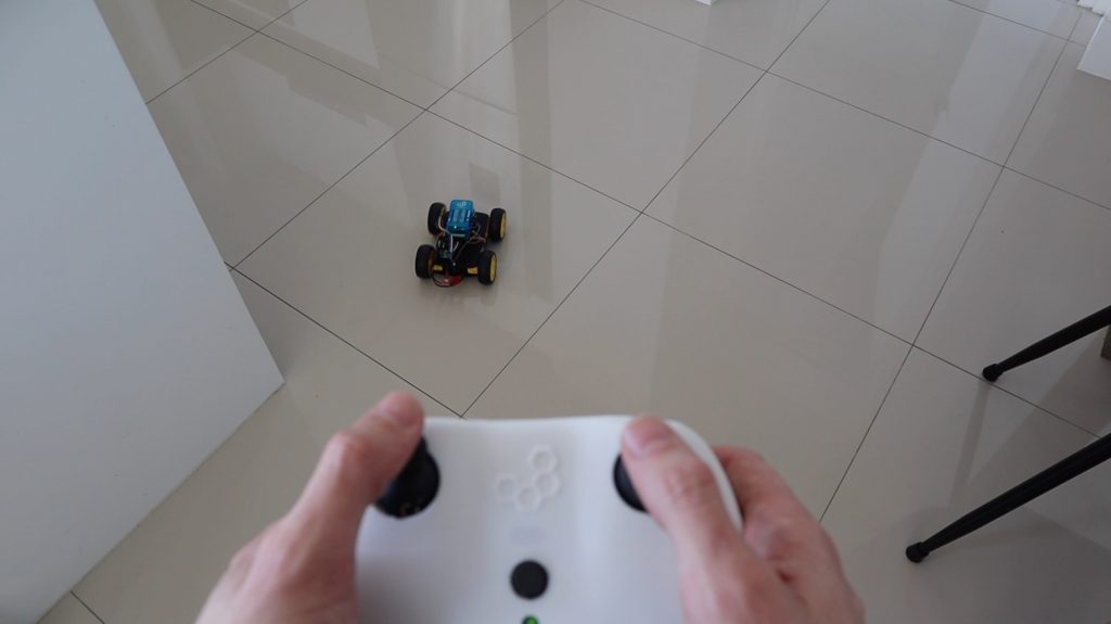
Controlling The Robot Car
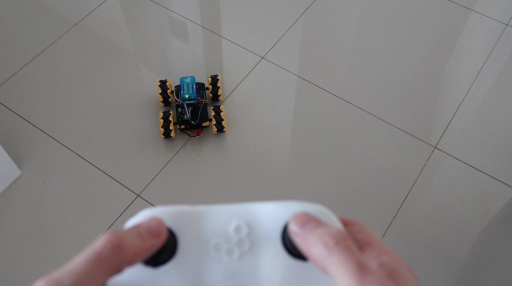
Now that our app is running, we can switch on the controller and the car’s power supply and try it out.
Pushing forward or backward on the left joystick drives the left wheels forward or backward and similarly for the right joystick and the right wheels.
To drive forward in a straight line, push both joysticks forward. To turn slightly push one forward at a time, and to turn on the spot push one forward and one backward.
We can also use the buttons on the dashboard, which we can access through our phone, to control the car rather than the joystick. These buttons don’t give you as much control as the joysticks do as they’re just on and off signals, not analogue signals, but you get the idea.
Adding The Mecanum Wheels & Omnidirectional Movements
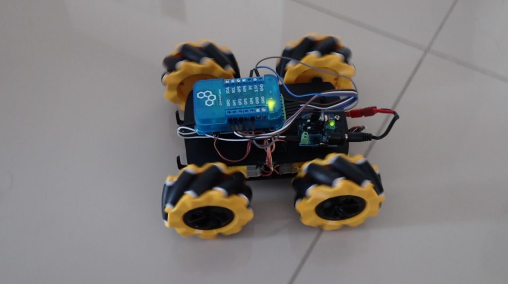
Now that we’ve got the basic robot car working, we’re going to look at adding the mecanum wheels. I’m going to replace the wheels on the robot car each with a mecanum wheel.
There are two different wheels, they are a mirror image of each other. They’re usually labelled with an LH or an RH on the inside of one of the hubs. You need to make sure that the wheels on the front and back are opposite hands so that they create a sideways reaction force when the rotate in opposite directions.
This is how I’ve installed them into my car.
You might need to use an adaptor to connect your wheels to your motor shafts. I used a 3D printable one by Pro Know.
Next we need to add some logic to the app to drive the wheels on one side in opposite directions when we want the car to move sideways. We could use the x-axis on one of our joysticks but I thought that it would be easier to use the joystick pushbuttons. So you push the left joystick to move left and the right joystick to move right.
I wrote a custom function block to produce a forward and backward signal when a button input is triggered. I connected the input to the left joystick button output and the forward and reverse outputs to our four motors. I then duplicated the function block for the right side as well.
Let’s save and run the app and see if it works. We don’t need to worry about the firmware as we’re using the same hardware that we used previously. Just make sure that the functions are mapped correctly and then run the app.
Our car is now able to move forward and backward, turn in either direction and move sideways without turning.
Let me know what you think of the mecanum wheels and this mecanum car in the comments section. Are you going to try to build your own mecanum car?