Raspberry Pi OS Bullseye has recently been released and with it comes a number of improvements, but most of them are under the hood. There aren’t that many visual differences, the most noticeable is probably the new default desktop background which is now a sunset over a dam or lake.
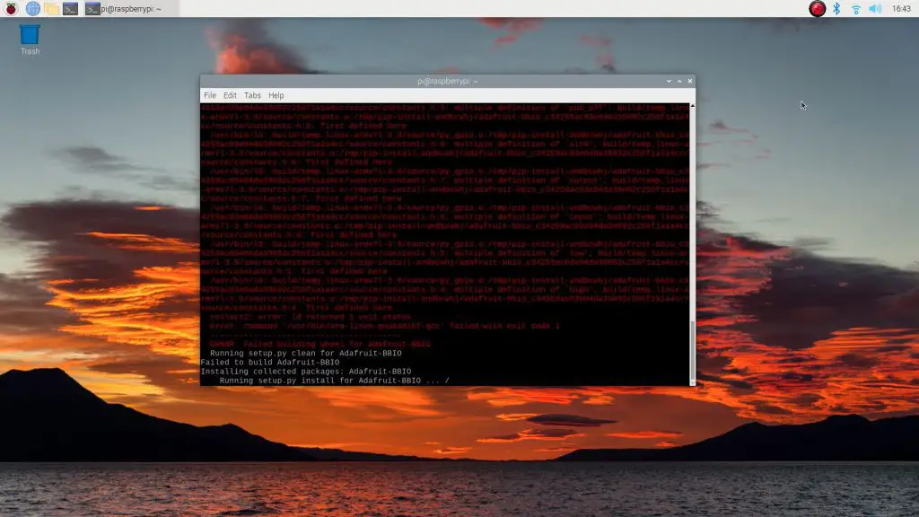
With this operating system upgrade, we’ve also got the usual bugs and software incompatibilities. These have caused my previous OLED stats display tutorial, that I used for my Raspberry Pi Desktop Case, to no longer work correctly. If you follow the previous tutorial, you’ll be presented with a host of errors.
So in this tutorial, I’ll take you through the installation and setup process to get the same 128×64 I2C OLED display running on Raspberry Pi OS Bullseye.
Here’s the video tutorial, read on for the written steps and commands.
What You Need For This Tutorial
- Raspberry Pi 4 – Buy Here
- Ice Tower – Buy Here
- Micro SD Card – Buy Here
- Raspberry Pi Power Supply – Buy Here
- I2C 128×64 OLED Display – Buy Here
- 4 Wire Female to Female Jumper Cable – Buy Here
Connecting Your OLED Stats Display To Your Raspberry Pi
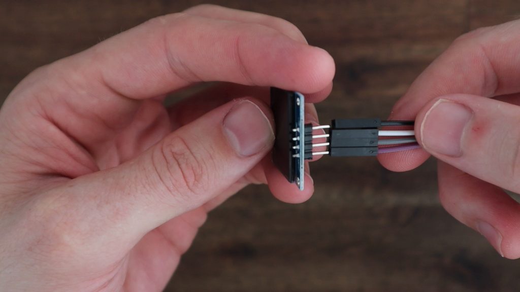
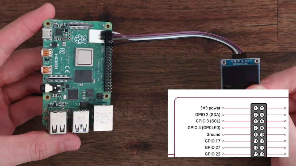
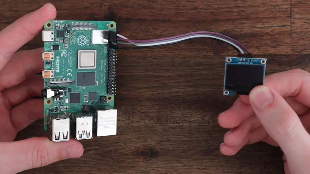
To start out, we’re going to go through the same process to connect the OLED stats display to our Raspberry Pi. To do this, you’ll need a 4 wire female to female jumper cable. The colours don’t matter, they’re just there to help you keep track of which wire goes to which terminal.
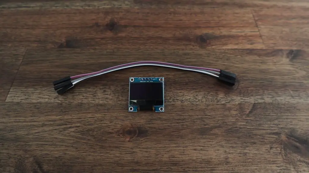
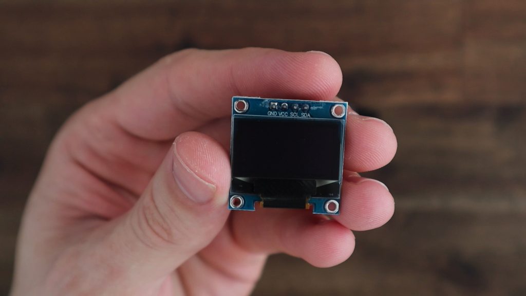
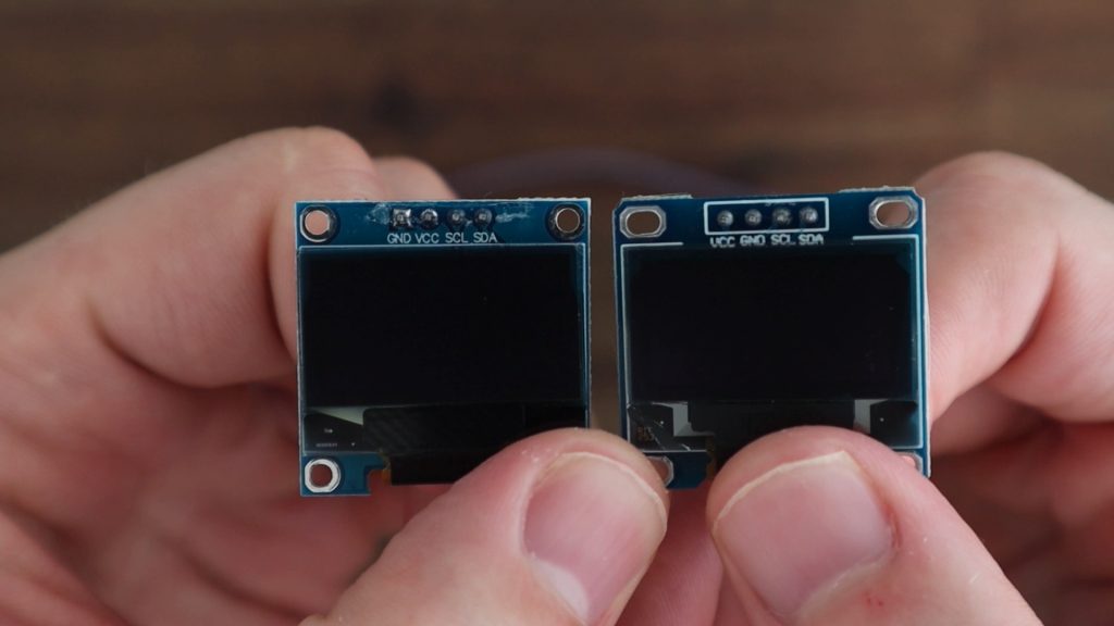
The OLED display’s terminals are labelled on the front, which seems to confuse a lot of people since the pins extend out the back of the display.
This is especially difficult to spot once the display has been installed into the case and the front area of the display is no longer visible. So make sure that you jot them down before installing the display into a case or holder.
The pin arrangement is most commonly GND, VCC, SCL and SDA. Don’t just copy this arrangement, make sure you check your own display as there are versions of these displays with the VCC and GND pins switched around. If you connect power to them incorrectly they’ll most likely be damaged and will no longer work, even if you correct the wiring afterwards.
Plug your ribbon cable into these four pins and then take note of which colour you’ve got connected to which pin. If you’re installing the display into your case before connecting it to your Raspberry Pi then it’s a good idea to write down which colour is connected to which pin so that you don’t forget.
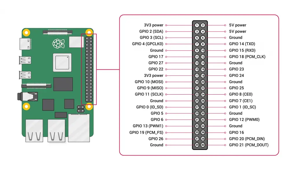
Next we can plug the other ends of the jumpers into the Raspberry Pi’s GPIO pins. The Pi’s GPIO pinout diagram can be found quite easily online and is available from the official website.
Make sure that your Pi is off and the power is disconnected before plugging or unplugging jumpers from the GPIO pins. You don’t want to short a connection or plug a lead into the incorrect pin by mistake and not have a chance to check your connections before powering it up.
You’ve got a few options for the GND and VCC jumpers. I usually plug the GND jumper into Pin 9 (you can use any pin labelled GND). And I plug the VCC jumper into Pin 1, which is a 3.3V power pin. These displays can operate on 3.3V or 5V inputs, so any power pins on the Pi’s GPIO header will work.

Next, we need to connect the communication jumpers SCL and SDA, which just get plugged into the corresponding GPIO pins. Plug SCL into Pin 5 and SDA into Pin 3. Don’t get confused between the GPIO numbers and the Pin numbers, ignore the GPIO numbers on the diagram and just go by the SDA and SCL labels and the corresponding pin numbers.
Check all of your connections again and you’re then ready to power your Pi up and get started with programming the display.
Programming The OLED Stats Display
Now that we’ve got the display connected, we can look at programming our Raspberry Pi to display the performance stats. I’m going to be doing this on a fresh install of Raspberry Pi OS Bullseye by using the Raspberry Pi Imager utility to flash the operating system image to a new microSD card.
Put the SD card into your Pi’s SD card slot and plug in your power adaptor. Once you’ve booted up your Pi, you should be on the Raspberry Pi OS desktop. It’s possible to do this installation on a headless Pi as well using the same steps.
Update Your Pi and Install The CircuitPython Library
Open up a new terminal window and start by making sure that your Pi’s software is all up to date by running the following commands:
sudo apt-get updatesudo apt-get full-upgradesudo rebootsudo apt-get install python3-pipsudo pip3 install --upgrade setuptools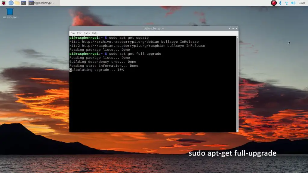
Next, we’re going to install the Adafruit CircuitPython library using the following commands:
cd ~sudo pip3 install --upgrade adafruit-python-shellwget https://raw.githubusercontent.com/adafruit/Raspberry-Pi-Installer-Scripts/master/raspi-blinka.pysudo python3 raspi-blinka.pyHit yes to any prompts which may come up and yes (Y) to reboot at the end.

Check That Your Display Can Be Seen
This previous installation script should also have enabled I2C communication, which is needed to communicate with the display. You can check that it is enabled and your Pi is able to see the connected display by entering the following command:
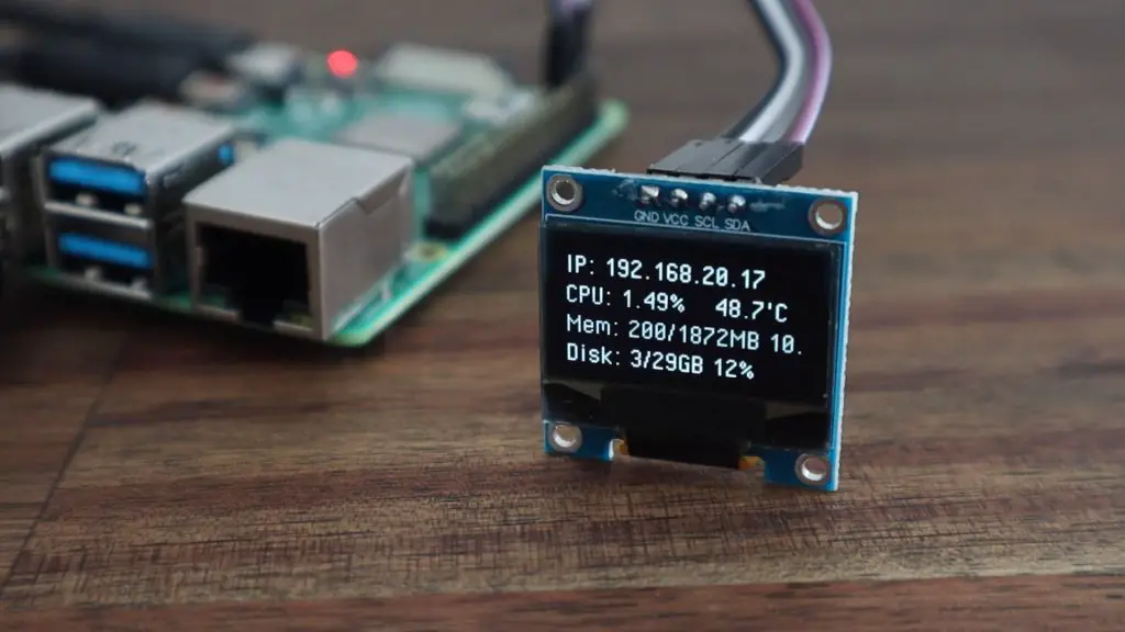
sudo i2cdetect -y 1You should then see a table, similar to the one shown below, which has a single set of characters in it (typically 3c for these displays). This code indicates the I2C address of your display.
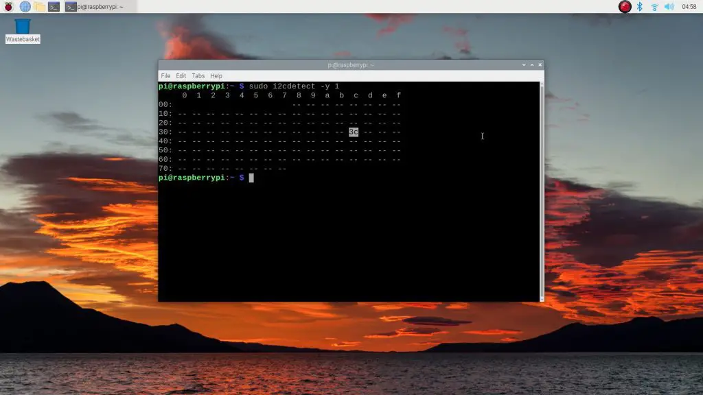
If it hasn’t shown up then either I2C communication isn’t turned on, which can be done through the configuration utility, or your wiring is not correct. If you get a table full of characters (all addresses shown) then you’ve probably made a wiring mistake as this happens if SDA is shorted to ground. Go back and re-check your connections to your Pi and display and re-check that you’ve got I2C communication enabled after a reboot.
To enable I2C communication, use the configuration utility by entering:
sudo raspi-configDon’t proceed with trying to get the script to work if you don’t get the correct response in this step. If your Raspberry Pi isn’t able to see the display that is connected to it then it won’t be able to communicate with it to get anything displayed.
Install The OLED Stats Display Script
Next, we need to install the CircuitPython libraries specific to the display. Start by entering the following commands:
sudo pip3 install adafruit-circuitpython-ssd1306sudo apt-get install python3-pilNow we just need to download the actual script. Rather than trying to edit it on the Pi, I’ve made it available on Github in its completed form, so you just need to run the following line to copy it to your Pi:
git clone https://github.com/mklements/OLED_Stats.git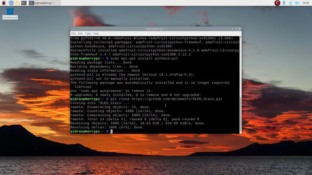
Navigate to the new cloned directly by entering:
cd OLED_StatsThen run the script by entering:
python3 stats.py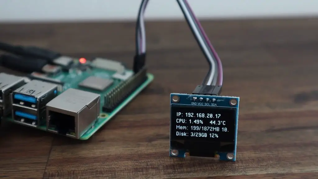
Automating The Script To Run On Start-up
Now we’ve got the display running, but it’ll stop as soon as we close the terminal window and we’d like it to run automatically on startup. We’re going to do this using crontab.
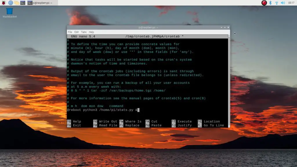
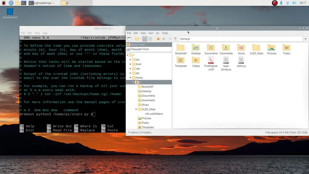
Open up crontab by entering the following command:
crontab –eIf this is the first time you’re opening crontab then you’ll be prompted to select an editor, select 1 and hit enter.
Add the following line to the end of the file to run the script:
@reboot python3 /home/pi/stats.py &Don’t forget the “&” at the end to tell the Pi to continue starting up and to run the script in the background.
We’ll also need to copy the stats.py script and font into the home directory. You can also just reference the correct path in the previous step, but I find that this is less reliable.
Make sure that you copy both the stats.py script and the PixelOperator font into the /home/pi directory.
cd OLED_Stats
cp PixelOperator.ttf ~/PixelOperator.ttf
cp stats.py ~/stats.py
cp fontawesome-webfont.ttf ~/fontawesome-webfont.ttf
If you do leave them in the downloaded directory, you’ll need to amend the crontab command to read:
@reboot cd /home/pi/OLED_Stats && python3 stats.py &Save the crontab file when you exit and then try rebooting your Pi to see if it is working correctly.
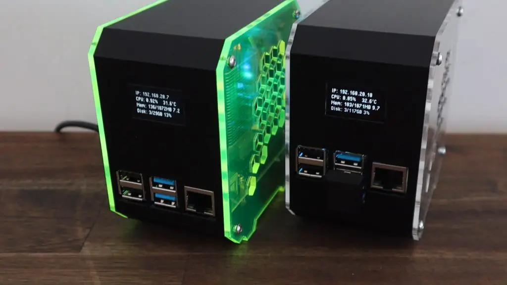
If you’ve followed the process correctly, you should now have a working OLED stats display that starts up automatically each time your Pi boots up. You can now go ahead and install it into your case if you haven’t done so already.
Finish Off Your Pi Desktop Case Build
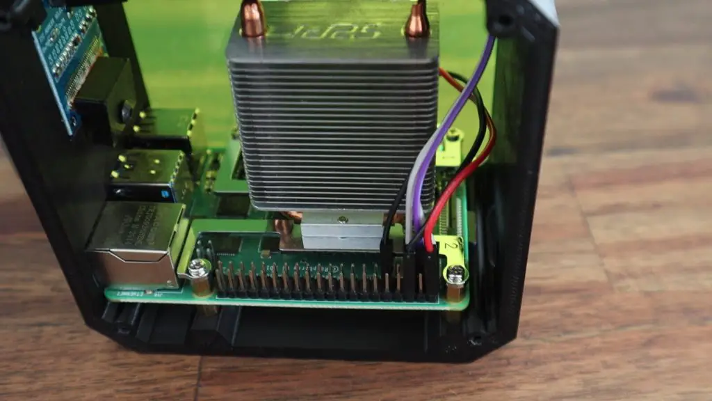
If you’re using an Ice Tower with your OLED stats display, plug the fan’s power cables into the 5V and GND GPIO pins next to the display’s connections as I’ve done.
Close up your case and your Raspberry Pi Desktop Case build is now complete.
Let me know how you find this tutorial in the comments section below. I’d love to hear your feedback and suggestions.
A couple of tiny typos in the commands listing. You missed a “g” at the front of the git command.
it clone https://github.com/mklements/OLED_Stats.git
and a capital letter in Python3 instead of lower case “p” in;
Python3 stats.py
Thank you Dazagrt, I’ve corrected them.
Hello, I am getting git clone https://github.com/mklements/OLED_Stats.git : Failed to connect to github.com port 443: Network is unreachable. I am using the command “git clone https://github.com/mklements/OLED_Stats.git“. anyone know what I am doing wrong ? Thank you
Ignore previous comment it worked after a reboot.
I am having issues to run the script
python3 /home/pi/OLED_Stats/stats.py
Traceback (most recent call last):
File “/home/pi/OLED_Stats/stats.py”, line 41, in
font = ImageFont.truetype(‘PixelOperator.ttf’, 16)
File “/usr/lib/python3/dist-packages/PIL/ImageFont.py”, line 852, in truetype
return freetype(font)
File “/usr/lib/python3/dist-packages/PIL/ImageFont.py”, line 849, in freetype
return FreeTypeFont(font, size, index, encoding, layout_engine)
File “/usr/lib/python3/dist-packages/PIL/ImageFont.py”, line 209, in __init__
self.font = core.getfont(
OSError: cannot open resource
If i try to run the script as follows it works
pi@raspberrypi:~ $ cd OLED_Stats/
pi@raspberrypi:~/OLED_Stats $ python3 stats.py
It looks like it isn’t seeing the font in the same directory (or isn’t looking in that directory for the font). Either use the default font or just put the script and font into the default directory.
Hi there. Take the file that you cut and pasted and paste it back into original location. Have a nice day
Invalid % CPU indication.
Hi Michael !
Great job but BLINKA just only works in Raspberry PI OS, how can I install it in other Distro (ubuntu mate) ?
I tried with your other videos but I could not get it
I tried to get it to work on Ubuntu but I read that Ubuntu doesn’t support the GPIO pins
You’ll need to use a library for your distro that allows you to run an OLED display. Each distribution has different package requirements, so you won’t find a single solution to all.
Michael, Thank you so much for this. As a complete newbie to Pi i spent several days trying to figure out what i was doing wrong. This updated guide now works perfectly. Only slight issue i had being a newbie, was trying to work out how to save the crontab file. you may want to add “press control X to save”.
Many thanks.
Thanks for the suggestion Paul. Happy to hear you’ve managed to get it working.
Hi, i read the article Mini Raspberry Pi Server With Built In UPS, and the script you supplied with UPS stats, does not work with this method of installation. I tried to make one my self, but i’m not so good at programming. Please can you make another script, working with this new method?
Thank you very much for the work you put into that.
Adding additional i2c.bus:
https://circuitpython.readthedocs.io/projects/extended_bus/en/latest/ #install this lib as described
Add the following lines to your OLED_Stats/stats.py:
from adafruit_extended_bus import ExtendedI2C as I2C
I2C = I2C(7) # This is the additional bus you created in boot.txt like you find in ls /dev/i2c* so i2c-2 is 2 and so on. Hope this will help others 😉
Help please!
I’m trying this on a R-Pi 3B but the display is showing almost all pixels On and some Off.
On the top of the display it shows some “Disk” stuff.
I’m using a 128×64 display and Raspberry Pi OS.
All the wiring is correct.
I even tried another display to check if the previous was faulty.
Hello.
It looks like your display uses different driver chip. I had the same issue.
Here is link for library by Adafruit for the other common driver chip.
https://github.com/adafruit/Adafruit_CircuitPython_DisplayIO_SH1106
getting this message when i try to run the script:
pi@raspberrypi:~/OLED_Stats $ sudo python3 stats.py
Traceback (most recent call last):
File “/home/pi/OLED_Stats/stats.py”, line 6, in
import board
ModuleNotFoundError: No module named ‘board’
If you leave the contents in the original folder and want to run the script on boot, nano into stats.py then locate
“font = ImageFont.truetype(‘PixelOperator.ttf’, 16)”
and change it to
“font = ImageFont.truetype(‘/home/pi/OLED_Stats/PixelOperator.ttf’, 16)”
or the full path to the folder you have it in. Save and then try again. Should fix you up
Sorry I do not understand what you mean by this. Wording is too complicated, how do you locate the font or full paths and save them?
Hello,
I was able to get this working with the new version of raspbarian bullseye. I added the py code that I used here. I also did a full library upgrade as well.
https://street-tek.dev/stats.py
Thank you, much appreciated.
I was currently working on this and my code was very similar to your code but I forgot to import a library and was searching forever for the error.
Hi Ed,
can you re-link or email a copy of the stats.py? I am attempting to build the diy rpi 4 with bullseye and could really us it.
thanks.
hello kind sir,
would you be willing to do the bullseye OS update for the UPS build of yours?
Thank you!
Hi Ed Street,
I’m happy to hear you’ve managed to get the UPS version working as well. Are you happy with me putting the code you’ve linked to into a GitHub repository and linking to it on this page and the UPS page?
Hello, how to add a RX/TX show trafic in the display?
You would need to fetch that information from another application and you can then add a line to the display from within this script.
got it, im buy a new display and see the controler is SH1106, can you migrate the script to display in this model?
I got it somewhat working. When I run the script it works, but Im having trouble with the final couple steps to make it work on boot and in the background. After I run the script, its just….. running. Im not sent back to # to enter any more commands. You dont mention anything about this, so I hit Ctrl+C and get back to #.
I then enter the command crontab –e, but then I get:
“–e: No such file or directory”
Is this the correct command, because it doesnt seem to work?
If you’re running it in the Lite version (no desktop) then you need to add an & at the end of the command otherwise it’ll just keep “running” as you’ve said and you won’t be able to do anything else until it is stopped.
The issue with crontab is most likely related to you working in the wrong directory. If you’ve navigated to the directory containing the script then you need to return to the home directory to modify the crontab file.
try sudo crontab -e
Hello, I make this project, but I want to see same info like disk but for my external drive (/dev/sda1). Can you tell me script? Thank you!
I haven’t tried displaying information from another disk. The script commands came from this link, so you could try asking there – https://unix.stackexchange.com/questions/119126/command-to-display-memory-usage-disk-usage-and-cpu-load
Hello Michael,
I have no RPi and Python experience. With your description it was no problem to put the status display into operation.
Thank you very much.
same questions and comments
1.) After a shutdown the content on the OLED remains. Is there any way to clear the content of the OLED without turning off the RPi?
2.) What does board.D4 need to be defined for if the reset is not used at all. (To satisfy the adafriut lib?).
3.) Is there a possibility to rotate the screen content? I didn’t find it in the lib of Adafruit.
4.) Some time ago I had bought OLEDs SSD1306 (multicolor) from China. My first line is yellow and the next 3 lines are white. Is the font color configurable?
5.) I want to use the RPi in continuous operation. The operating time for OLEDs is limited. What is your experience? I have an additional PIR – sensor planned. Even without Python experience I will try to include the code.
Hi, if you run ‘df -h’ (without the quotes) in the terminal you’ll see in the final column (mounted on) the mount point of your external drive.
You just need to alter this line in the script:
“df -h | awk ‘$NF==\”/\”{printf \”Disk: %d/%dGB %s\”, $3,$2,$5}'”
In my case I swapped out the / in “/\” to “/mnt/Media\” to display its usage, as that’s what I have mounted to /dev/sda1
Thanks a lot! It took me some trial and error to figure out what you meant. Basically after doing the df -h command I looked at the path that the dev/sda1 is mounted on. like for you it was just /mnt/Media and mine was like /srv/dev-disk-by-uuid-####A-#AA##-##AA… (where # means specific numbers and A means specific letters.)
This script configures your
Raspberry Pi and installs Blinka
RASPBERRY_PI_ZERO detected.
Updating System Packages
Blinka Hit:1 http://raspbian.raspberrypi.org/raspbian bullseye InRelease
Blinka Hit:2 http://archive.raspberrypi.org/debian bullseye InRelease
Blinka Reading package lists…
Upgrading packages…
Blinka E: Broken packages
Blinka Reading package lists…
Blinka Building dependency tree…
Blinka Reading state information…
Blinka Calculating upgrade…
Blinka Some packages could not be installed. This may mean that you have
Blinka requested an impossible situation or if you are using the unstable
Blinka distribution that some required packages have not yet been created
Blinka or been moved out of Incoming.
Blinka The following information may help to resolve the situation:
Blinka
Blinka The following packages have unmet dependencies:
Blinka vlc-bin : Depends: libvlc-bin (= 3.0.16-1+rpi1+rpt1) but 3.0.16-1+rpi1+rpt2 is to be installed
Blinka vlc-plugin-skins2 : Depends: vlc-plugin-qt (= 3.0.16-1+rpi1+rpt2) but 3.0.16-1+rpi1+rpt1 is to be installed
Blinka Exiting due to error: Apt failed to install software!
pi@raspberrypi:~ $
?????
Hello Michael, I’m running Ubuntu server 64 bit on my Pi and I’m trying to get the OLED to work. Up until now no success. I can seed the the display is connected and I have the address, but then that’s it. the rest of instruction won’t work. I you could help that we be nice.
Hello I’ve finally manage to make it work with the following setup:
– Raspberry Pi 4 (8GB)
– Ubuntu Server 21.10 (64-bit server OS for arm64 architectures)
– Mini-tower case with SSD (NVMe M.2)
– OLED Display
Thanks for your tutorial. it guided me in the right direction on many instances.
K.R.
It would be nice to share how you did …
Hey I’ve created a gist on Github.
https://gist.github.com/Nguimjeu/6e86eff080beb3ed1589c7bd3d3b8e7f
Hope this helps. Credit are of course going to the Author of this article
It is working but on the line with cpu and temp it is displaying the cpu info twice and interfering with the temp so it just looks jumbled, it reads: cpu 1.21cpujumbled mess
So I figures out there is an error on the code somewhere. I tool out the IP address and moved cpu line up in its location. Now I can see cpu temp. The CPU line reads : cpu 1.62 cpu 20%. The example you show here doesnt look that way. So the part that says cpu 20% was running into the cpu temp. So you know what in the code need to be changes to remove the cpu 20% part? I would like to have the IP address displayed
Hi Aaron,
The code that I’ve got on github is the repository that I use to install this script on all of my Pi’s and I’ve never seen this issue come up. Could you share some details on what Pi you’re running it on and what operating system you’re running? Unless a recent OS update has caused a change to the data that this script pulls from, there shouldn’t be any difference.
I am running an OS called raspex but it is debian 11 based on my raspberry pi 4 4gb.
Yeah, that’s likely why you’ve got a different layout. It’s probably reporting the stat back in a slightly different format to Raspberry Pi OS and that’s why its overwriting the same line on the display. You’ll need to see what exactly is being stored in each variable when putting together the display output and then work out how that fits best onto the display.
Is there information about how to display bitcoin price on display when running Umbrel node by chance?
As far as I know, Umbrel runs on a version of Debian that they’ve modified to run their software on. You could probably get the display working on it, but you’d need to install a lot of libraries and dependencies that likely aren’t there by default. You’re probably better off getting a mini desktop display for the Pi and displaying the Umbrel dashboard on it.
My OLED display is hard mounted to a NAS unit and it is currently displaying information upside-down. How or where can I make a change in the software to invert my display?
don´t work :/
pi@octopi:~ $ cd OLED_Stats
pi@octopi:~/OLED_Stats $ python3 stats.py
Traceback (most recent call last):
File “stats.py”, line 11, in
import adafruit_ssd1306
File “/home/pi/.local/lib/python3.7/site-packages/adafruit_ssd1306.py”, line 17, in
from adafruit_bus_device import i2c_device, spi_device
File “/home/pi/.local/lib/python3.7/site-packages/adafruit_bus_device/i2c_device.py”, line 26, in
class I2CDevice:
File “/home/pi/.local/lib/python3.7/site-packages/adafruit_bus_device/i2c_device.py”, line 65, in I2CDevice
self, buf: WriteableBuffer, *, start: int = 0, end: Optional[int] = None
NameError: name ‘WriteableBuffer’ is not defined
pi@octopi:~/OLED_Stats $ cd ..
This tutorial is written for Raspberry Pi OS Bullseye – it hasn’t been tested on other operating systems (like Octopi). These might be missing libraries or dependencies that this script relies on in order to run.
Hey Michael,
Thaks for this great writeup – it worked right away on my first Pi 4b, next one, everything installed fine, the screen teset shows blank and 3c in 1 field as expected. Running your script produces an error:
Traceback (most recent call last):
File “stats.py”, line 11, in
import adafruit_ssd1306
File “/home/pi/.local/lib/python3.7/site-packages/adafruit_ssd1306.py”, line 17, in
from adafruit_bus_device import i2c_device, spi_device
File “/home/pi/.local/lib/python3.7/site-packages/adafruit_bus_device/i2c_device.py”, line 26, in
class I2CDevice:
File “/home/pi/.local/lib/python3.7/site-packages/adafruit_bus_device/i2c_device.py”, line 65, in I2CDevice
self, buf: WriteableBuffer, *, start: int = 0, end: Optional[int] = None
NameError: name ‘WriteableBuffer’ is not defined
Do you have any clues for me?
It seems like you might have some sort of communication issue. Id try reconnecting the display and re-run through the software setup to make sure all libraries are installed and enabled.
So i actually loosened my screws up a bit, ran the whole install again, and bob is your uncle 🙂 im running it on the latest Octopi, for reference – only crontab is acting up in this setup, i do have to have a terminal window open for each octopi i have to have the screens live updated – any ideas to a workaround would be much appreciated 🙂
That’s great to hear!
I have manged to get everything up and running but I notice the the CPU usage does not get above 9.99%.
I have looked through your pictures in this page and yours does not seem to go very high either, mostly about 1-5%
I have times when I am using 90% of CPU. Is there not enough digits in the coding to allow for higher amounts of CPU usage ?
Hi Taurus548,
The metric displayed is the CPU load, not % utilisation. It’s a bit confusing because Adafruit added the % sign after it, which is not actually correct and can/should be removed. I’d suggest reading up on cpu load vs utilisation – https://bit.ly/3sKyGJC
Thanks Michael! The article https://bit.ly/3sKyGJC explains it nicely. So the % sign is what is wrong.
This is an awesome rundown!
However, my display is constantly flashing. Is there a reason this is occuring and something i can fix?
Thanks!
Is it flashing consistently at a specific frequency or just intermittently. I’d say it’s most likely a loose connection or faulty wire if it’s intermittent.
Hi
Mine is also flashing at a constant rate, approximately every second.
Thanks Michael. Turns out it was a faulty display so I got a replacement
Hi Michael! With RPiOS 64-bit officially released now, I am trying this on my own Pi4!
However, I have hit a snag….the default Pi I2C bus on my Pi is set up for my power button to use, so I have a custom second I2C bus set up on my Pi that my screen is connected to (Bus 4)
How do I go about changing your stats.py script to specify using a different I2C bus (in my case, Bus 4) other than the default bus (Bus 1)? 🙂
Thanks so much for the awesome videos/articles and all the hard work!
Also stuck here! I have a PiJuice connected that won’t seem to allow me to have another device on the bus, despite different addresses! Have configured the i2c display on bus 2 but can’t seem to make any headway on readdressing for a different bus!
Hey Rally and Sven!
In case you didn’t get it working, I found it after a day of searching:
https://github.com/adafruit/Adafruit_Python_Extended_Bus
use this library instead of board to set up the i2c connection on an alternate bus.
Example:
from adafruit_extended_bus import ExtendedI2C as I2C
…
# Use for I2C.
i2c = I2C(4) # creates an i2c connection on bus 4
oled = adafruit_ssd1306.SSD1306_I2C(WIDTH, HEIGHT, i2c, addr=0x3C, reset=oled_reset)
Hope you get yours working too!
Great explanation, thank you!
How can I prevent burn in the OLED screen?
(screen off on certain time, at night for example)
The CPU will be always 1.00%
But when I do: top -n 1 -b | awk ‘/^%Cpu/{print $2}’ the percentage of the CPU is 15-20%
How can I fix this?
If you’re worried about burn-in because you leave the Pi on for long periods of time then you could implement a timer in the code that only displays the text during the day (as you’ve suggested). These displays are also relatively cheap, $5-8, so you could just replace them every 6-12 months if this becomes an issue.
I’m not really sure what you mean with regards to the CPU percentage?
He seguido el tutorial y me funciona bien, no obstante después instalé una cámara raspi y, si bien la cámara funciona, la pantalla no funciona cuando apago y enciendo el raspberrypi.
I have followed the tutorial and it works fine for me, however after installing a raspi camera and while the camera works, the screen does not work when I turn the raspberrypi off and on.
(traducción del español con Google)
Hey Michael,
Have got the script working, awesome, thankyou!
However, i’ve added a hat that will not allow a second device on the default i2c bus. I’ve used dtoverlay to move my display to bus 3, using different pins, and they are recognised in i2cdetect.
I’m hoping you could tell me how to adjust your code to import the software bus to use bus 3!
Cheers
Hi Michael, great job and great design i love it! I tried it with a RP3 and everything works fine(Rp4 nowhere available) but on RP3 the network adaptor is on the other site then a RP4. Do you have also a design for the RP3 or something i can adapt to a RP3? Thank you
So, this is fantastic! Up and running in 5 minutes.
Question (and I’m surprised this wasn’t asked) how do we go about converting temp to Fahrenheit here?
I know the formula is fahrenheit = celsius * 1.8 + 32
But not sure where this would be placed in the actual code.
cmd = “vcgencmd measure_temp |cut -f 2 -d ‘='”
temp = subprocess.check_output(cmd, shell = True )
My only python experience like this was reading sensors like so:
reading = sensor_temp.read_u16() * conversion_factor
temperature = 27 – (reading – 0.706)/0.001721
temperature = temperature * 9 / 5 + 42 # Should be 9 / 5 + 32
print(temperature)
Any ideas?
This one shows an offset in the math due to a bum sensor.
Hi Rickles,
This is something that a couple of people have looked at before, I can’t recall if it was on one of my other blog posts or in the comments of the Youtube video. What you’ve suggested is technically correct but you’d need to get the script to first convert the temperature into an actual number. At the moment the reported temperature value is just a text field, so you can’t apply the above conversion maths to it directly.
Thanks, I’ll dig into it!
For those that commented on CPU shoeing percentage when it’s really Load Average, yeah – it bugged the hell out of me too 🙂
A quick fix in stats.py is to change line 63 to read like this::
draw.text((0, 16), str(CPU,’utf-8′) + “LA”, font=font, fill=255)
All I did was remove the “%” and replace it with “LA” for “Load Average”. Cheesy, but it turned off the OCD! 🙂
Why wasn’t it updated on git? Iit’s like 4 months since it was pointed out
Are you asking me? I *just* set this up the other day. Noticed it in the comments so I followed up.
It’s in the latest commit.
I thought I had changed this last year already but I must have uploaded the previous revision of the code.
That was aimed at the last poster (Tomek). I fixed it on my own ?
Hi friend, congratulations for the post. really enjoyed.
I have 4 lte 4g modems and I also have internet and local network in Ethernets Interfaces.
how do i show the data bandwidth consumed by these devices?
would you have any suggestions?
I don’t know which commands I should use.
Sorry for the translation, I only speak Portuguese and I use the translator to write.
thanks.
Hi Seu João,
You would need to find a python script, either from the manufacturer or some open-source repository, that gives you access to that data. You could then easily merge that with this script and adjust the displayed information to include all of the contents.
Hi Michael,
I just finished building your stats Raspberry Pi case with stats display and SSD, which I purchased off you via etsy recently. A great kit!
One thing I realised after the build, was that the OLED display is set up for a standard OS install. I’ve set up this Pi as a Home Assistant host, which of course uses its own OS. So the display will remain dark for now. (can’t install the python features your instructions refer to)
Any links or advice on an addin to set up the display in HA? Not the end of the world if it isn’t possible.
Regards,
Paul
Paul –
did you every sort this out?
Hi Michael !
Great job but
pip3 install adafruit-circuitpython-ssd1306
should be
sudo pip3 install adafruit-circuitpython-ssd1306
if not, jobs at crontab will not run
regards
Norbert
I’m using the most current version of retropie, and I am able to get the stats display to show up but am unsuccessful at getting them to start up at boot. Is there anything else I could try ? or that I may be doing incorrectly .
also after I enter python3 stats.py the Pi@retropi disappears all the text is white and commands wont work
instrad of
pip3 install adafruit-circuitpython-ssd1306
try this
sudo pip3 install adafruit-circuitpython-ssd1306
stats at boot works now for me
Hi Michael! The case is amazing, thanks! (still would like to kick customs in the shin)
I got the OLED display working (sort of). It doesn’t appear to be updating. The stats never change. No errors. Any idea?
I ran through your instructions this evening and ran into one snag. It doesnt seem that the git function is installed on a fresh build. I am running the x64 lite version of Raspbian. This was resolved with a simple
sudo apt-get install git
Dont know if anyone else is having that issue.
Are you sure git isn’t just left out of the ‘lite’ build of Raspbian? I don’t recall having to install it with the normal full version? (I am running 64-bit Raspberry Pi OS with the Twister OS mod)
how do you convert the temp from C to F degrees?
amazing post
it’s rare to see a guide where i can just follow allong without any issues
Michael,
I love this tutorial. I had no major issue getting it running. Like other users I couldn’t (at first work out the CPU information and was expecting this to be shown as a %.
I played about with using other fonts and font sizes successfully with the intent of adding an additional line for Network (accumulative data use) which I would like to have shown for an ADSB monitoring project using a PiAware image. This would be mounted remotely at a “non technical” persons house whereby this information would be great to be shown on the display.
I managed to cobble together the following.. but it seems it does not run under python I believe due to the additional awk statements and formatting.
#Shell script (section)
…
cmd = “ip -s -h link show eth0 | awk ‘/RX:/{getline; rx=$1} /TX:/{getline; tx=$1; printf “%s / %s\n”, rx, tx}'”
Net = subprocess.check_output(cmd, shell = True )
#Pi Stats Display (section)
….
draw.text((0, 48), “RX/TX: ” + str(Net,’utf-8’), font=font, fill=255)
Would anyone have any ideas as to whether it is possible to run such a command within python? And if so how would it be done?
To help those who are using a SH1106 Oled Display on their Raspberry Pi, my brother has created a revised ‘stats.py’ python script that is a direct replacement to the Michael Klements original ‘Stats.py’ script. Thanks to Michael for the original version.
You can download the new script from the following URL
https://github.com/andrewcliffoutlook/OLED_Stats_SH1106
Should have read the comments before…
I also made a version for SH1106 using luma.oled for the ‘monitor.py’
https://github.com/Hondo123/OLED_Stats_SH1106
Any body wanting to know the format of the awk comand that refers to the disc reporting … just a FYI
my example is
cmd = “df -h | awk ‘$NF==\”/srv/dev-disk-by-uuid-E096-7FA2\”{printf \”1> %s %s Used\”,$2,$5,$4,$5}'”
the end statement $2,$5,$4,$5
this refers to the columns of the df -u command
$2 = Size of the drive
$3 = Used
$4 = Avail
$5 = Use%
the order you place them in is the order you will display the info
usage is %s — the ‘s’ will read and display both the drive size number nd capacity in Gig , MB , or T
if you use %d — this will just read and display the number value of the drive , this will allow you to set your own extension
if you have built a NAS server with OMV with multiple drives, there is a way to setup your stats.py to display pages to show the rest of the drives and scroll through them every 5 or so seconds on repeat. If anybody is interested , pop a comment and ill upload a sample of my stats.py
FYI the new RaspberryPi OS “Bookworm” breaks this tutorial as python packages like pip are now recommended to run in their own virtual environment.
Thanks for the project. I purchased the 52Pi case put everything in the case, installed the software following your instructions and has everything working. Glued the screen into place and then I closed up the case with the supplied sides.
Now when I run the script, I get the following:
Traceback (most recent call last):
File “/home/scott/stats.py”, line 73, in
oled.show()
File “/usr/local/lib/python3.9/dist-packages/adafruit_ssd1306.py”, line 219, in show
self.write_framebuf()
File “/usr/local/lib/python3.9/dist-packages/adafruit_ssd1306.py”, line 287, in write_framebuf
self.i2c_device.write(self.buffer)
File “/usr/local/lib/python3.9/dist-packages/adafruit_bus_device/i2c_device.py”, line 100, in write
self.i2c.writeto(self.device_address, buf, start=start, end=end)
File “/home/scott/.local/lib/python3.9/site-packages/busio.py”, line 206, in writeto
return self._i2c.writeto(address, memoryview(buffer)[start:end], stop=True)
File “/home/scott/.local/lib/python3.9/site-packages/adafruit_blinka/microcontroller/generic_linux/i2c.py”, line 60, in writeto
self._i2c_bus.write_bytes(address, buffer[start:end])
File “/usr/local/lib/python3.9/dist-packages/Adafruit_PureIO/smbus.py”, line 303, in write_bytes
self._device.write(buf)
TimeoutError: [Errno 110] Connection timed out
Any suggestions?
hello michael, good tutorials for beginners like me.i had install fresh new raspbian bullseye lite 64 and followed your tutorial and managed to get the lcd working.i only can managed to set to auto start after reboot.and i found some error on this line:-
rpi4@pi4:~/OLED_Stats $ cp fontawesome-webfont.ttf ~/fontawesome-webfont.ttf
cp: cannot stat ‘fontawesome-webfont.ttf’: No such file or directory
any help on why the script does not start on boot?
avg42slot review If you are a person who likes playing games and doing online pg slot or is looking for a new way to have fun with online slot games. Recommended to try playing AVG42slot.
Hello Michael. I have a slightly longer display at .91 inches and is 128×38. If I change the parameters in stats.py should everything work and fit the screen dimensions? What do I need to do to make sure this works properly? Thanks in advance!
Would really like to see a refresh to the OLED Display for Bookworm OS…
ดูหนังออนไลน์ หนังใหม่ชนโรง ดูหนังhd หนังมาสเตอร์ พากย์ไทย ซับไทย ดูซีรี่ย์เกาหลี ซีรี่ย์ฝรั่ง Netflix ดูบอล ดูฟรีไม่เสียค่าใช้จ่าย ไม่ต้องสมัครสมาชิก ได้ที่ ดูหนัง.live
I successfully installed and had this running since 2021, but due to Bookworm and virtual environments etc I am struggling to get my head around installing.
Can anyone assist?
Thank you
Easy peasy nice and easy with this!
Any updates to this project for Bookworm?
Hi,
Thank you for your tutorial. It helped me to wake up my mini oled screen. I´m doing a project (rasptank) where I use an mini oled screen connected to an Robot HAT 3.0. Everything works and displayed correctly after use command “python3 stats.py” but when I restart the raspberry, it does the autorun but won´t display correctly anymore, it is like refreshing or somehting, you can read some display text but not all. If i use the command “python3 stats.py” everything displays correctly again.
Any tip?
Greetings
They’re all definitely some great sites!
ขอบคุณสำหรับบทความดี ๆ ครับ เนื้อหาน่าสนใจมาก
ถ้าใครสนใจเกมออนไลน์หรือแนวความบันเทิงแบบครบวงจร ลองดูที่นี่ก็ได้ครับ
เกมออนไลน์ครบวงจร รวมทั้งเทคนิค บทความ และรีวิวเว็บน่าเล่นไว้ครบ
อยากได้เงินจริงจากการเล่นเกมแต่ไม่อยากลงทุน?
เรามีข้อมูลเด็ดๆ มาฝาก! เจาะลึกเทคนิคและประเภท “เกมได้เงินจริงไม่ต้องลงทุน” ที่คุณอาจไม่เคยรู้มาก่อน! ใครว่าเล่นเกมแล้วเสียเวลาอย่างเดียว ลองดูโพสต์นี้แล้วคุณจะเปลี่ยนความคิด!
คอมเมนต์ด่วน! อยากรู้ว่าเกมไหนบ้างที่เล่นฟรีแล้วได้เงินจริง?
ขอบคุณสำหรับบทความนะคะ ช่วยให้ตัดสินใจเลือก กรอบไมครอน ได้ง่ายขึ้นมากเลยค่ะ ล่าสุดเพิ่งสั่งทำกรอบพระที่ออกแบบเองกับช่างฝีมือ ดีไซน์เข้ากับองค์พระพอดีเลยค่ะ
How to it run on Raspberry pi zero 2w
Right here is the right site for anyone who wishes to understand this topic. You realize so much its almost hard to argue with you (not that I really will need to…HaHa). You definitely put a fresh spin on a topic that has been written about for decades. Wonderful stuff, just excellent!