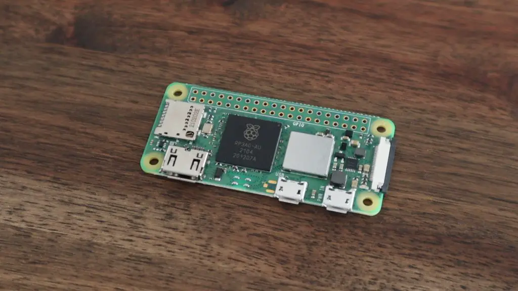
In this project, we’re going to be making a case for the Raspberry Pi Zero 2 W. This is a new and more powerful version of the original Pi Zero W, and has a quad-core 64-bit Broadcom BCM 2710 A1 chip. The CPU is similar to the original Pi 3, but with a few tweaks made specifically for the Pi Zero 2 W.
This new, more powerful board is a significant improvement over the original Pi Zero, but it also uses more power and produces more heat. So we’re going to design a case which uses a 40mm fan to provide some additional cooling to the CPU.
The original Pi Zero and the new Pi Zero 2 have the same footprint and form factor, so this case will be compatible with both versions.
Here’s my video of the build, read on for the full written instructions:
What You Need For Your Pi Zero 2 W Case
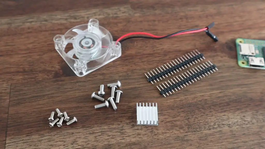
You’ll need the following components to complete this project:
- Raspberry Pi Zero 2W – Buy Here
- Pi Header Pin Set – Buy Here
- 40mm RGB Fan – Buy Here
- Aluminium Heat Sink – Buy Here
- 32GB MicroSD Card – Buy Here
- Clear Acrylic Sheet – Buy Here
- M2.5 Button Head Screws – Buy Here
- M3 Button Head Screws – Buy Here
You’ll also need some tools and equipment. If you don’t have some of these tools, have a look if you’ve got a local MakerSpace.
- Creality Ender 3 V2 – Buy Here
- Dremel Soldering Iron – Buy Here
- K40 Laser Cutter – Buy Here
- Acrylic Bending Tool – Buy Here
- (The acrylic bender above can be found on Aliexpress for about $15)
Some of the above parts and equipment are affiliate links. By purchasing products through the above links, you’ll be supporting my projects, with no additional cost to you.
Soldering Header Pins Onto Your Pi Zero 2 W
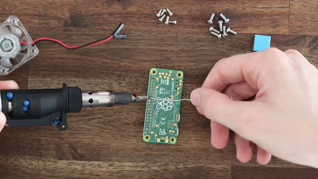
Most Pi Zero 2 W boards are sold without the header pins pre-soldered, so you’ll probably need to solder your own on. We need access to the pins in this project to power our 40mm fan, so let’s start by soldering the pins to the board. These will also be accessible through the front of the case to add a displays, sensors or other peripherals.
Just push the short end through the board and solder them on the under side of your Pi Zero 2W.
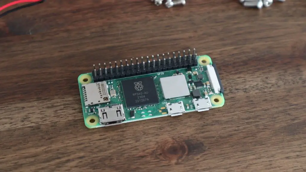
When you’re done, you should have your full set of GPIO pins accessible on your Pi Zero 2W.
Designing And 3D Printing The Case
I’m going to design the case in Autodesk Fusion360. I’ll start by creating a generic model of the Pi Zero and then design the case around it.
I decided on a basic rectangular design with the fan blowing across the Pi and out of a vented panel on the other side. I added a large acrylic window to the front so that the Pi is visible and this will also provide access to the GPIO pins.
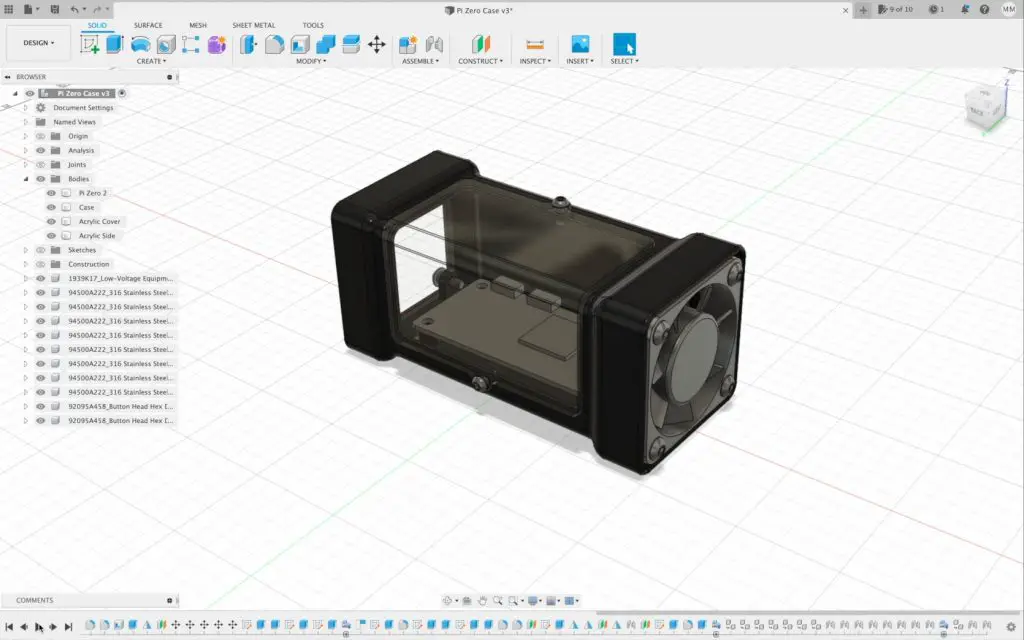
The Pi and main acrylic panel are secured with M2.5 screws and the fan and vented side cover are held in place with some M3 screws. I’m going to use a thinner 2mm clear acrylic for the two covers so that they don’t protrude from the case as much.
Download the 3D Print & Laser Cutting Files
We can then export the main body of the case for 3D printing and open it up in Cura to slice it.
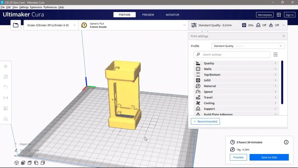
I’ve designed the case with a 1.2mm wall thickness, which is perfect for 3 layers with a 0.4mm nozzle and I’ve added in supports for the cutout on the front and the mounting points on the inside.
I’ve also added a brim around the bottom of the print so that there is a bit more contact area with the build plate. I initially tried printing the case without the brim, but due to the rounded edges, there is only a single line contacting the build plate which caused warping on subsequent layers.
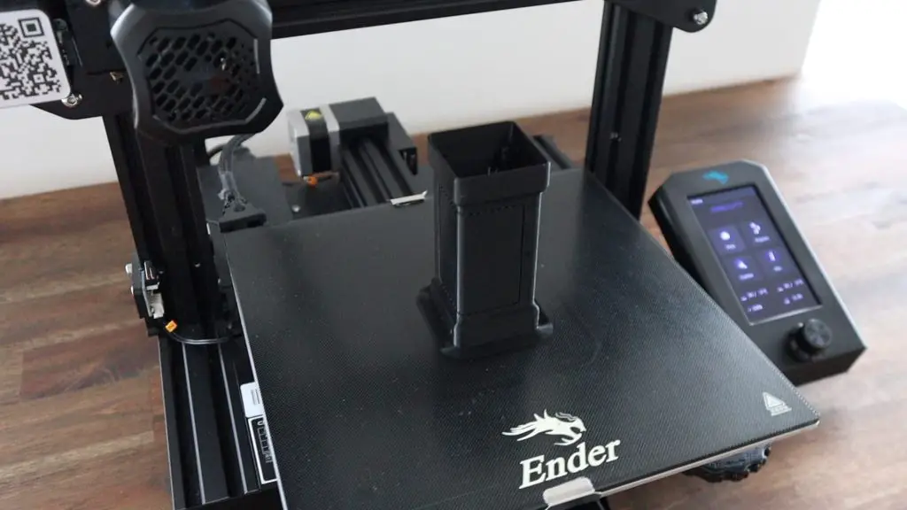
I printed the case out on my Creality Ender 3 V2 in black PLA, which took about 5 hours to complete.
Installing The Pi Zero 2 W In The Case
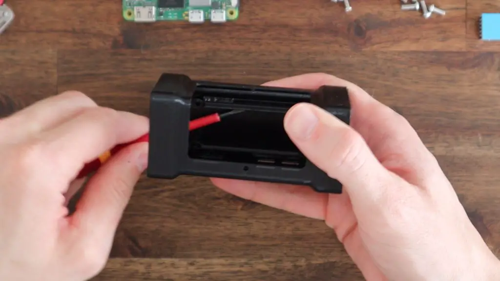
Before we can install the Pi Zero 2 W, we need to remove the brim and support material from the print.
Most of the brim can just be gently snapped off by hand, the remaining edges can be cleaned up with a sharp craft knife. The supports can then be removed using a screwdriver, craft knife or some needle nose pliers.
Make sure that you remember to remove the internal supports around the standoffs and fan mounting points.
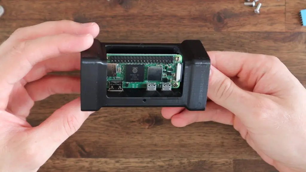
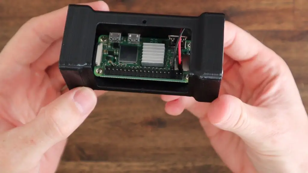
The Pi can then be mounted in the case, with the GPIO pins on the open side and the ports aligned with the cutouts on the opposite side.
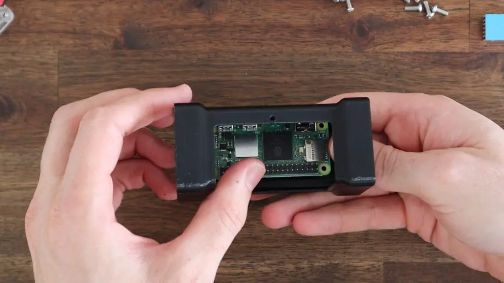
The Pi Zero 2 W is then secured using some M2.5x6mm screws which screw into the 3D printed standoffs. These standoffs also provide some room underneath the Pi for airflow as well.
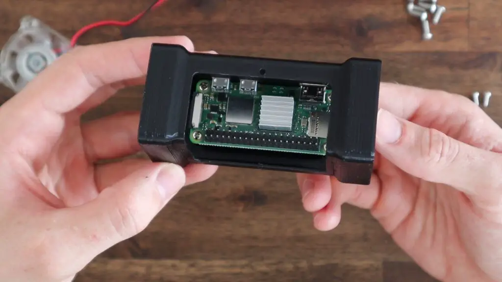
Next let’s add the heatsink to the CPU. I’m just using a small aluminium heatsink which should provide more than enough cooling with a 40mm fan. These is quite a bit of room in the case though so you can try using a different heatsink design if you’d like. There are a few options available online with taller fins. The one I’m using is quite compact and just has a peel and stick backing.
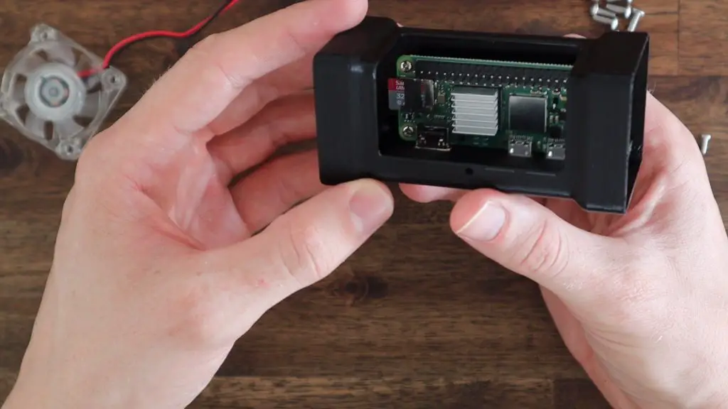
Before adding the fan, we also need to install the SD card with our operating system on it. The one I’m using came with the Pi Zero 2 W a few months back, so I assume it’s going to be the older Raspberry Pi OS Buster rather than Pi OS Bullseye but this can be upgraded at a later stage if need be.
Installing The 40mm Cooling Fan
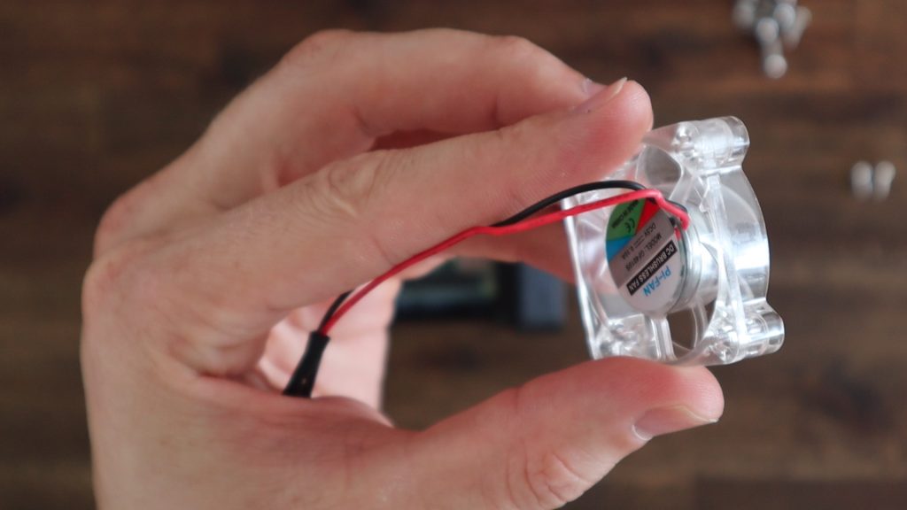
I’m using a 40mm, 5V, clear RGB fan, you can also use a plain black one if you don’t want any lights on your case. Either way, first make sure that the power cable comes out the back of the fan and not off to the side. You might need to pull the cable out of the little retaining clips on the side like I’ve done.
I originally planned on using some M3x8mm screws for the fan and opposite side panel to keep them consistent, but they don’t protrude all the way through the fan so I’ll need to use M3x12mm screws on this side and M3x8mm screws on the opposite side for the acrylic cover.
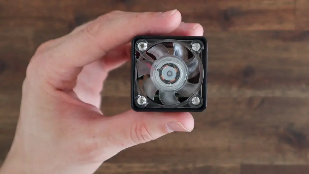
When you position the fan, make sure that the cable is on the top corner on the GPIO pin side of the case and secure it with the M3 screws. Make sure that it is mounted as shown so that it is pushing air into the case rather than pulling it out of the case.
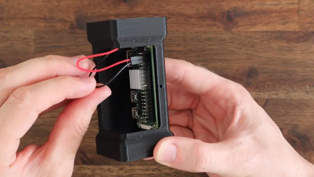
Now we can plug the fan into the GPIO pins to power it.
Most of these 5V fans can run on either 5V or 3.3V. 5V will give you more power and 3.3V will be a bit quieter, so try either depending on your use case. You need to plug the black wire from the fan into any ground pin and the red wire from your fan into any 5V power or 3V3 power pin.
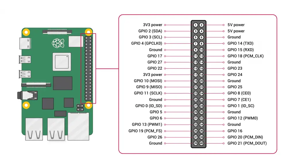
The 5V and ground pins are the two pins in the front as shown here:
The 3V pin is the pin on the end in the second row. I’m going to use 3.3V as the fan is then a bit quieter as it turns slower.
Now we’re got the fan hooked up, we can start making our acrylic covers for the ventilation side and the main front and top of the case.
Making The Acrylic Covers For The Pi Zero 2 W Case
I drew the up in Inkscape to match the ones modelled in Fusion360.
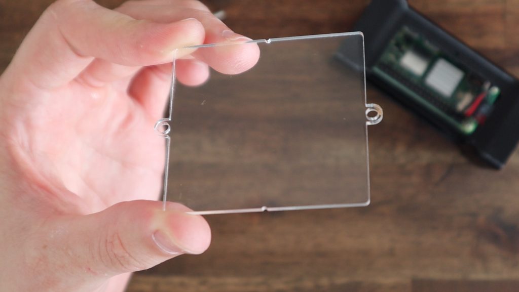
The front cover has a screw hole on each end and some notches on the sides to indicate where it should be bent.

Download the 3D Print & Laser Cutting Files
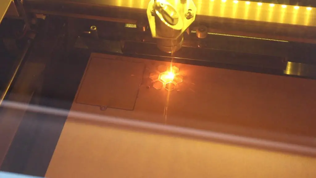
The ventilation cover has the same form factor and mounting holes as the 40mm fan and I’ve added some hexagon ventilation holes which are similar to my other case designs.
I then cut these out on my laser cutter from 2mm clear acrylic.
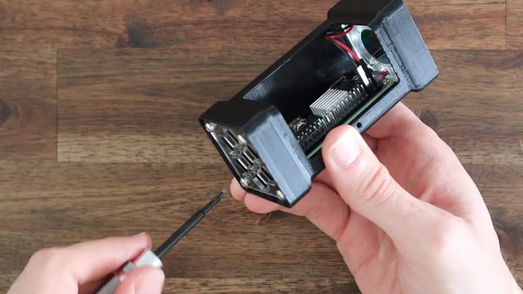
As mentioned earlier we’ll be mounting the ventilation cover with four M3x8mm screws and the main cover with two M2.5x6mm screws.
Install the ventilation cover first, using the four M3x8mm button head screws. The cover is symmetrical so can be installed in any orientation.
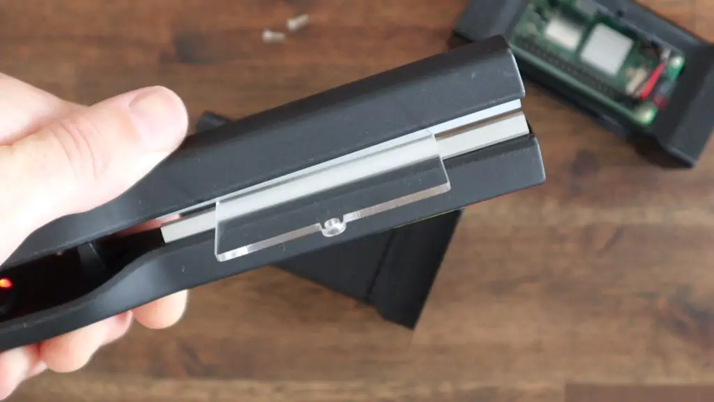
Before we can mount the main cover, we need to bend it 90 degrees to follow the shape of the case.
We first need to peel off the protective film and we can then use a heating tool to soften the acrylic along the bend line – the line through the two notches on the sides.
The tool looks like a hair straightener but it’s actually made to bend small sections of acrylic sheets and you can buy them online for about $15 (from Aliexpress). Be careful when working with the tool and the acrylic once it is soft, it is very hot and can easily cause burns.
With the acrylic soft, I’m going to use a second print to bend the acrylic to get a nice clean line. This is not entirely necessary, you can just use the case you’ve already got printed, I just want to support the whole bend while it is hardening.
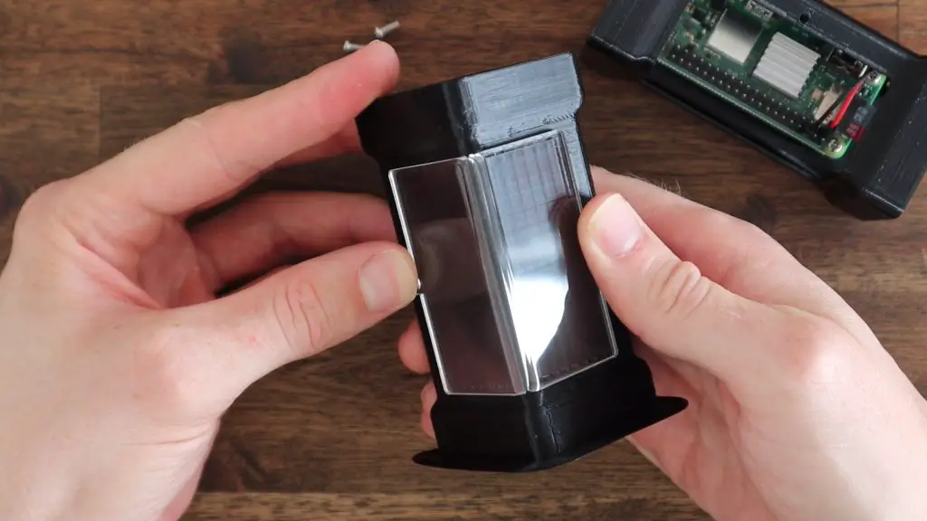
Now we need to add the two M2.5 screws to hold it in place.
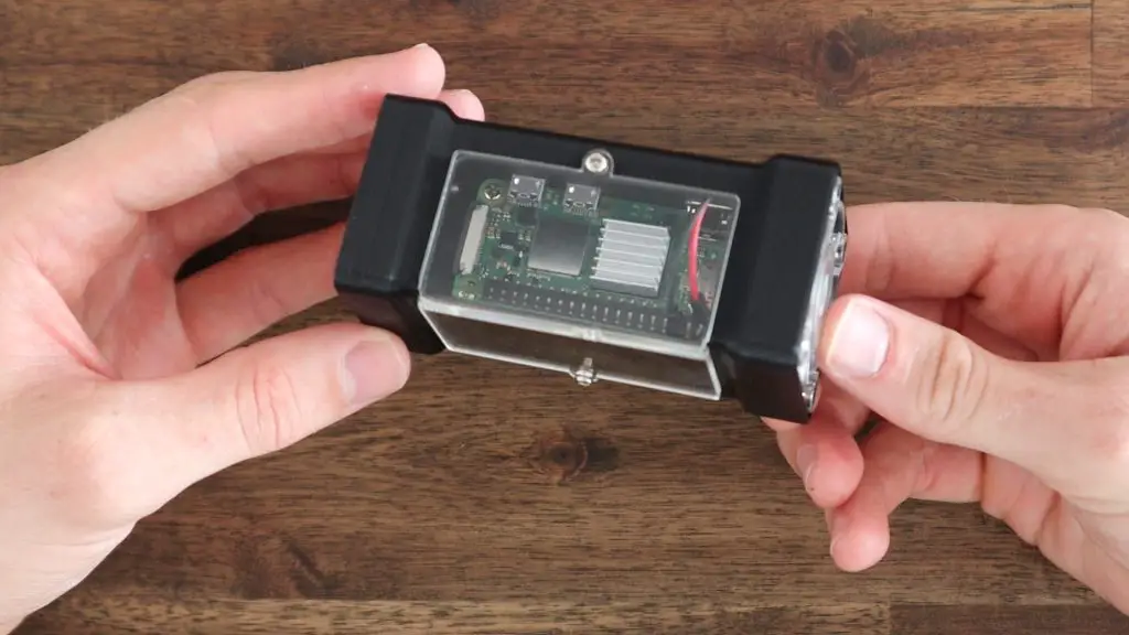
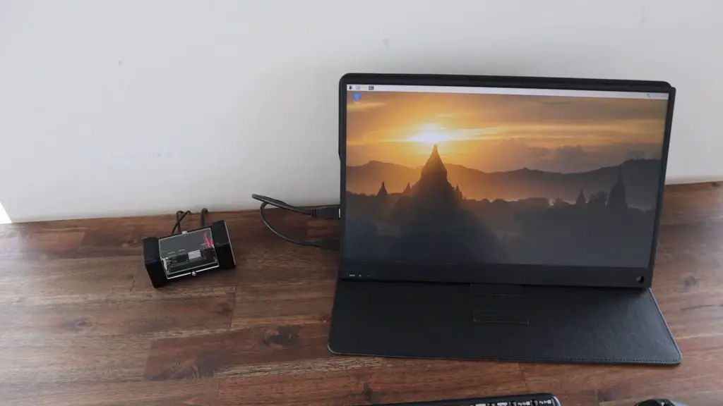
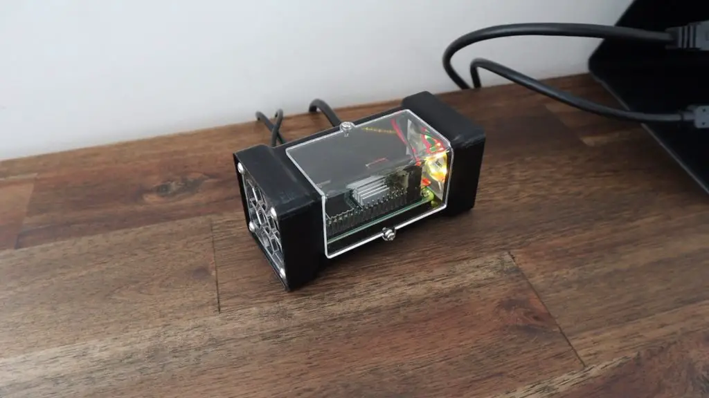
With that done, the case is now complete. So let’s turn boot up the Pi and see how it looks.
Booting Up The Pi Zero 2 W
Depending on what you’re going to be doing with your Pi, you can now plug in your power supply, monitor and and USB devices and boot it up.
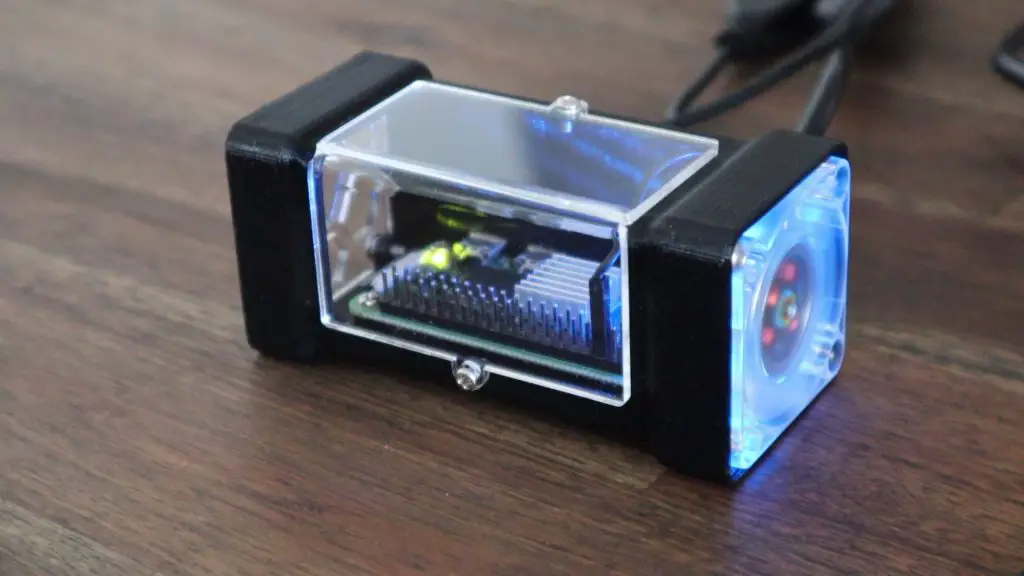
I quite like the look of the RGB LEDs on the fan, I think this came out quite nicely. You can also add a fan grill or dust filter to the inlet if you’d like, I quite like the fan being open and visible.
This makes for a really neat compact computer for a number of projects. I’ve been running Pi-hole on a Pi Zero W for a bit over a year now and that’s worked well. I’ve also used one as a security camera using MotionEyeOS.
Let me know what you use yours for in the comments section below, and let me know what you think of the case design. What would you add or do differently?
Hey Michael,
Thanks for making this write-up. I am looking to use this with my Ender 3 V2 printer. Would you be able to make a verison of the raspberry pi housing that would slide onto the v-slot rails?
-Thank You
I’ll have a look at how to best integrate a v-slot mount onto the case, it’s a nice package to use with a 3D printer.
Iagree with Kru….I use a RPi 0 two on all of my printers and am going to print this case for all of them….on Thingiverse there are v-Slot covers available and I have printed them out. Think I might be able to glue one of them to the bottom of the case. You do nice work.