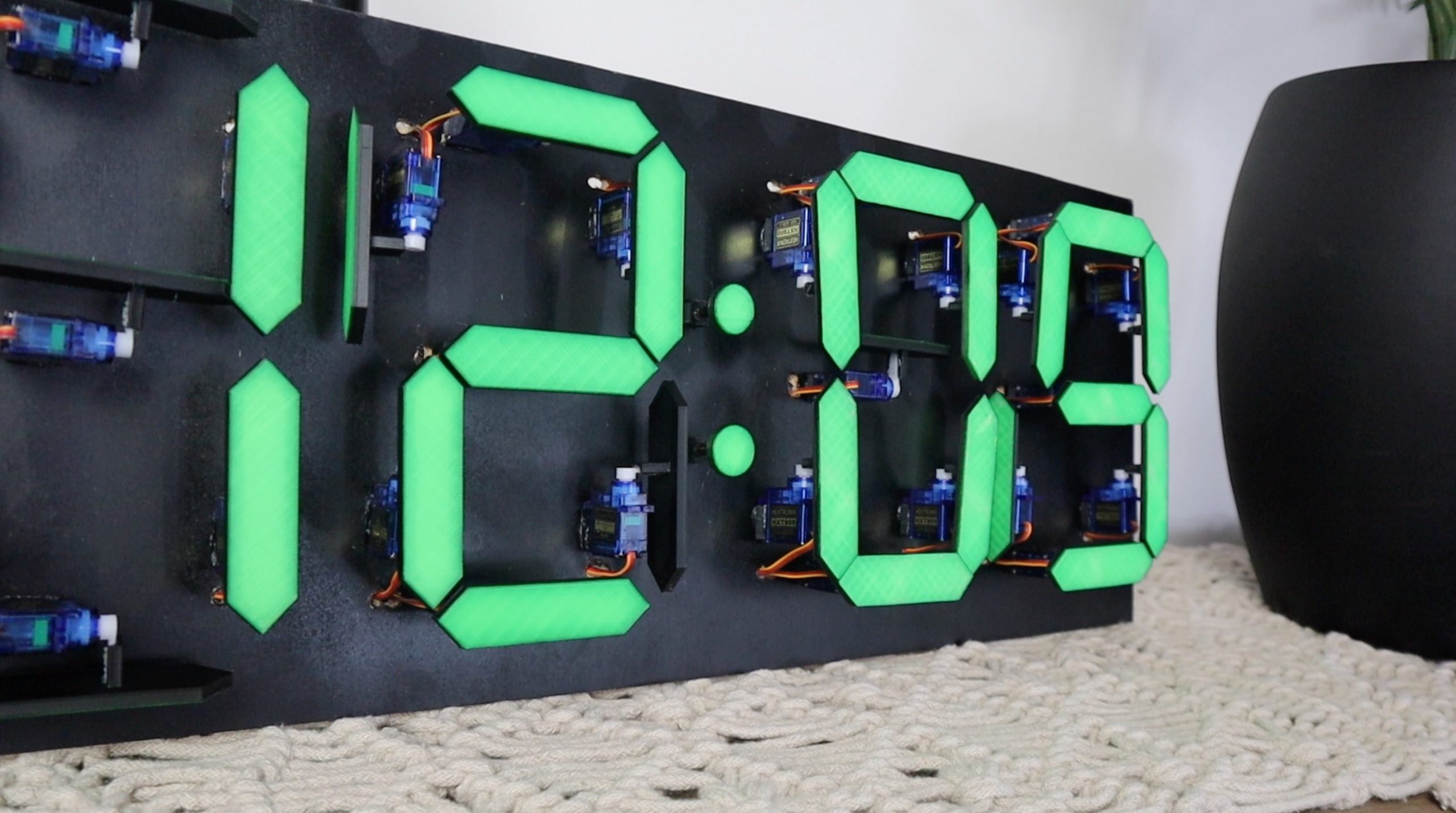
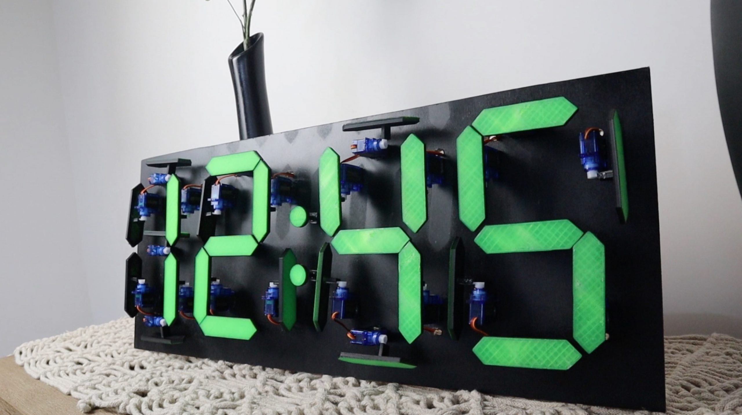
I built a countdown timer a couple of months ago using a two digit mechanical 7 segment display which was driven by 14 servos and an Arduino Mega. It came out quite well and a number of people suggested doubling up on the display to build a clock. The only problem was that the Arduino was already running short on PWM IO and I needed to double up on the outputs. Fortunately, someone pointed me in the direction of these PCA9685 16 channel PWM drivers, so I used them and a DS1302 real time clock module to build a mechanical 7 segment display clock which uses 28 servos and is now driven using an Arduino Uno.
Here’s a video of the build and the clock in operation, else read on for the full step by step instructions, code and 3D print downloads.
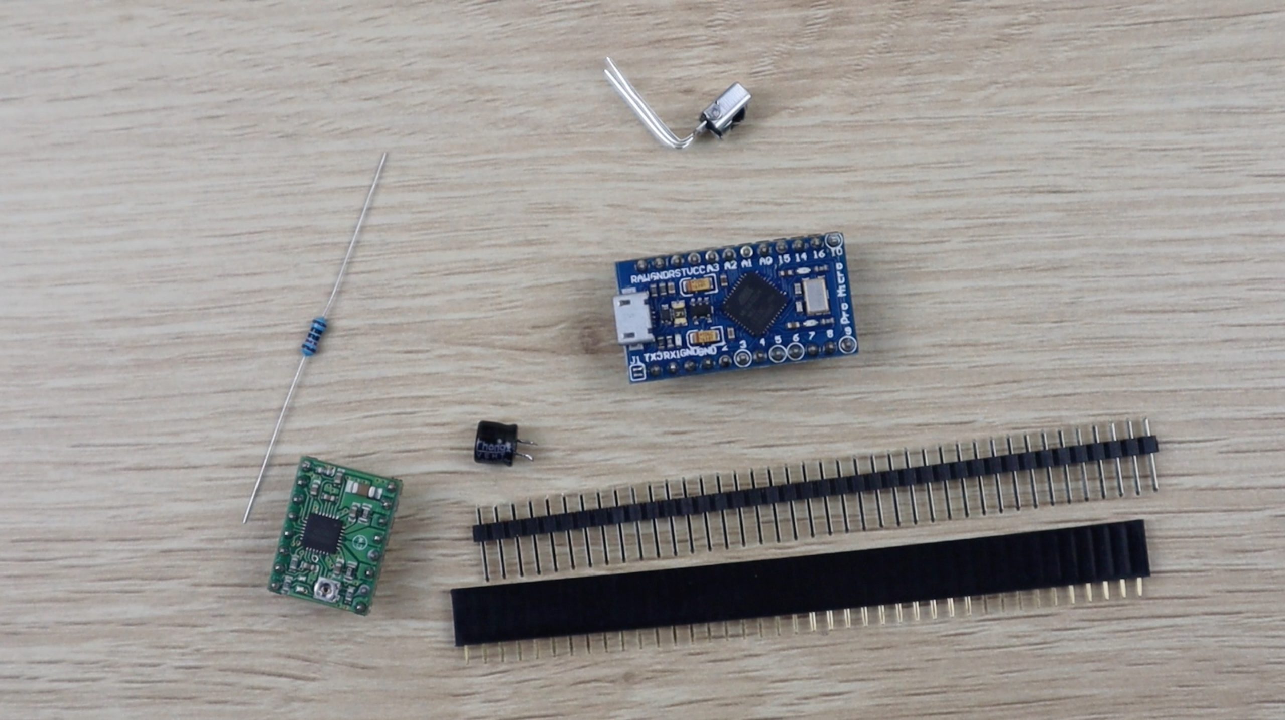
What You Need To Build Your Own Mechanical 7 Segment Display Clock
- Arduino Uno – Buy Here
- DS1302 Clock Module – Buy Here
- 2 x PCA9685 16Ch Servo Drivers – Buy Here
- 28 x Micro Servos – Buy Here
- Ribbon Cable – Buy Here
- Male Pin Header Strips – Buy Here
- Female Pin Header Strips – Buy Here
- 3mm MDF – Buy Here
- Black Spray Paint – Buy Here
- 5V 5A Battery Elimination Circuit – Buy Here
- 12V Power Supply – Buy Here
You’ll also need to 3D print some components. If you don’t have a 3D printer and you enjoy making things, you should definitely consider getting one. The one below is affordable and produces pretty high quality prints for the price. If you don’t want to get a 3D printer yet, there are a couple of online services which will print components for you and ship them to you.
How To Build Your Clock
3D Print The Components
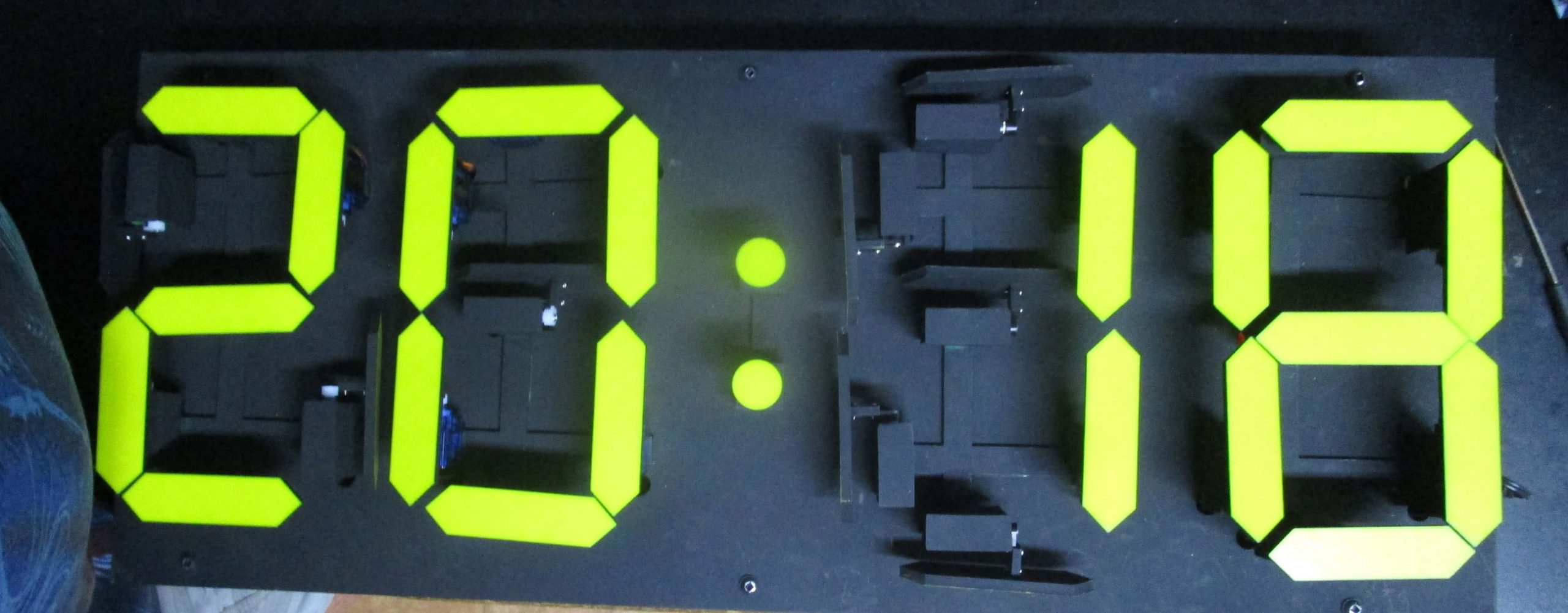
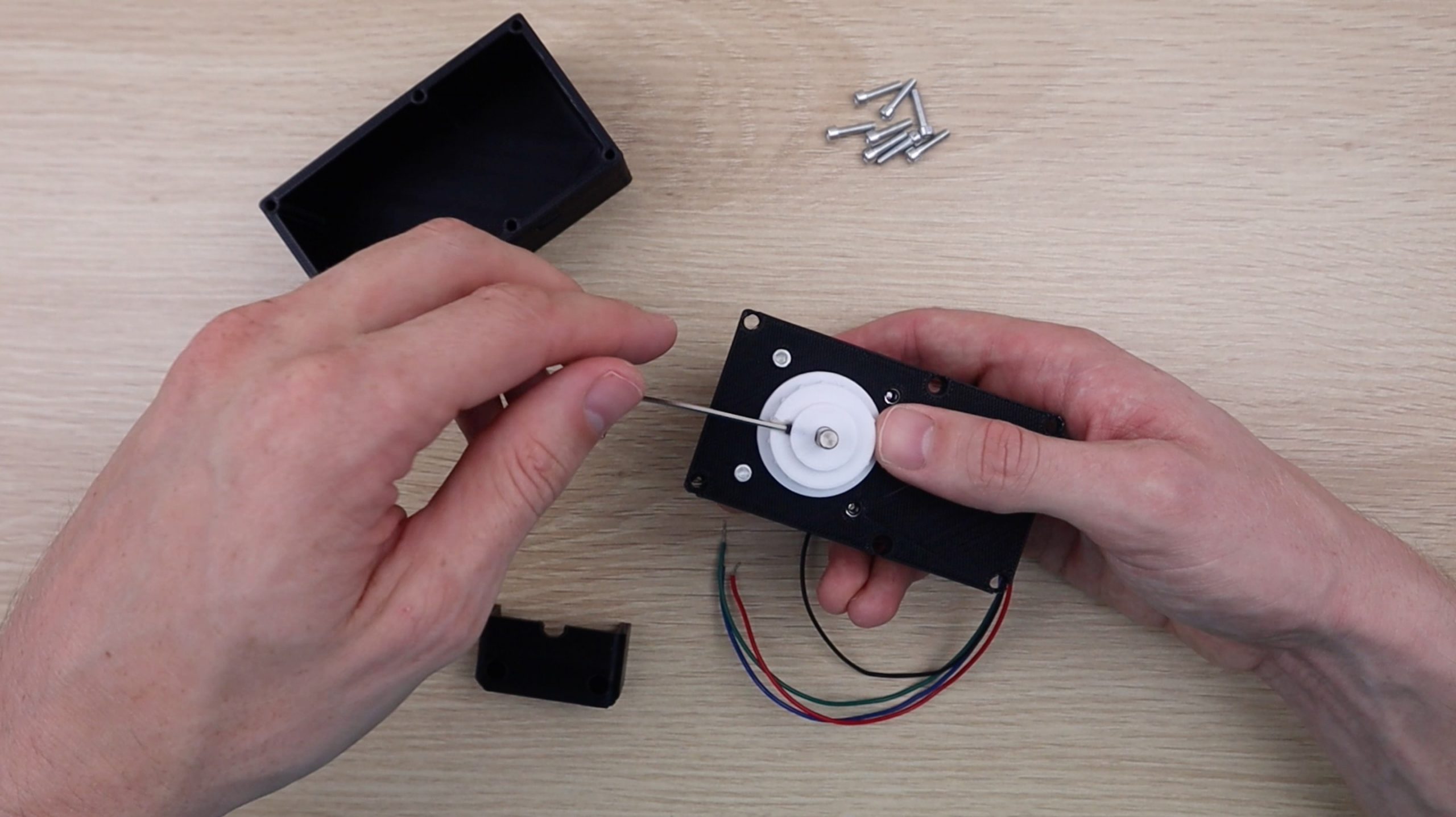
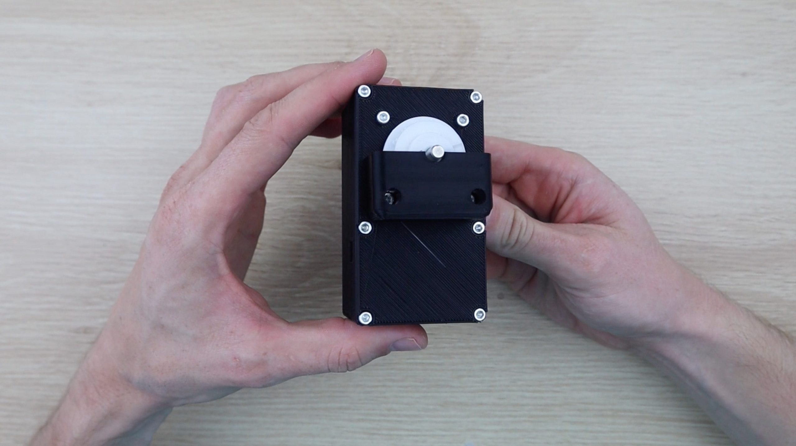
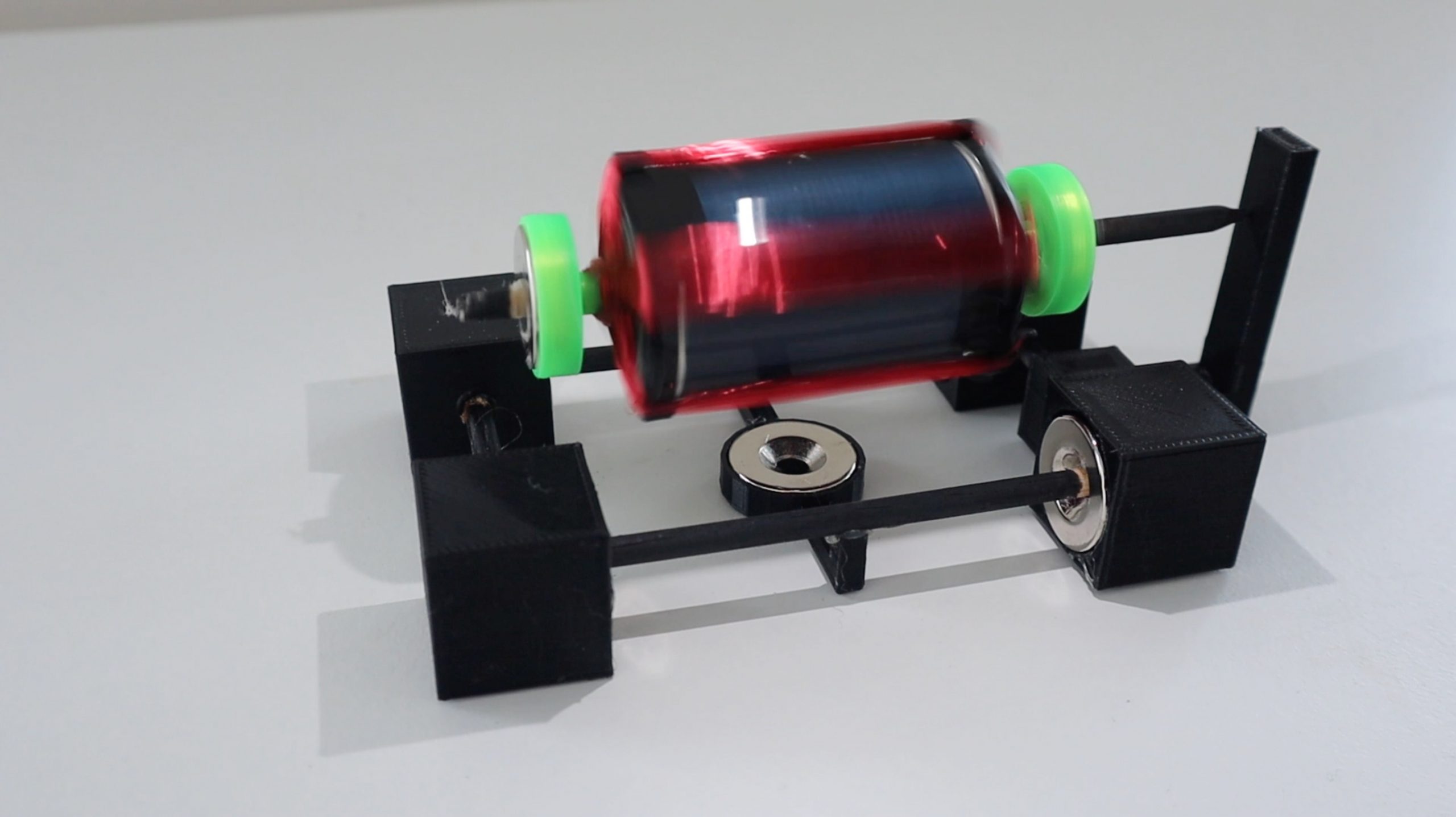
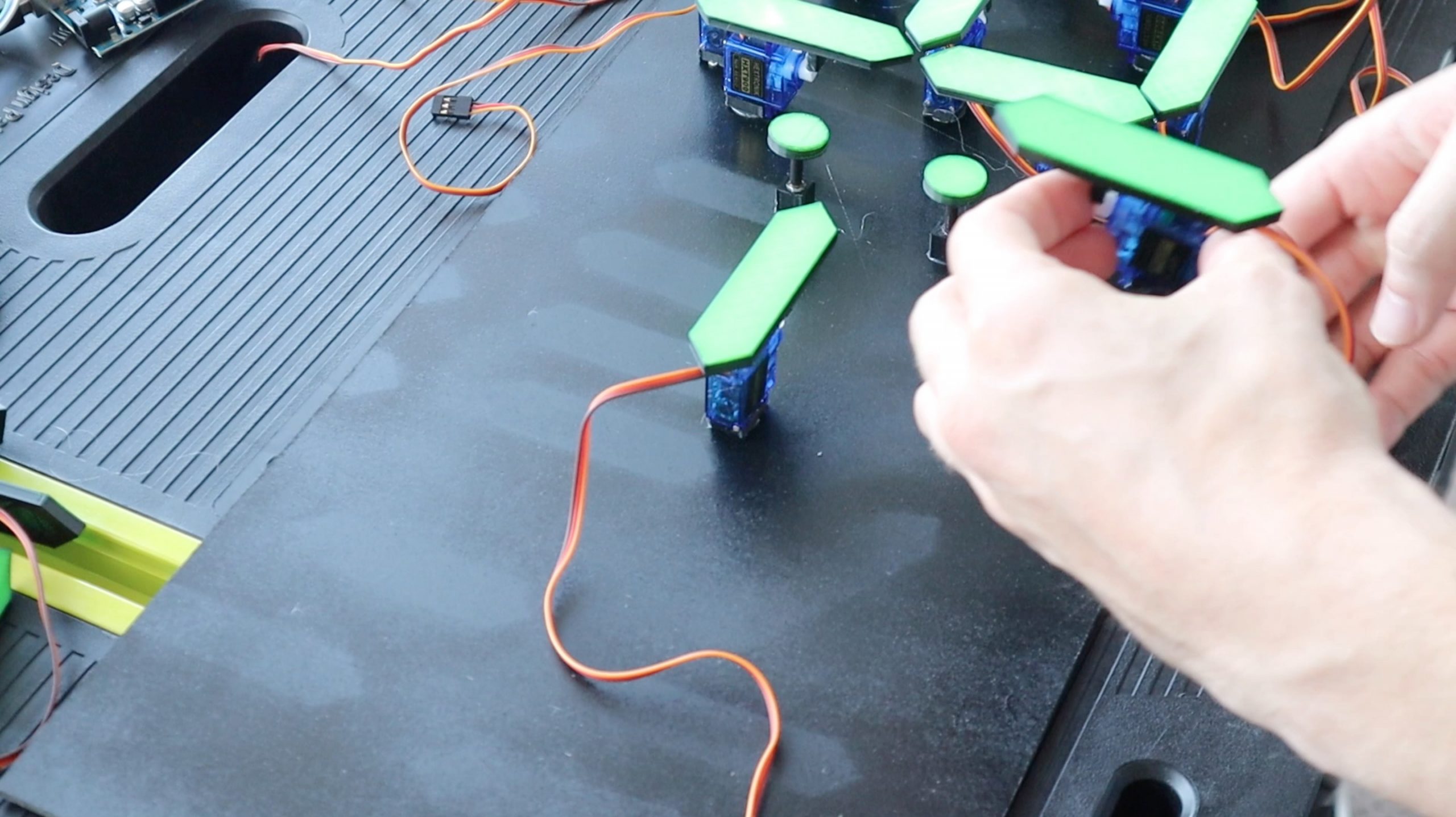
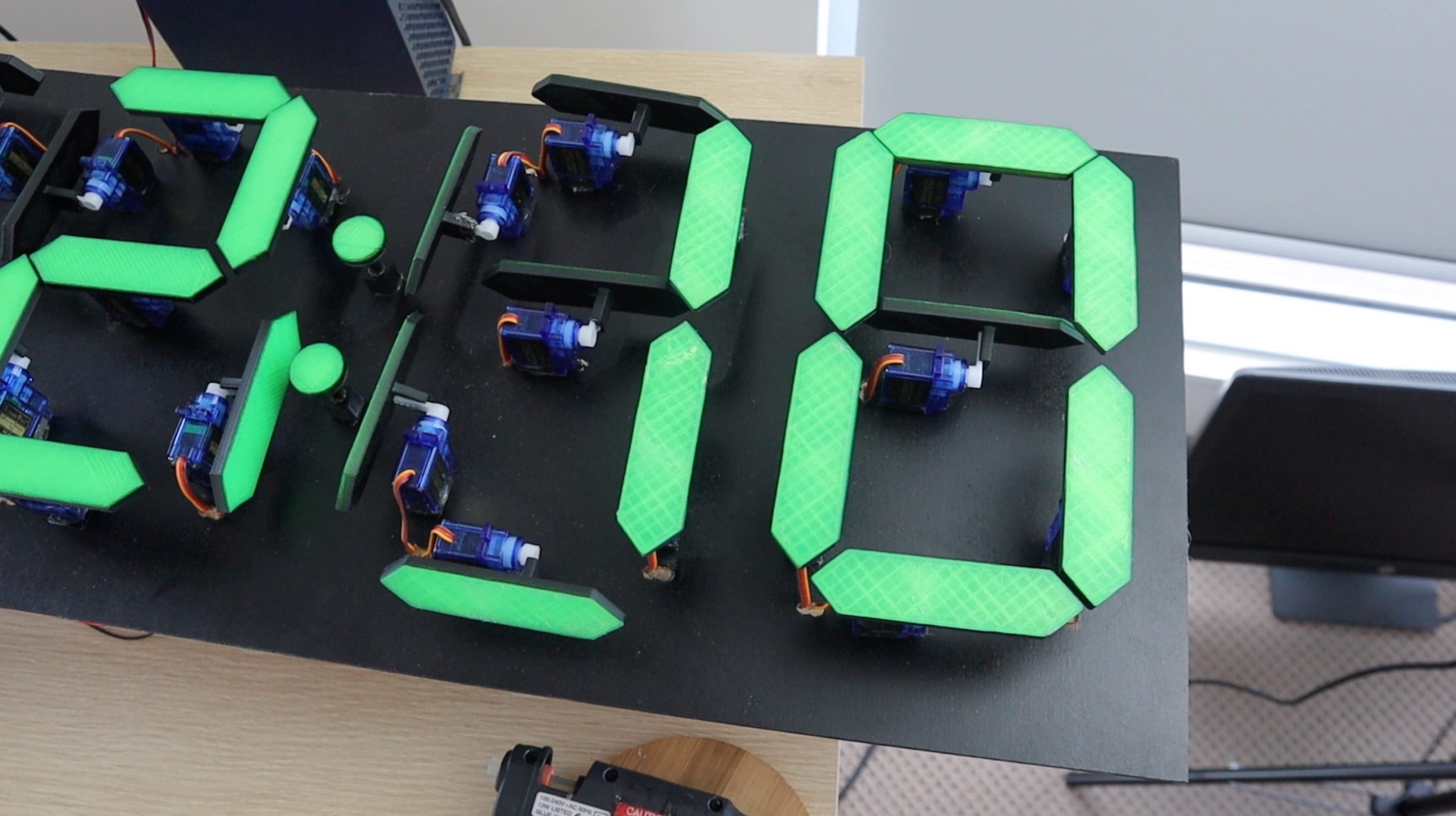
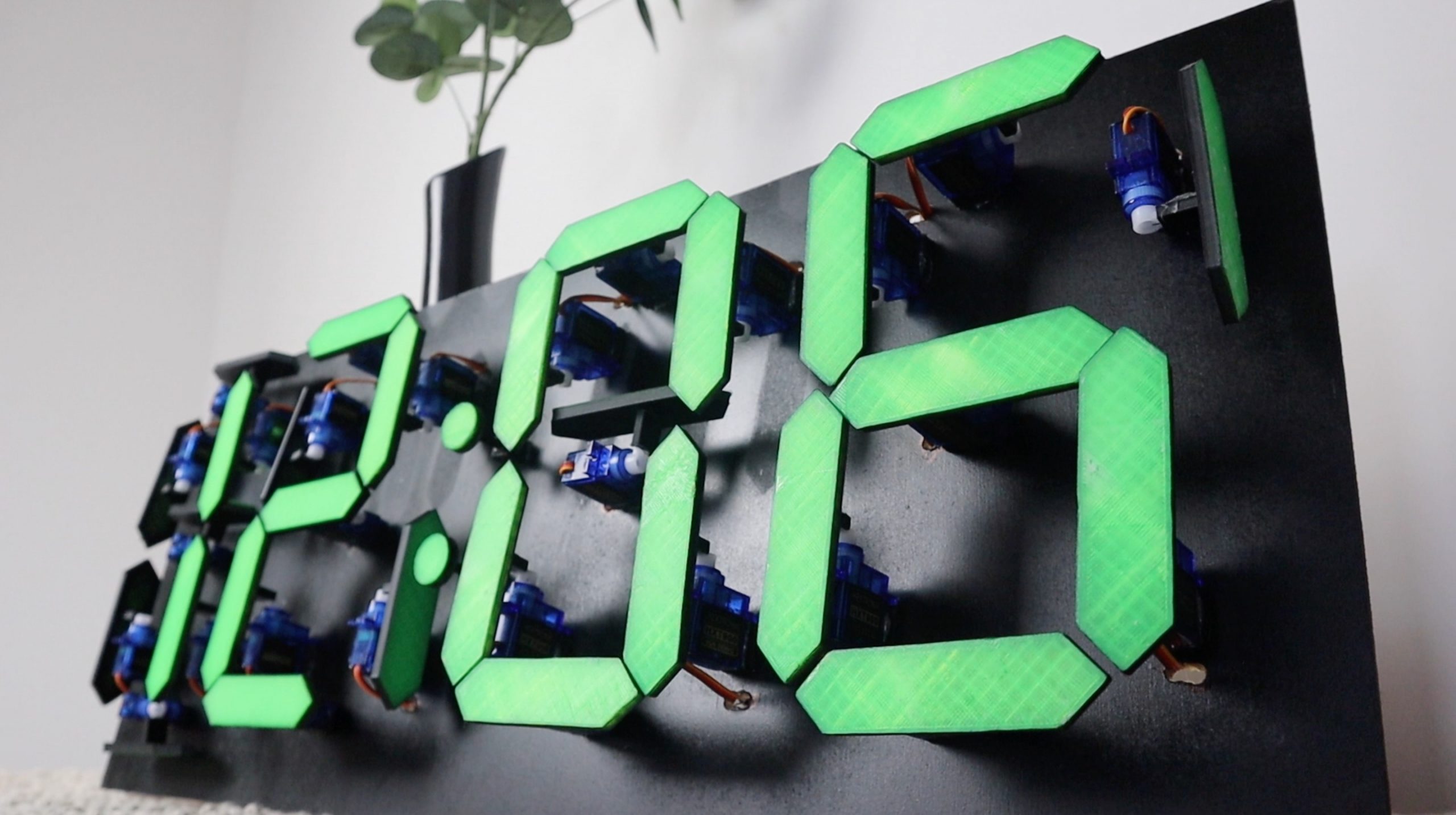
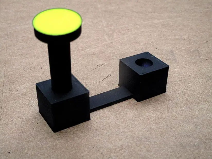
I started off by designing an individual 7 segment display numeral which could be actuated using a micro servo for each segment. The micro servos move each segment vertically when on and 90 degrees to the side when off.
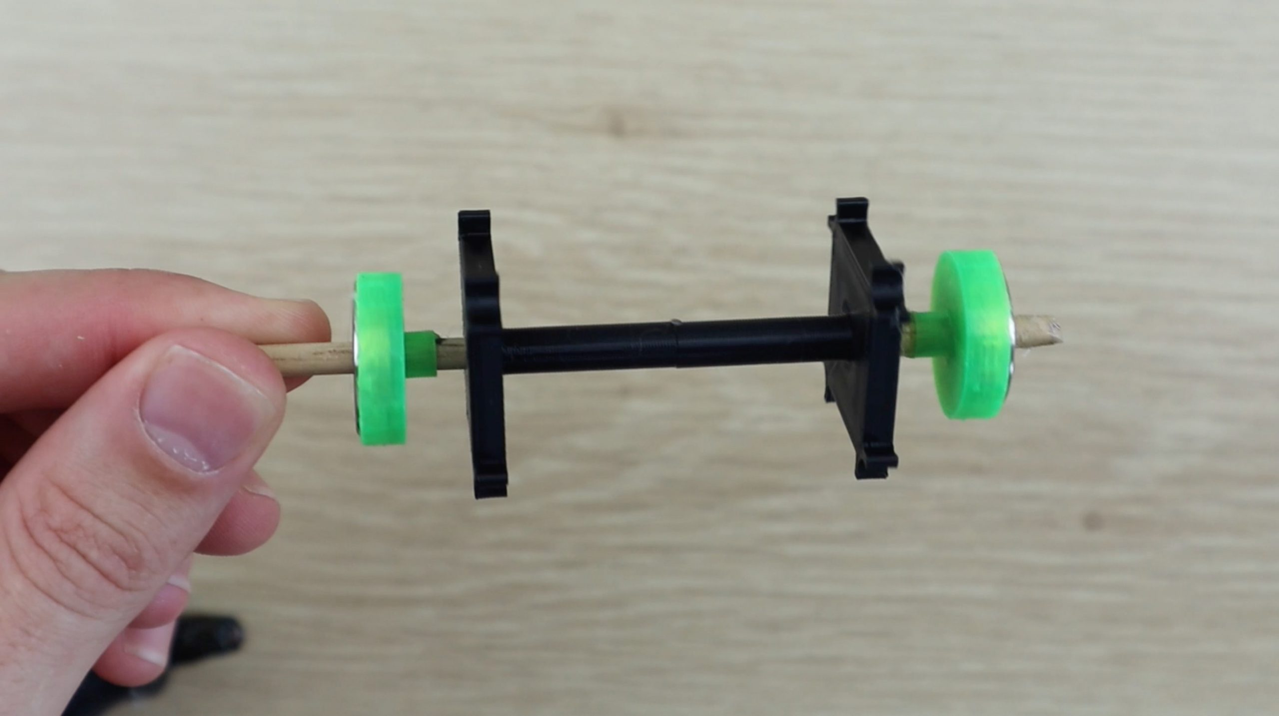
The segments are designed to glue straight onto the standard servo arm so that no additional hardware is required.
Download The 3D Print Files – 7 Segment Clock 3D Print Files
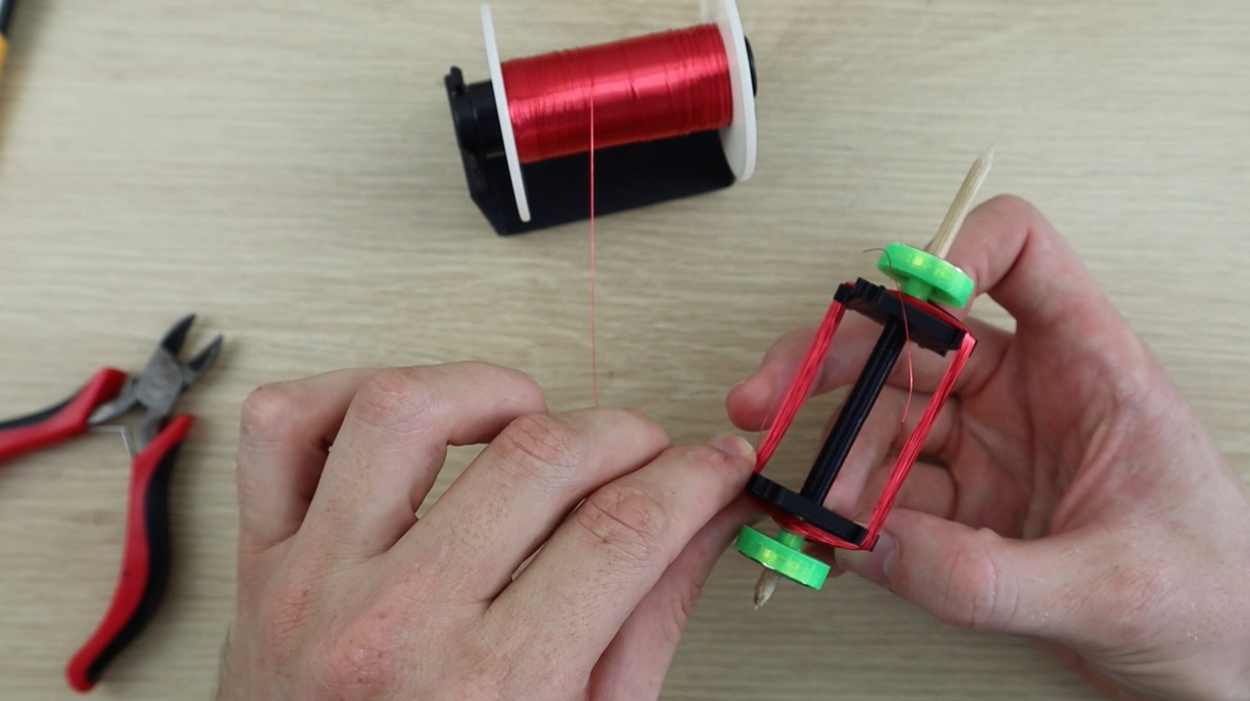
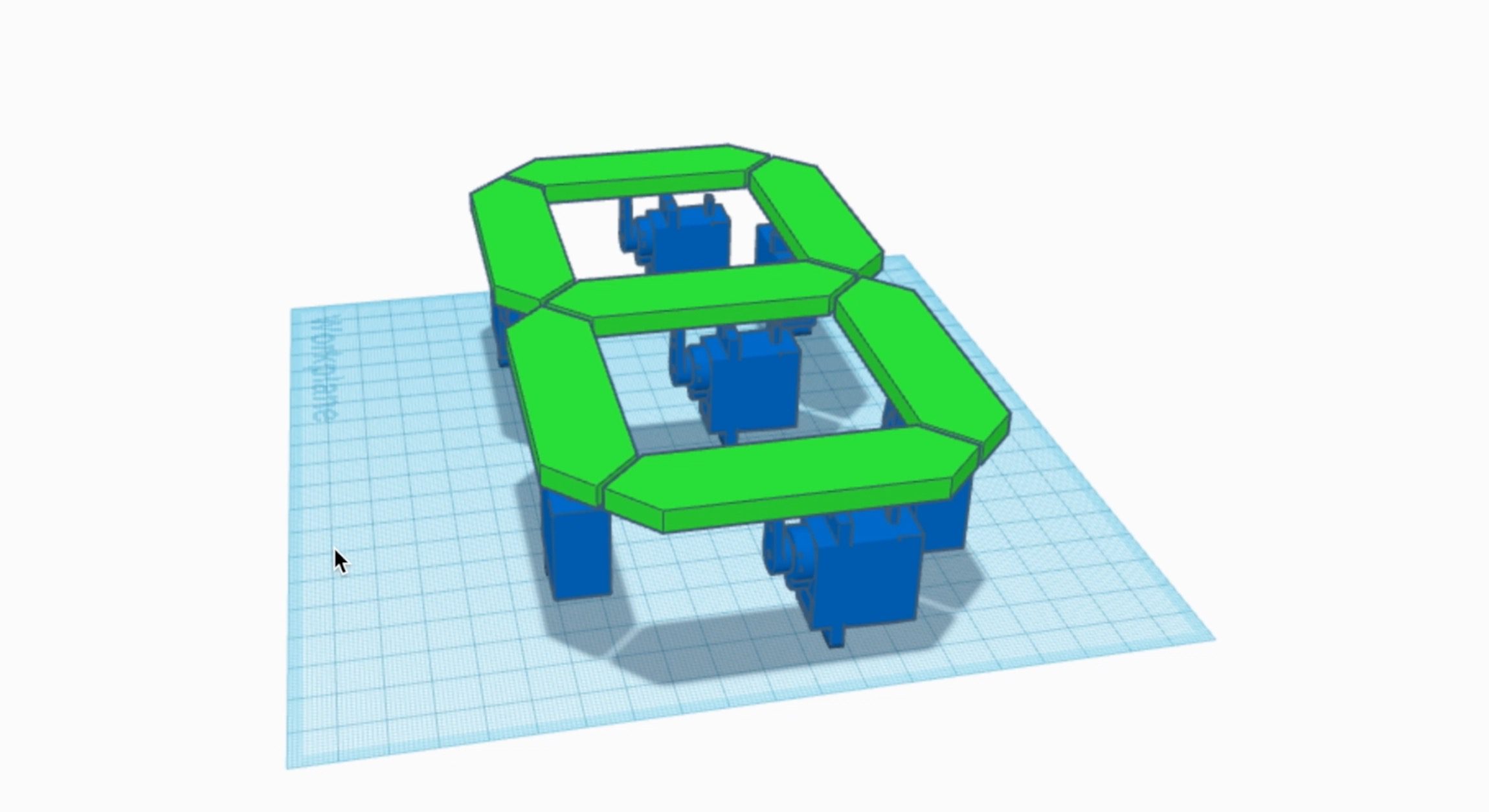
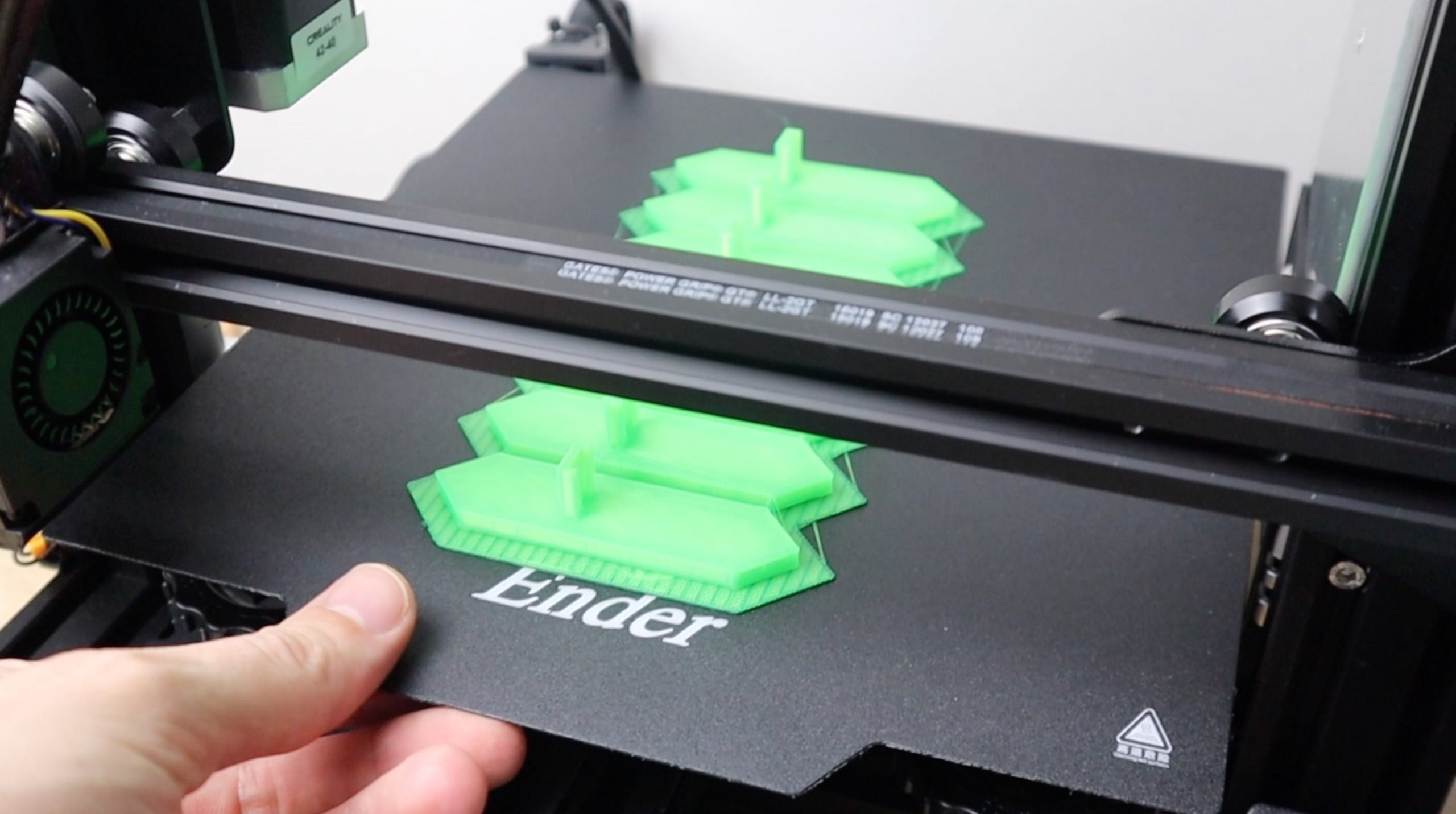
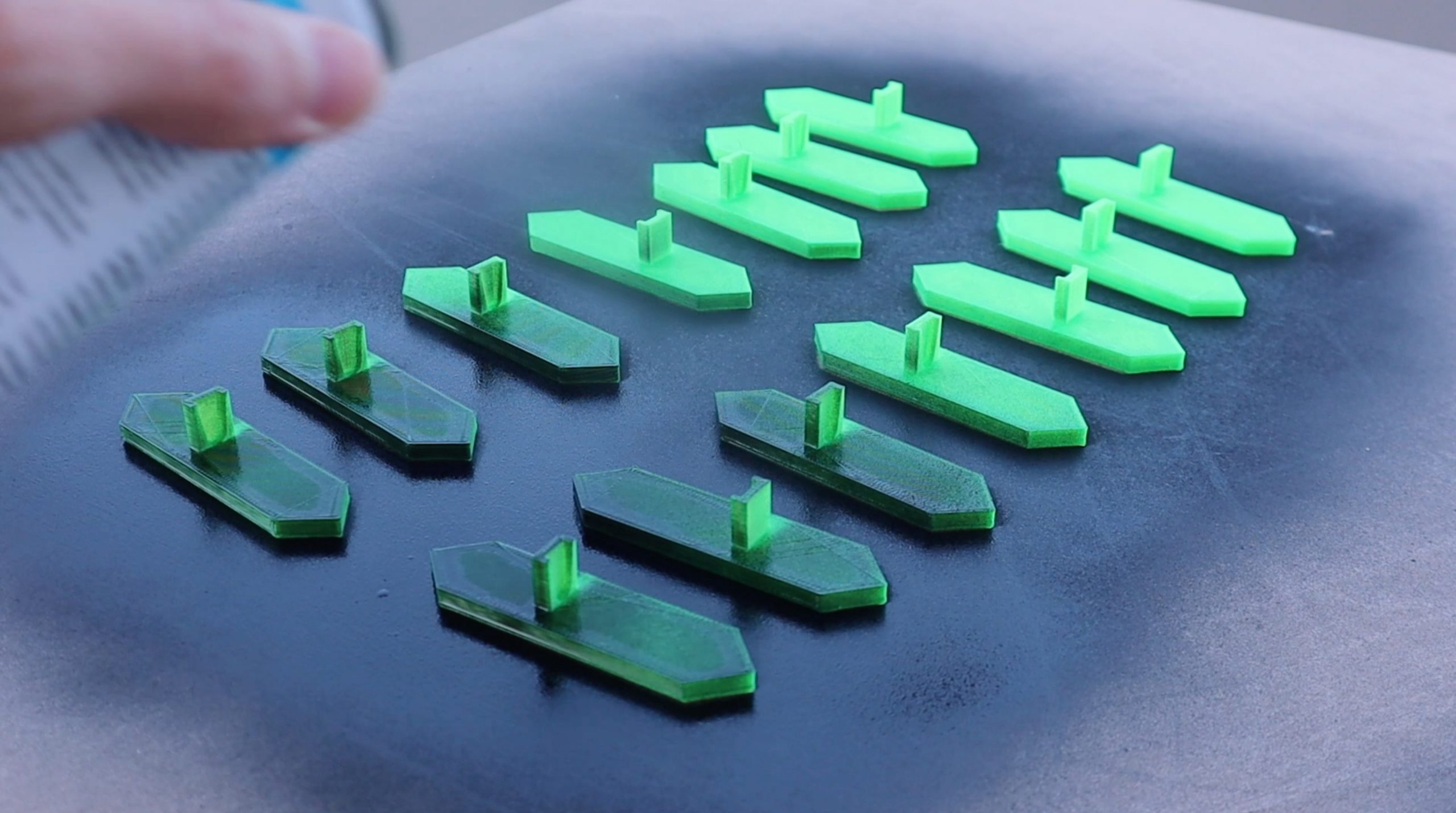
You’ll need to 3D print the 28 segments using a translucent green PLA with 15% infill. You’ll also need to print out the 28 base blocks to support the servos as well as the two dots for the centre and their bases. You could use any brightly coloured PLA for the segments, red would create a more traditional looking 7 segment display. Use black PLA for the spacer blocks and bases so that they’re not visible on the black background.
Solder The Wiring Harnesses
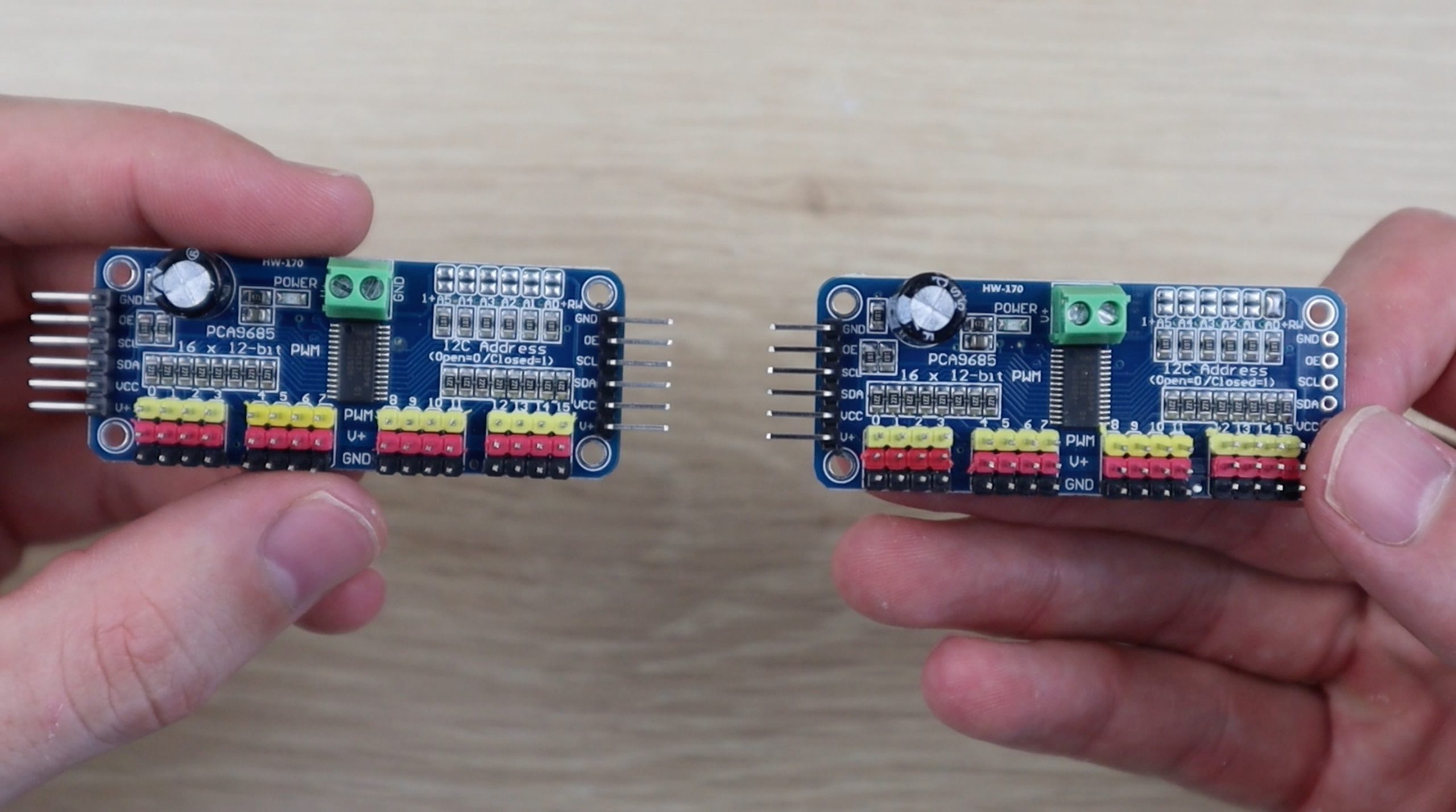
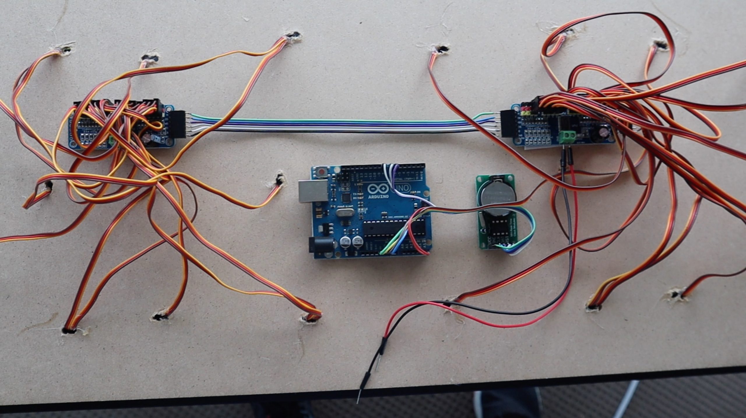
I used two PCA9685 16 channel PWM drivers which allow you to control up to 16 servos on each board and chain up to 62 boards together over an I2C interface, which uses only two IO pins on your Arduino. This means that you could theoretically independently control up to 992 servos with just two IO pins. We’re going to be using one for the two hour digits and one for the two minute digits.
To chain the two together, you need to first add a pin header to the other side of the first board and then change the address on the second board so that it’s uniquely identified.
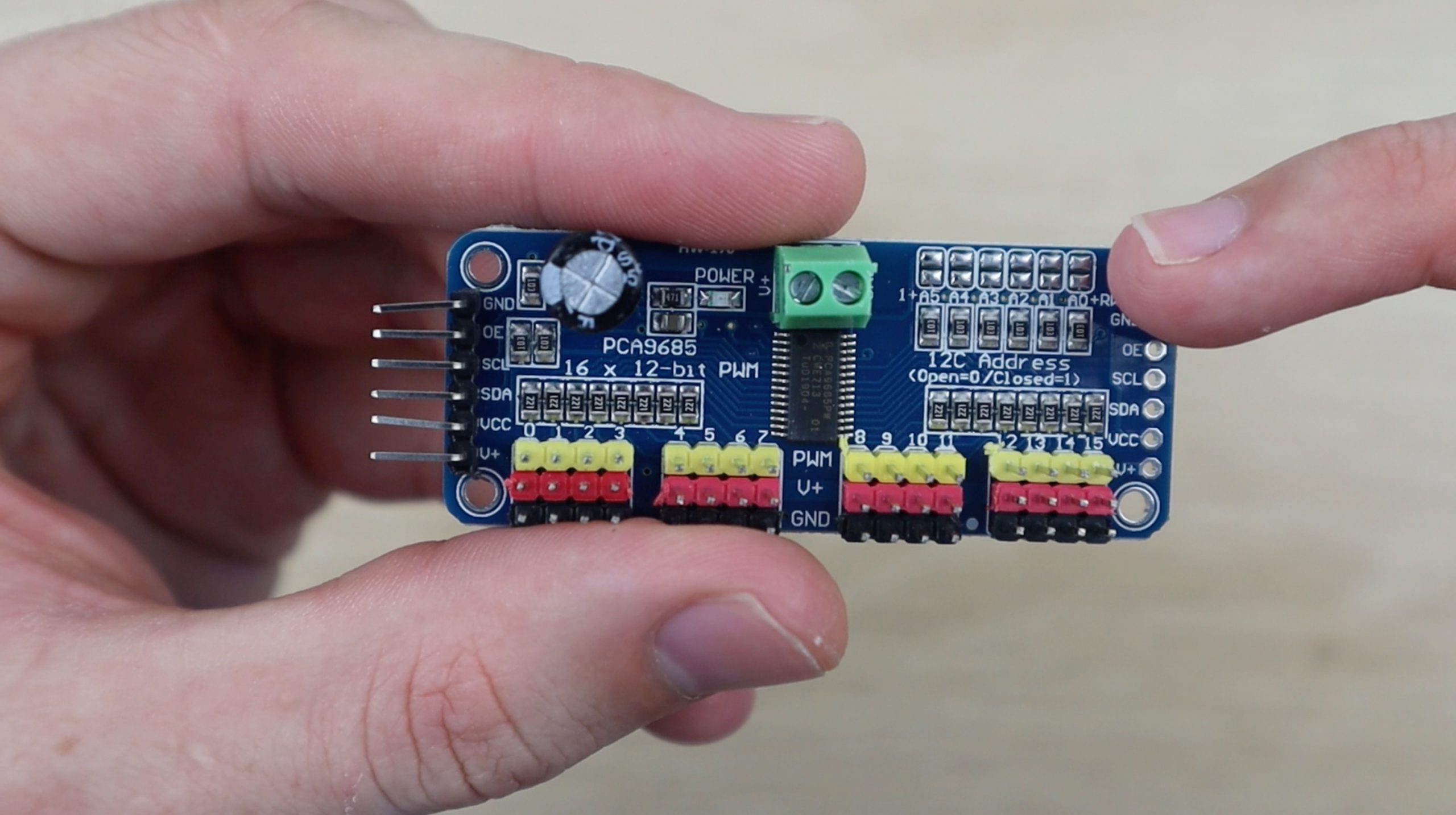
This is done by bridging the small terminals on the top right of the board. They work like dip switches, allowing you to set a different address for each board. You only need to bridge one set of terminals on the far right for this project.
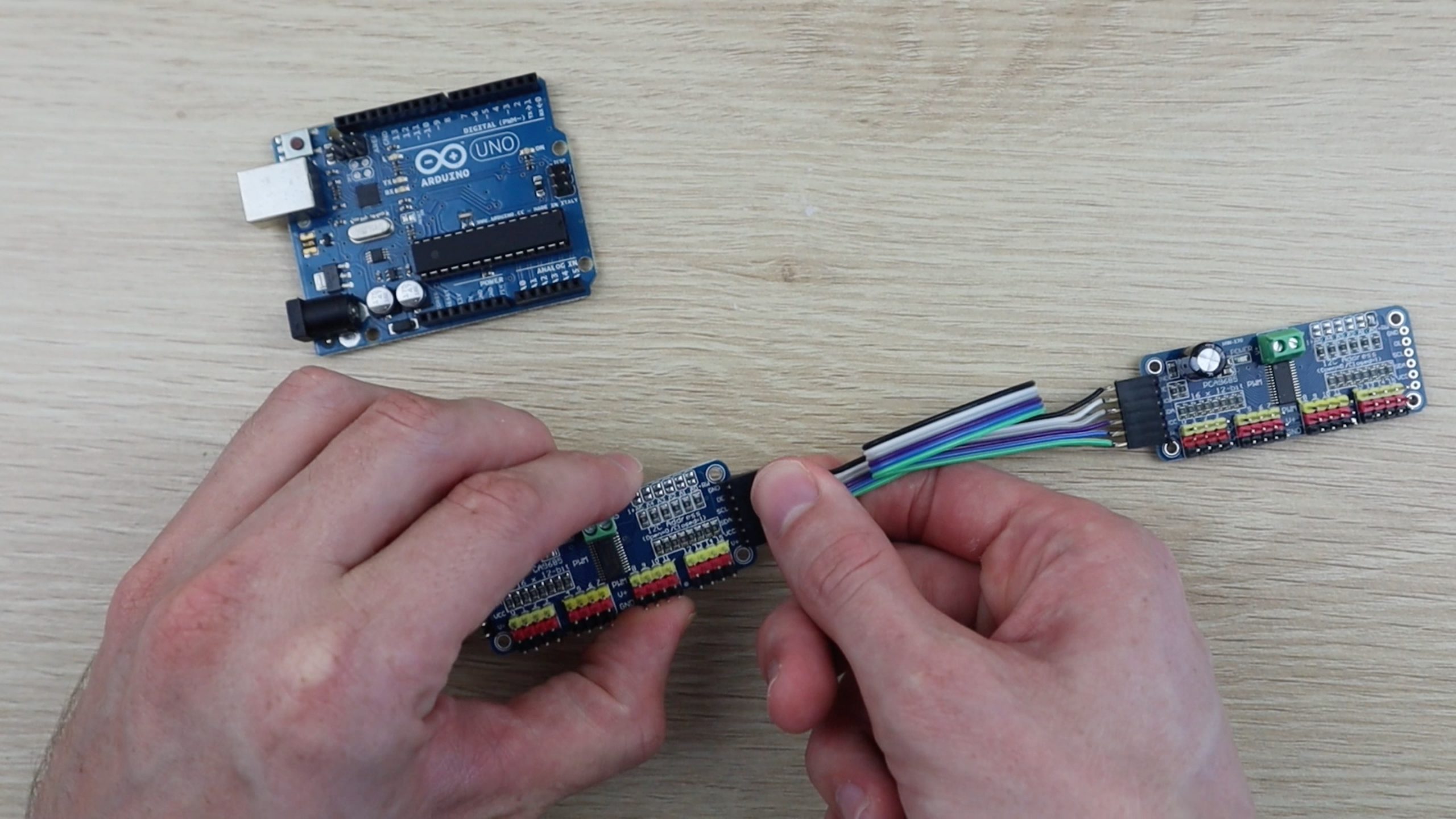
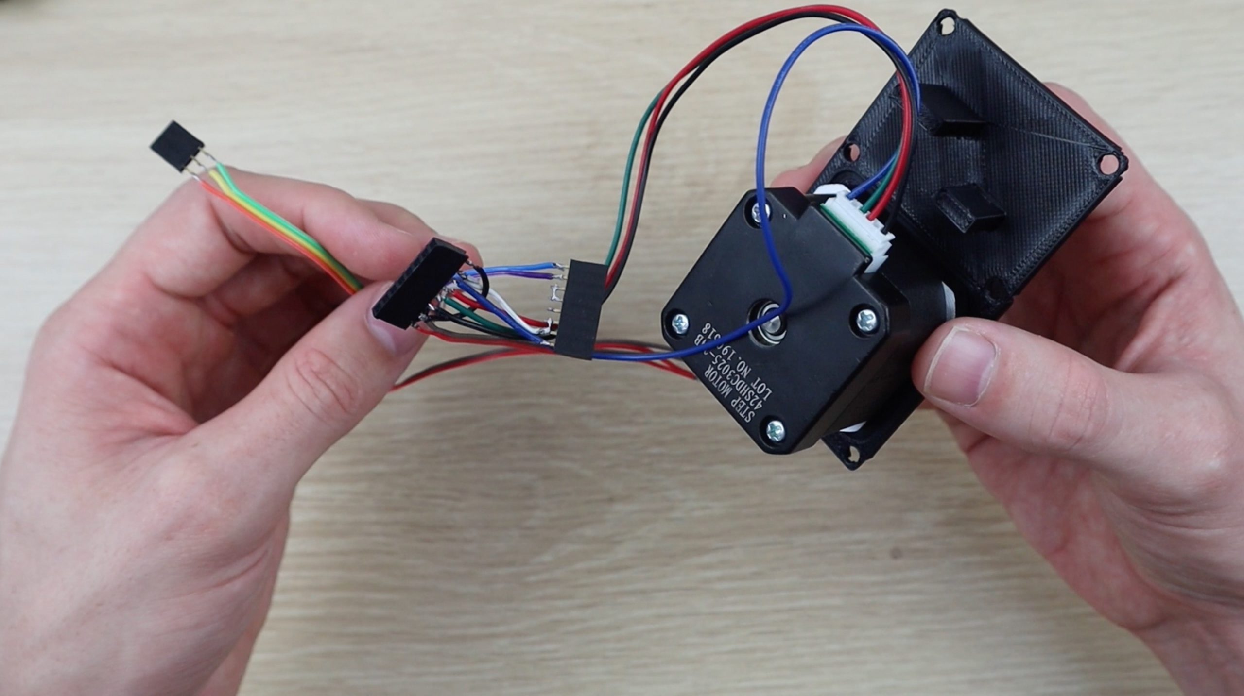
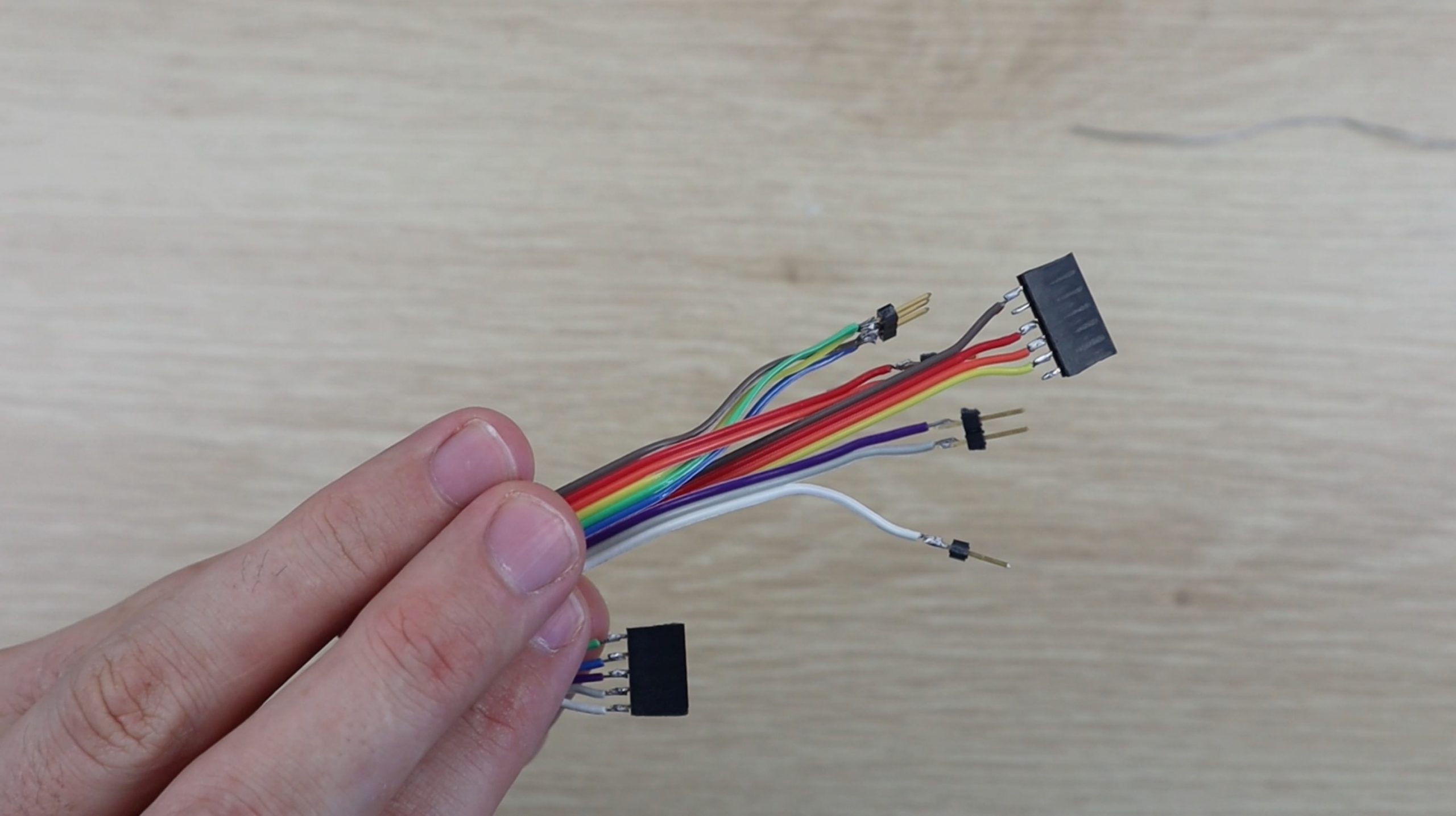
Once you’ve added the header strip and changed the address on the second board, you’ll need to make up the cable to chain the two together.
You’ll also need a wiring harness to connect these two boards to the Arduino along with the clock module.
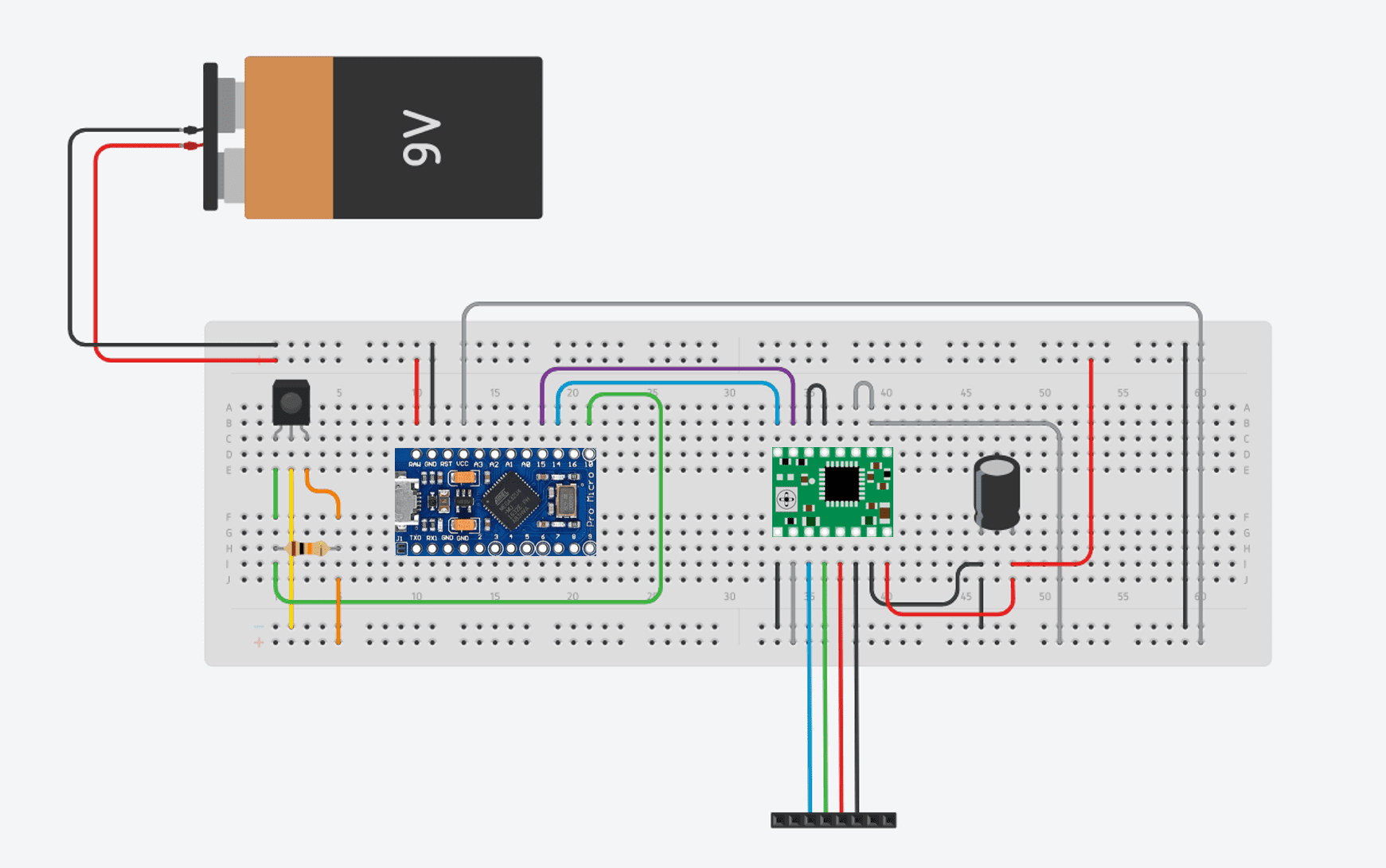
Here’s the circuit diagram:
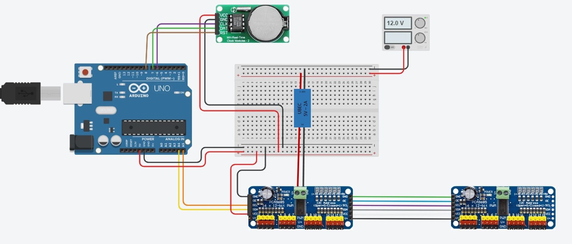
You’ll need to connect both the clock and the servo control boards to your Arduino’s GND and 5V pins to supply them with power. You’ll also need to connect the I2C interface on the servo control boards to your Arduino pins A4 and A5 (SDA and SCL respectively). Note that you’ll only connect one board to the Arduino, the second board is connected to the first board and will access the Arduino through this connection. Lastly, you’ll need to connect your real time clock module pins CLK, DAT & RST to pins 6, 7 & 8 respectively.
Power is supplied to the servos through the terminals on the servo driver boards. You’ll need to connect your 5V 5A BEC to your 12V power supply and then connect the leads to the terminals on one of the boards. You don’t need to connect both, if you’ve connected all of the pins between the two boards together then power will be supplied across your connection as well. You’ll also need to power your Arduino, this can be done from the same 12V power supply.
Assemble The Clock Display
Once the 3D printed segments are complete, you’ll need to spray the back and sides of the segments black to match the background so that they’re less visible when turned away. If you leave them green then you’re still going to land up with a thin visible line when the segment is turned 90 degrees. Also spray the back and sides of the dots so they’re less visible from the side.
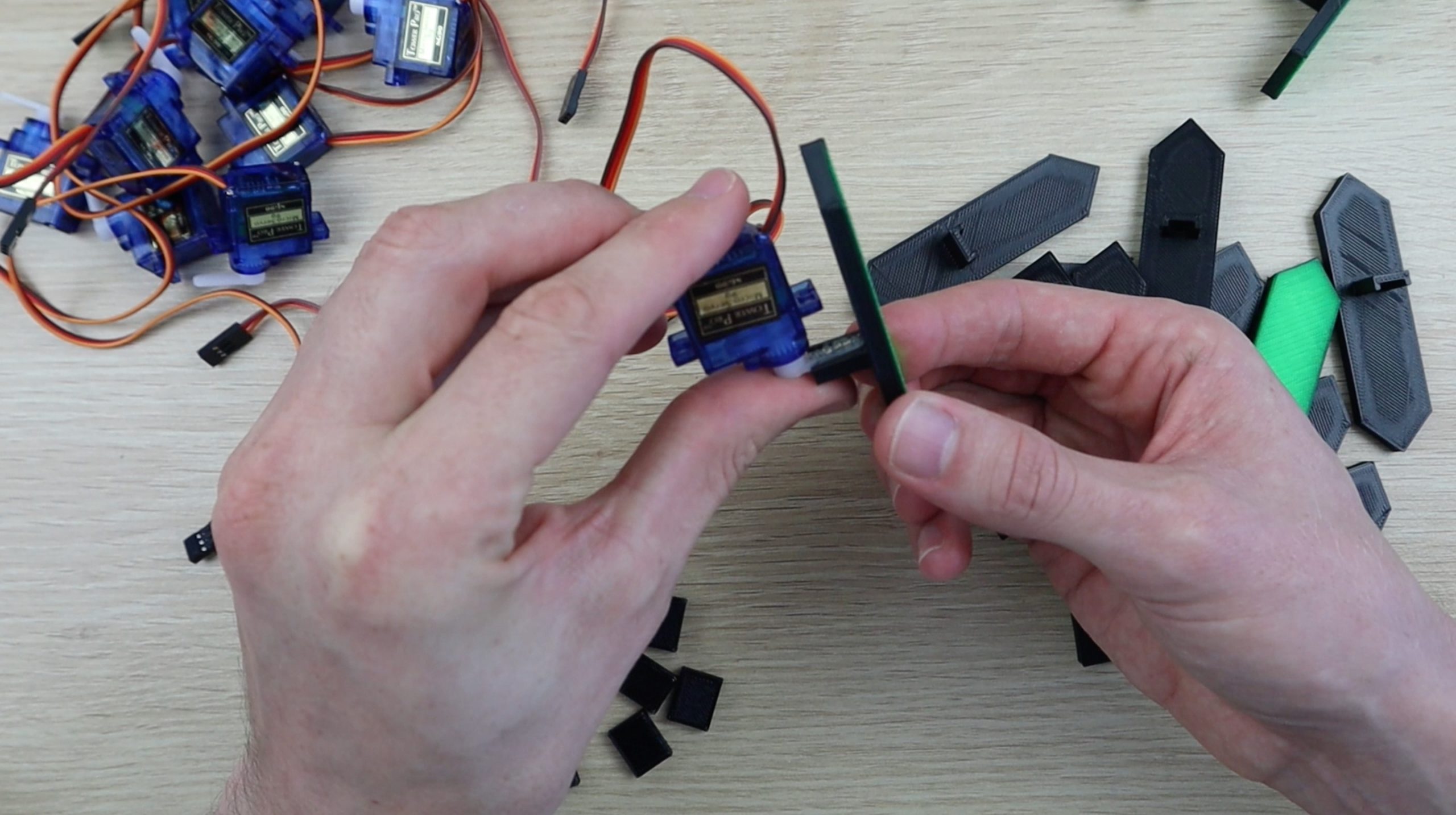
Next glue the segments onto the servo arms using hot melt glue. It’s easiest to put the arms onto the servos and then glue the segment onto the servo and arm assembly, this also allows you to check that you glue it on straight.
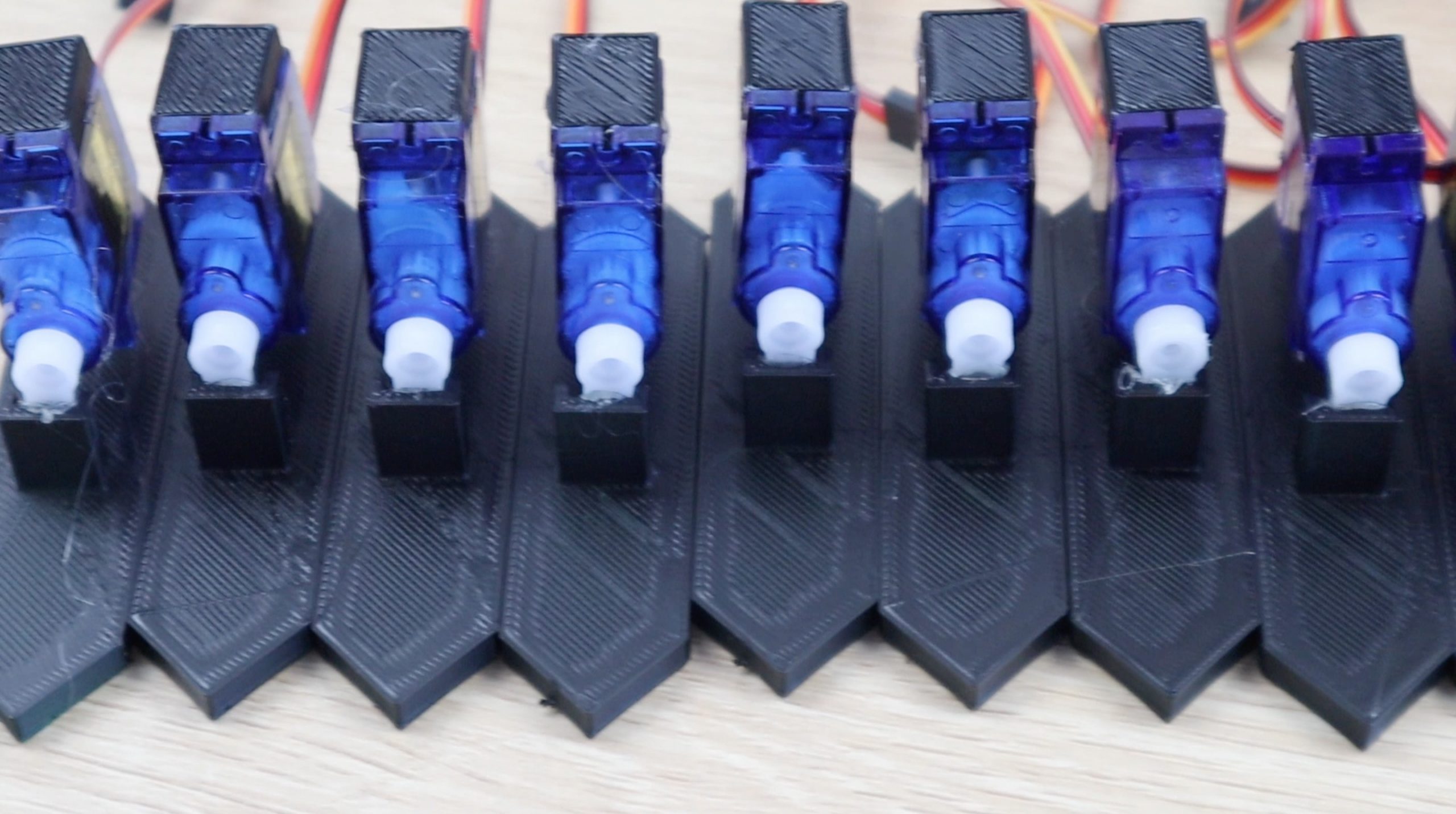
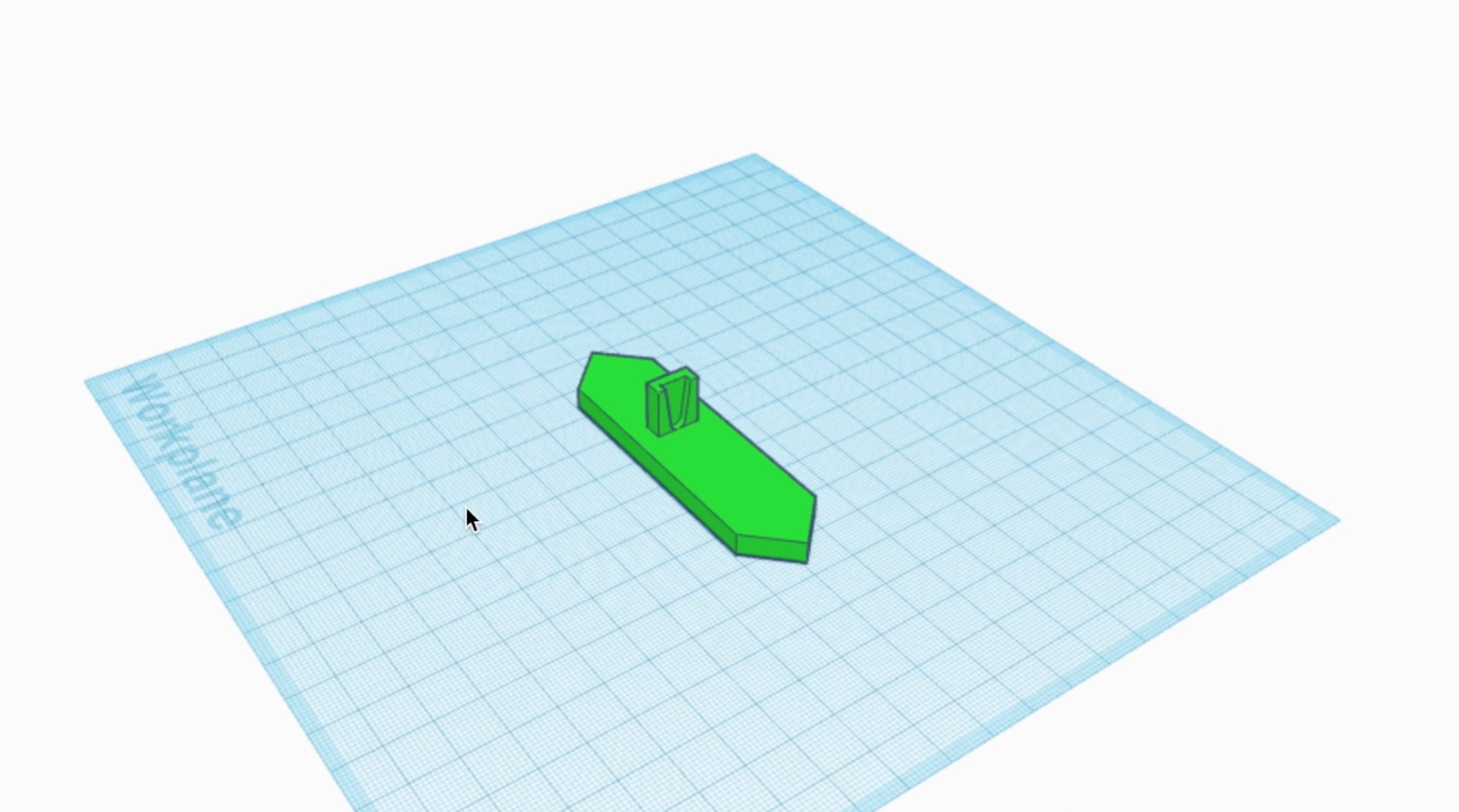
You’ll also need to glue the small 3D printed spacer blocks to the bottom of each servo as well, these help the servo to stand upright when you glue them onto the back board.
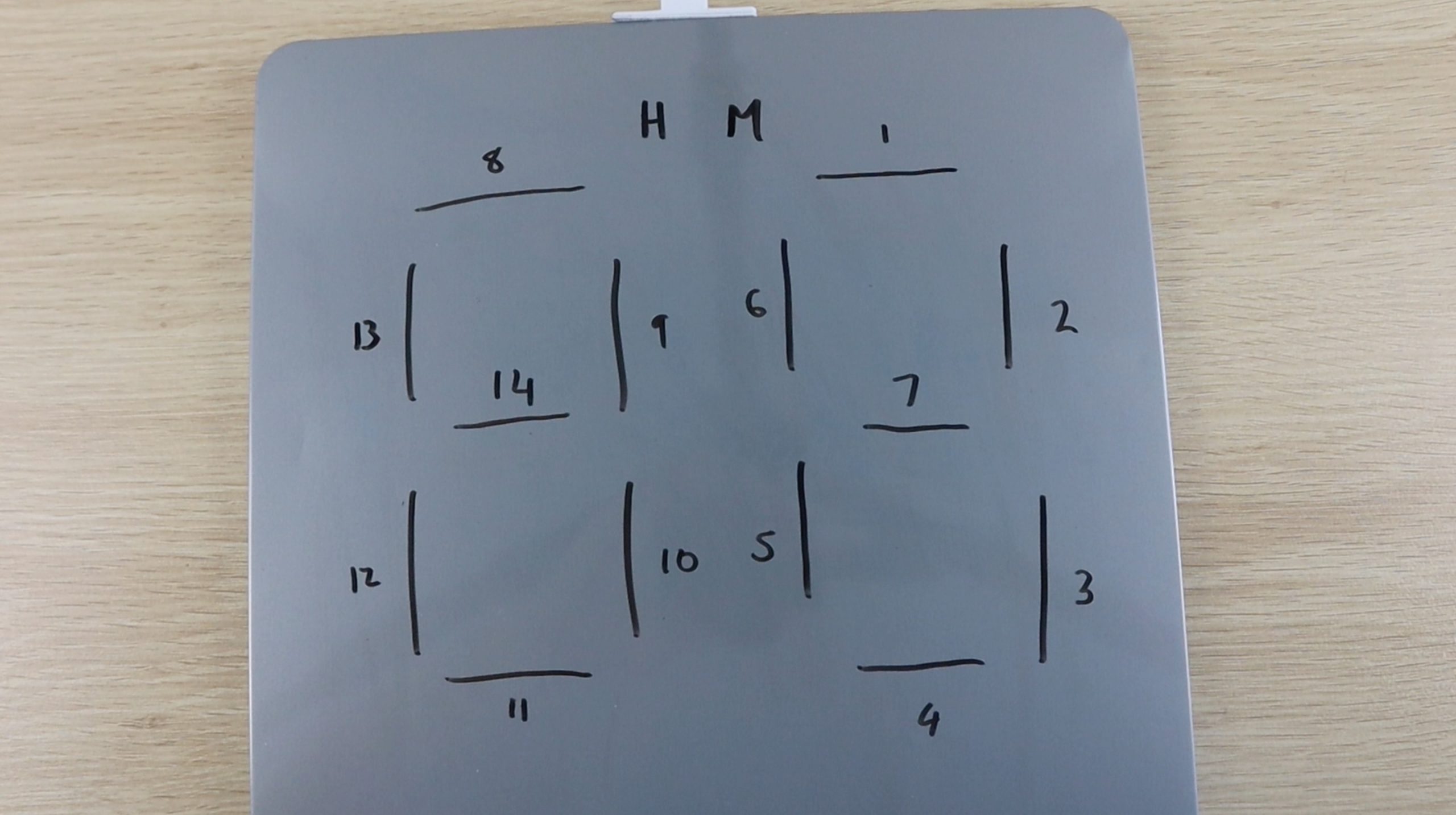
I numbered each segment to keep track of them in the code. I started with the top segment in the units digit being 1 and worked around to the tens digit for all fourteen segments. They are connected to each driver board in this order as well, although the driver board numbering starts from zero. I duplicated this numbering for each of the hour and minute boards. If you’re struggling to keep track of each servo, write these numbers onto the leads as well.
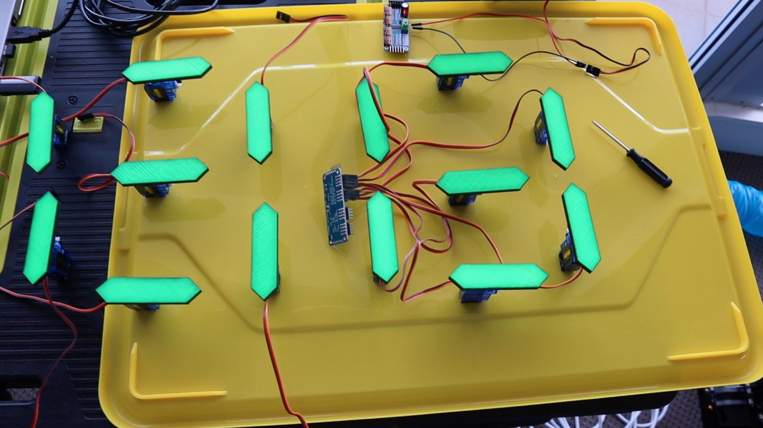
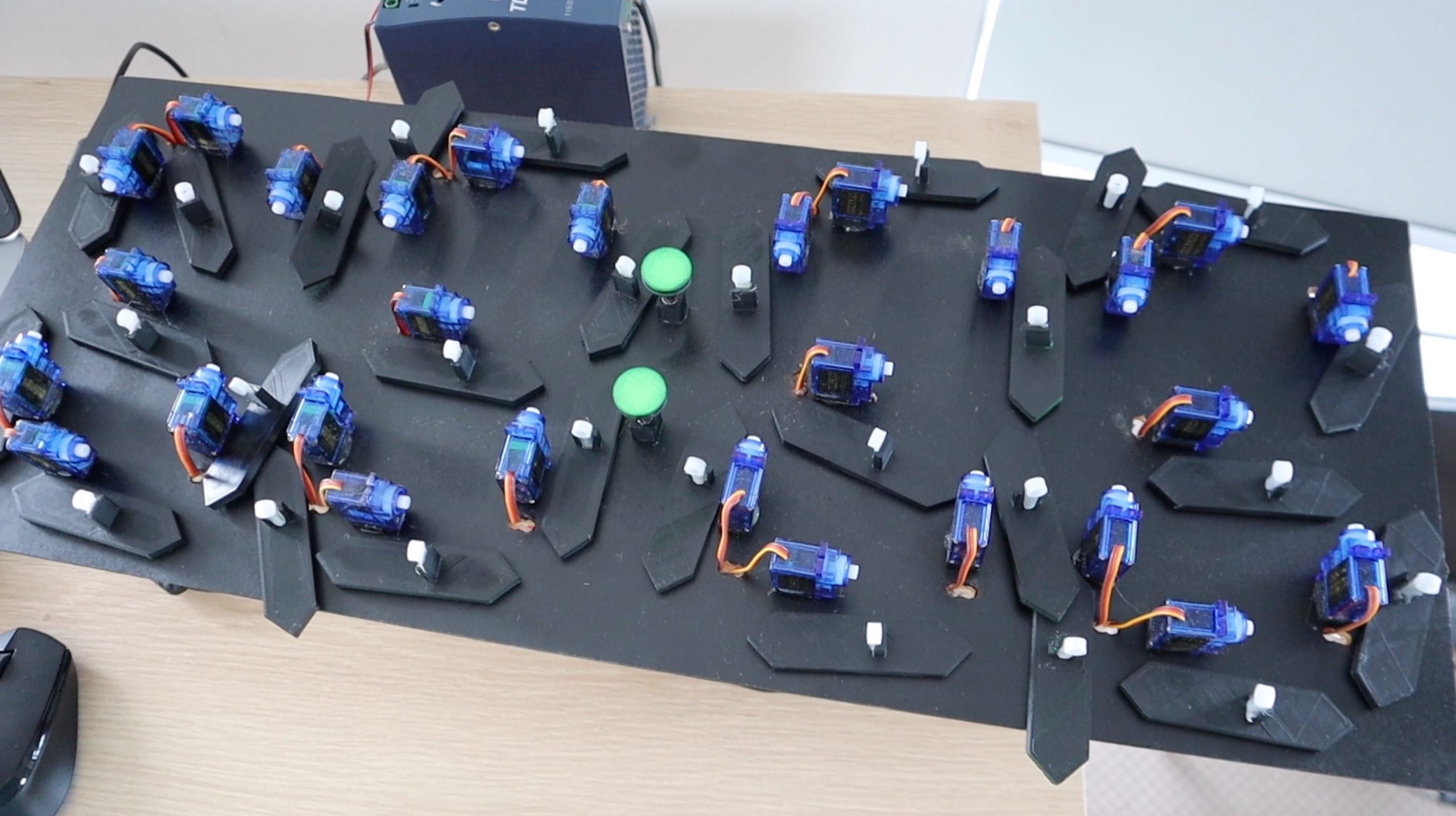
Before gluing the digits onto the back board, I laid them out on a flat surface to test them. This allowed them to move without the fear of them moving in the wrong direction or too far and bumping into each other, which may damage the segments or strip the gears on the servos.
Once I was happy with the movement of the digits, I got to work on the board.
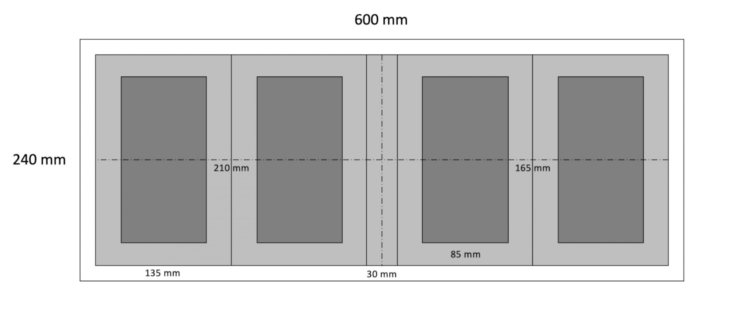
You’ll need a back board which is at least 600mm (24″) long by 240mm (10″) high. The light grey larger boxes are the areas in which the segments move when they move out of the way, these need to be at least 210mm (8 1/4″) by 135mm (5 1/3″) so that adjacent segments don’t touch when they both move outwards to their off positions. The inner darker rectangles are the centre lines for the 6 servos which make up the outside of each digit. Lastly, leave 30mm between the inner digits for the dots.
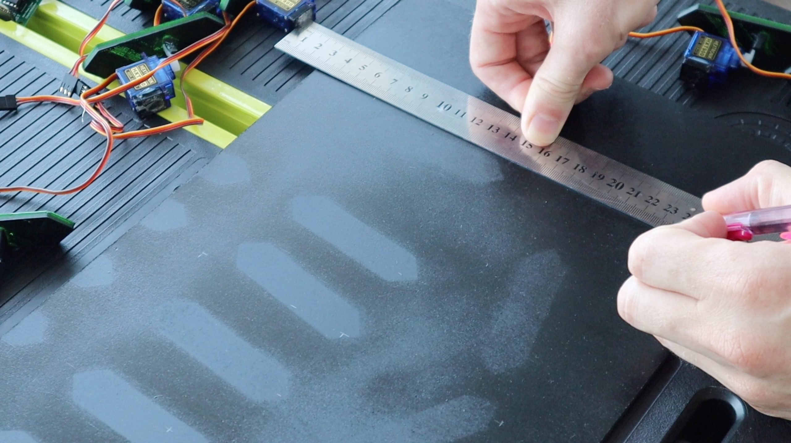
Measure and cut the back board from a piece of 3mm MDF and spray it black as well.
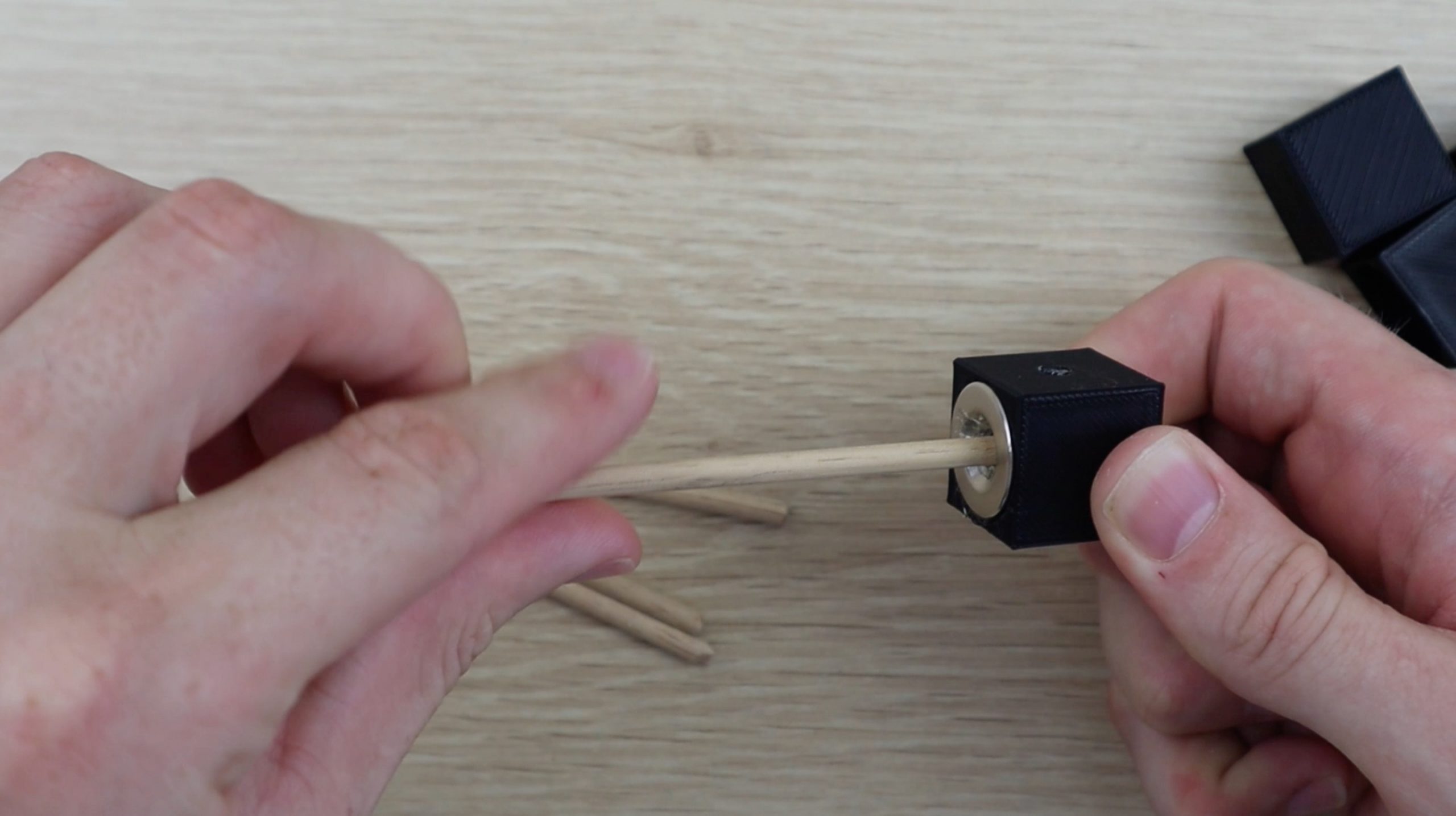
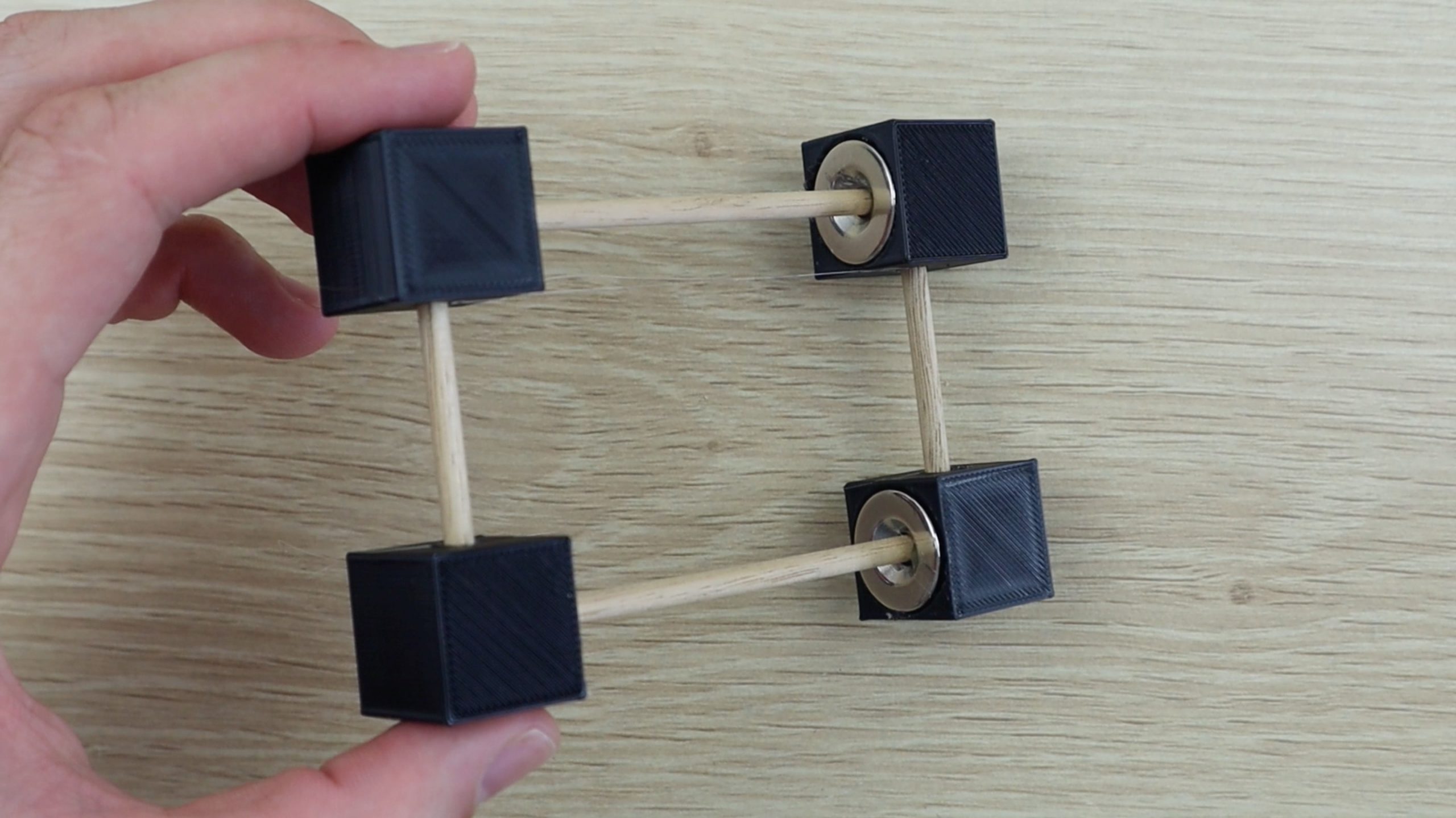
Mark the segment positions on the back board as per the diagram and then start gluing them in place. The dots are supported on their bases using short sections of 4mm dowel or kebab sticks. Measure and cut the sticks such that the dots are at the same level as the segments once they are glued onto the back board.
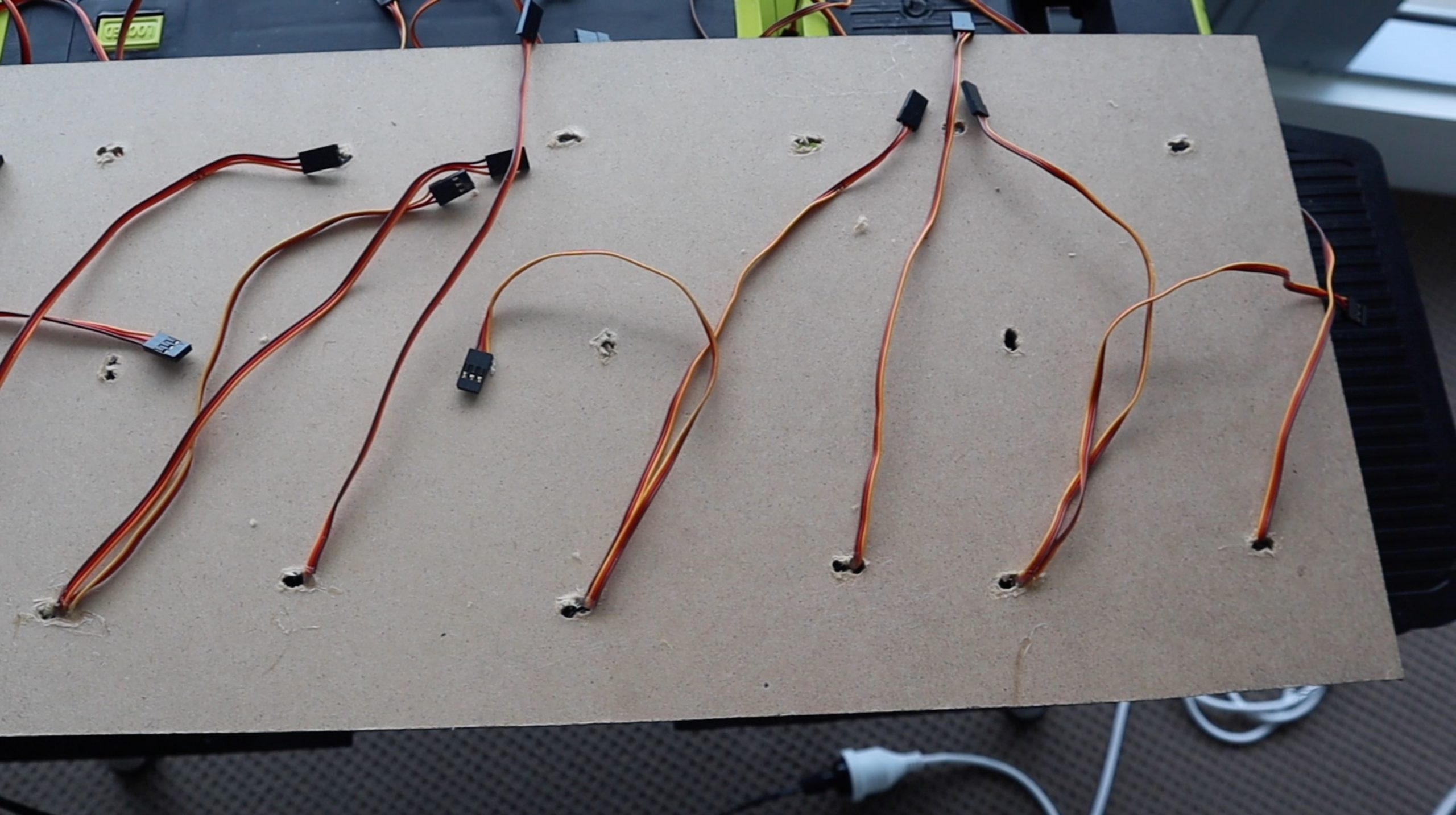
Once the digits are done, you’ll need to hide the wiring. Drill holes through to the back of the board near each servo to feed the servo wires through, this is when it helps to have numbered the leads beforehand. Put a small drop of glue onto each to keep them in place.
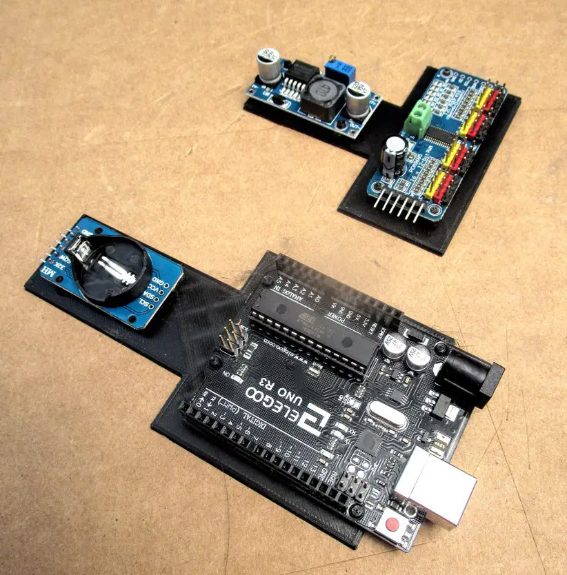
Stick the four electronics boards onto the back of the clock using double sided tape. You could also mount them with screws, just make sure that the screws don’t go all the way through the MDF to the other side.
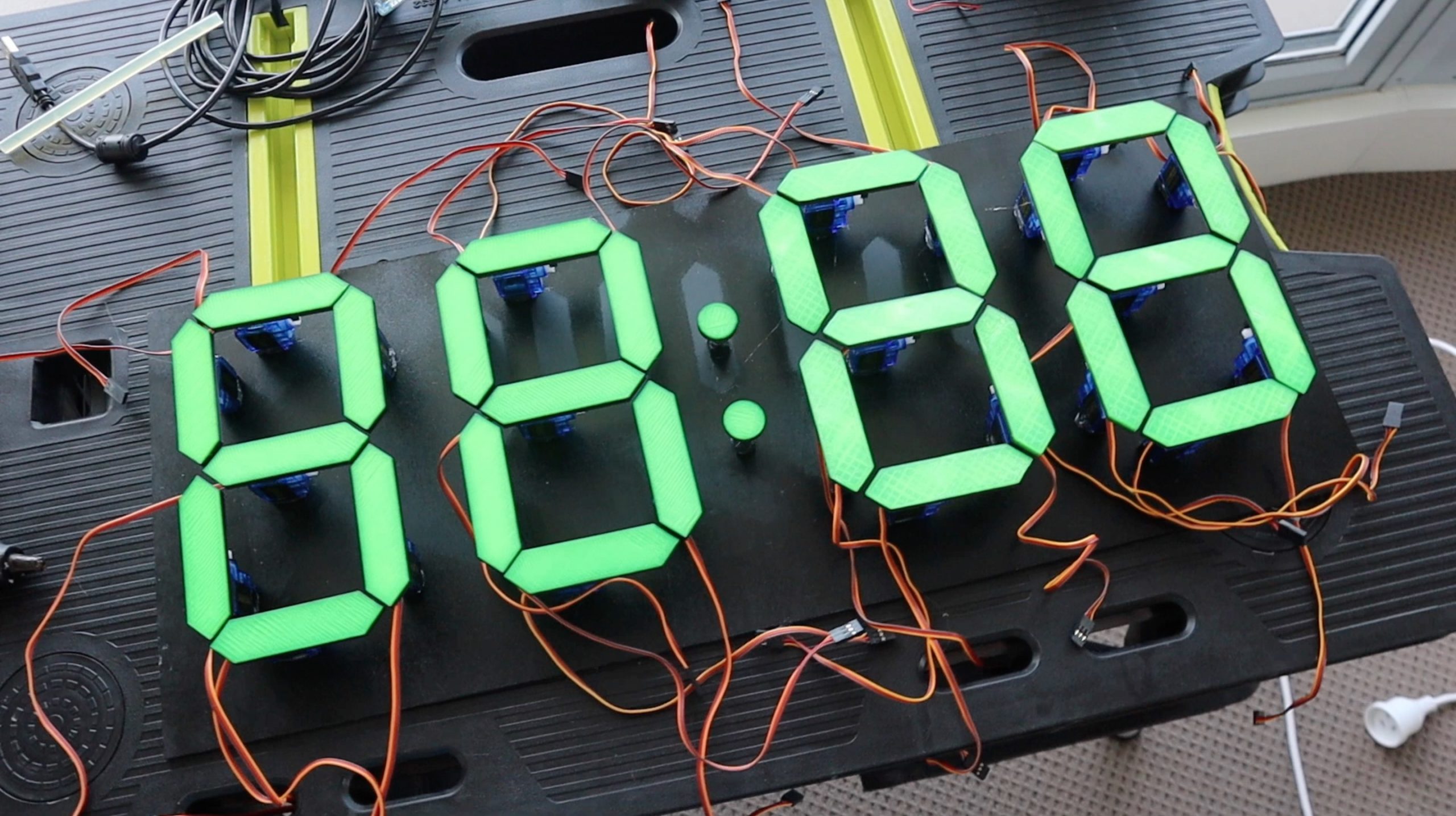
I removed the arms from the servos before loading the final version of the software so that I could make small adjustments to the upright positions without worrying about them hitting each other. It’s a good idea to remove the arms from your servos and keep them off until you’ve powered your board up at least once and got the servos all in their On positions, 88:88 displayed. This way you can put them back into place without worrying about them moving and bumping into each other.
Uploading The Sketch
Now that you’re done building your clock, lets have a look at the code:
//Michael Klements
//The DIY Life
//8 February 2020

#include <virtuabotixRTC.h>               //Include library for clock module
#include <Adafruit_PWMServoDriver.h>      //Include library for servo driver

Adafruit_PWMServoDriver pwmH = Adafruit_PWMServoDriver(0x40);    //Create an object of Hour driver
Adafruit_PWMServoDriver pwmM = Adafruit_PWMServoDriver(0x41);    //Create an object of Minute driver (A0 Address Jumper)

int servoFrequency = 50;      //Set servo operating frequency

int segmentHOn[14] = {385,375,385,375,382,375,354,367,375,385,375,368,371,375};   //On positions for each Hour servo
int segmentMOn[14] = {382,395,378,315,375,340,345,380,385,365,290,365,315,365};   //On positions for each Minute servo
int segmentHOff[14] = {200,200,550,480,200,520,200,200,200,480,550,200,515,200};    //Off positions for each Hour servo
int segmentMOff[14] = {200,200,550,440,200,480,200,200,200,550,450,200,430,200};    //Off positions for each Minute servo
int digits[10][7] = {{1,1,1,1,1,1,0},{0,1,1,0,0,0,0},{1,1,0,1,1,0,1},{1,1,1,1,0,0,1},{0,1,1,0,0,1,1},
                     {1,0,1,1,0,1,1},{1,0,1,1,1,1,1},{1,1,1,0,0,0,0},{1,1,1,1,1,1,1},{1,1,1,1,0,1,1}};    //Position values for each digit

virtuabotixRTC myRTC(6, 7, 8);    //Create a clock object attached to pins 6, 7, 8 - CLK, DAT, RST
int hourTens = 0;                 //Create variables to store each 7 segment display numeral
int hourUnits = 0;
int minuteTens = 0;
int minuteUnits = 0;

int prevHourTens = 8;           //Create variables to store the previous numeral displayed on each
int prevHourUnits = 8;          //This is required to move the segments adjacent to the middle ones out of the way when they move
int prevMinuteTens = 8;
int prevMinuteUnits = 8;

int midOffset = 100;            //Amount by which adjacent segments to the middle move away when required

void setup()
{
  pwmH.begin();                             //Start each board
  pwmM.begin();
  pwmH.setOscillatorFrequency(27000000);    //Set the PWM oscillator frequency, used for fine calibration
  pwmM.setOscillatorFrequency(27000000);
  pwmH.setPWMFreq(servoFrequency);          //Set the servo operating frequency
  pwmM.setPWMFreq(servoFrequency);
  //myRTC.setDS1302Time(00, 10, 16, 5, 8, 4, 2020);        //Only required once to reset the clock time
  for(int i=0 ; i<=13 ; i++)    //Set all of the servos to on or up (88:88 displayed)
  {
    pwmH.setPWM(i, 0, segmentHOn[i]);
    delay(10);
    pwmM.setPWM(i, 0, segmentMOn[i]);
    delay(10);
  }
  delay(2000);
}

void loop()
{
  myRTC.updateTime();                 //Update the time
  int temp = myRTC.hours;             //Get the hours and save to variable temp
  hourTens = temp / 10;               //Split hours into two digits, tens and units
  hourUnits = temp % 10;
  temp = myRTC.minutes;               //Get the minutes and save to variable temp
  minuteTens = temp / 10;             //Split minutes into two digits, tens and units
  minuteUnits = temp % 10;

  if(minuteUnits != prevMinuteUnits)  //If minute units has changed, update display
    updateDisplay();

  prevHourTens = hourTens;            //Update previous displayed numerals
  prevHourUnits = hourUnits;
  prevMinuteTens = minuteTens;
  prevMinuteUnits = minuteUnits;

  delay(500);
}

void updateDisplay ()                               //Function to update the displayed time
{
  updateMid();                                      //Move the segments out of the way of the middle segment and then move the middle segments
  for (int i=0 ; i<=5 ; i++)                        //Move the remaining segments
  {
    if(digits[hourTens][i]==1)                      //Update the hour tens
      pwmH.setPWM(i+7, 0, segmentHOn[i+7]);
    else
      pwmH.setPWM(i+7, 0, segmentHOff[i+7]);
    delay(10);
    if(digits[hourUnits][i]==1)                     //Update the hour units
      pwmH.setPWM(i, 0, segmentHOn[i]);
    else
      pwmH.setPWM(i, 0, segmentHOff[i]);
    delay(10);
    if(digits[minuteTens][i]==1)                    //Update the minute tens
      pwmM.setPWM(i+7, 0, segmentMOn[i+7]);
    else
      pwmM.setPWM(i+7, 0, segmentMOff[i+7]);
    delay(10);
    if(digits[minuteUnits][i]==1)                   //Update the minute units
      pwmM.setPWM(i, 0, segmentMOn[i]);
    else
      pwmM.setPWM(i, 0, segmentMOff[i]);
    delay(10);
  }
}

void updateMid()                                              //Function to move the middle segements and adjacent ones out of the way
{
  if(digits[minuteUnits][6]!=digits[prevMinuteUnits][6])      //Move adjacent segments for Minute units
  {
    if(digits[prevMinuteUnits][1]==1)
      pwmM.setPWM(1, 0, segmentMOn[1]-midOffset);
    if(digits[prevMinuteUnits][6]==1)
      pwmM.setPWM(5, 0, segmentMOn[5]+midOffset);
  }
  delay(100);                                                 //Delay allows adjacent segments to move before moving middle
  if(digits[minuteUnits][6]==1)                               //Move Minute units middle segment if required
    pwmM.setPWM(6, 0, segmentMOn[6]);
  else
    pwmM.setPWM(6, 0, segmentMOff[6]);
  if(digits[minuteTens][6]!=digits[prevMinuteTens][6])        //Move adjacent segments for Minute tens
  {
    if(digits[prevMinuteTens][1]==1)
      pwmM.setPWM(8, 0, segmentMOn[8]-midOffset);
    if(digits[prevMinuteTens][6]==1)
      pwmM.setPWM(12, 0, segmentMOn[12]+midOffset);
  }
  delay(100);                                                 //Delay allows adjacent segments to move before moving middle
  if(digits[minuteTens][6]==1)                                //Move Minute tens middle segment if required
    pwmM.setPWM(13, 0, segmentMOn[13]);
  else
    pwmM.setPWM(13, 0, segmentMOff[13]);
  if(digits[hourUnits][6]!=digits[prevHourUnits][6])          //Move adjacent segments for Hour units
  {
    if(digits[prevHourUnits][1]==1)
      pwmH.setPWM(1, 0, segmentHOn[1]-midOffset);
    if(digits[prevHourUnits][6]==1)
      pwmH.setPWM(5, 0, segmentHOn[5]+midOffset);
  }
  delay(100);                                                 //Delay allows adjacent segments to move before moving middle
  if(digits[hourUnits][6]==1)                                 //Move Hour units middle segment if required
    pwmH.setPWM(6, 0, segmentHOn[6]);
  else
    pwmH.setPWM(6, 0, segmentHOff[6]);
  if(digits[hourTens][6]!=digits[prevHourTens][6])            //Move adjacent segments for Hour tens
  {
    if(digits[prevHourTens][1]==1)
      pwmH.setPWM(8, 0, segmentHOn[8]-midOffset);
    if(digits[prevHourTens][6]==1)
      pwmH.setPWM(12, 0, segmentHOn[12]+midOffset);
  }
  delay(100);                                                 //Delay allows adjacent segments to move before moving middle
  if(digits[hourTens][6]==1)                                  //Move Hour tens middle segment if required
    pwmH.setPWM(13, 0, segmentHOn[13]);
  else
    pwmH.setPWM(13, 0, segmentHOff[13]);
}
Download the sketch – Mechanical 7 Segment Clock
I have created a GitHub repository for this code to allow others to share their changes and improvements.
We start by importing two libraries, <virtuabotixRTC.h> for the clock module and <Adafruit_PWMServoDriver.h> for the servo drivers. The Adafruit library can be downloaded and installed directly through the library manager in the IDE.
We then create an object for each of the servo drivers, one for the two hour digits and one for the two minute digits. Note that we’ve changed the address in the second to match the jumper we’ve soldered onto the board.
We then have four arrays to store the on and off positions for each servo, this allows you to fine tune the travel limits so that the digits are all straight and don’t over or under travel when they move to the off position. You’ll need to adjust these values for each of your servos before using your clock. Adjust the on positions so that the segments are completely upright and as horizontal as possible and then adjust the off positions so that the segments are turned at least 90 degrees but are not over travelling.
We then have an array to store the segment positions for each digit from 0 to 9. There are ten digits and seven segments for each digit, where a 1 represents ON or upright and a 0 represents OFF or turned 90 degrees.
We then assign the clock pins and create variables for each digit, hour tens and units and minute tens and units. We’ll need the time split into these individual digits so that we know what each 7 segment display should be showing.
We also need to know what the previously displayed digit was so that we know whether the middle segment is going to be moving, and if so, we may need to move the two adjacent segments out of the way a little so that it can pass by without hitting them.
The variable midOffset defines by how much these adjacent segments should move out of the way.
We then start with the setup function. Here we start each of the PWM servo boards, set their oscillator frequency and our servo frequency.
We then have a line to update the clock time, which is only needed once to set the time on your clock and can then be removed or commented out. You’ll need to set the time to an upcoming time and then time your upload so that the time update is run at the same time as that time is reached in reality so that your clock module is correctly set. This sounds more complicated than it actually is.
Finally, we run through a loop which sets each servo to it’s on position so that 8 8 : 8 8 is displayed on the clock. This ensures that we have a known starting position for each servo and where possible, you should try and start your clock with the segments as close to these positions as possible in order to avoid having them bump into each other, particularly with the middle segments.
We then move on to the main loop where we get the updated time from the real time clock module, then split the hour and minutes into their tens and units. We then check to see if the time has changed since the last cycle and only if the time has changed, do we need to update the display.
Once the display is updated, then we update the previously displayed variables to record the changes.
Now let’s have a look at the update display function. We start by updating the middle segments. We do this so that we are able to move the adjacent segments out of the way if the middle segments need to move. We then move all of the middle segments and then finally move the remaining segments so that they’re moved back into place if the previous step moved them out of the way for the middle segment. In summary, we move the adjacent segments out of the way, then move the middle segment and then update the other 6 segments, this is done for all four digits.
There is an if statement for each digit which essentially looks up the required segment positions from the array and then moves them on or off accordingly. The delays just aid with stability in the code.
The update mid function is probably the most complex portion of the code, although there is a lot of repetition for each of the four digits. This function looks at whether the middle segment of the digit needs to move. If it does, it then looks at whether either of the adjacent digits are going to be in the way of this movement and if they are, it then moves them out of the way before moving the middle segment. The delays here are to allow the adjacent segments to move out of the way before moving the middle segment.
Thats the code, now upload it to your Arduino and see what it looks like.
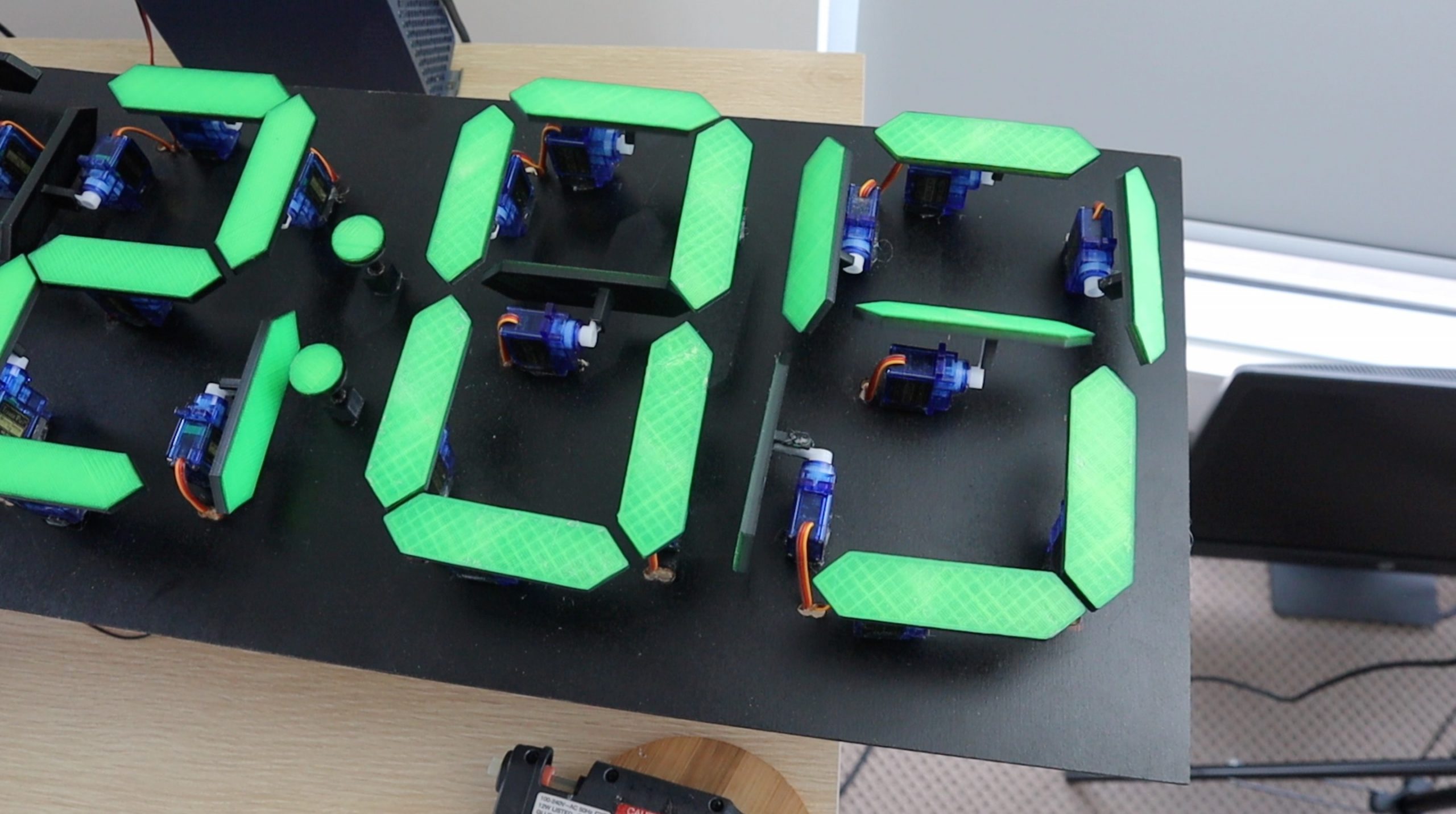
Using Your Mechanical 7 Segment Display Clock
The segments jitter slightly when they are initialised and then move to display the current time. As mentioned previously, you should always try to power your clock on with the segments in the 8 8 : 8 8 positions so that they don’t bump into each other when initialising. This is usually only an issue when the digits 1 or 7 have been displayed and power is lost as the middle segment then needs to move back into place and the code doesn’t know that the adjacent sections are in the way.
It takes a bit of patience in the beginning to get each segment’s travel limits set up correctly so that the segment is upright when on and moved far enough when off so that the top is no longer visible. Most of my segments required adjustment and there were quite a few cases of servo arms popping off and servo’s over travelling during this setup process. It can be quite frustrating to get right, but once you’re done, you’re left with a great looking clock with a unique twist on a 7 segment display. Time spent setting your clock up will result in a much better looking end product.
I’ve left mine plugged in with the 12V power adaptor. The real time clock has a battery backup, so if the power goes down then the clock should automatically reset itself and resume displaying the correct time when the power returns.
I hope you enjoy building your own mechanical 7 segment display clock. Let me know how it goes for you, or any tips and suggestions in the comments section below.
Community Builds
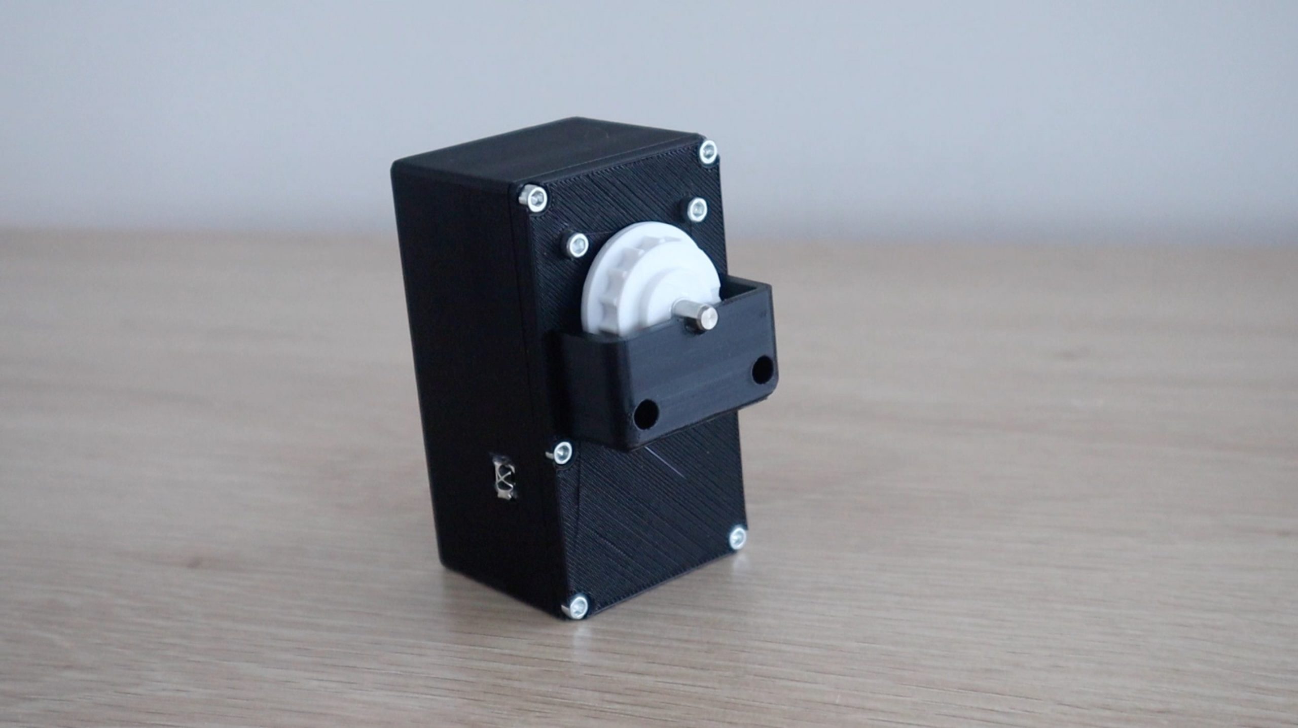
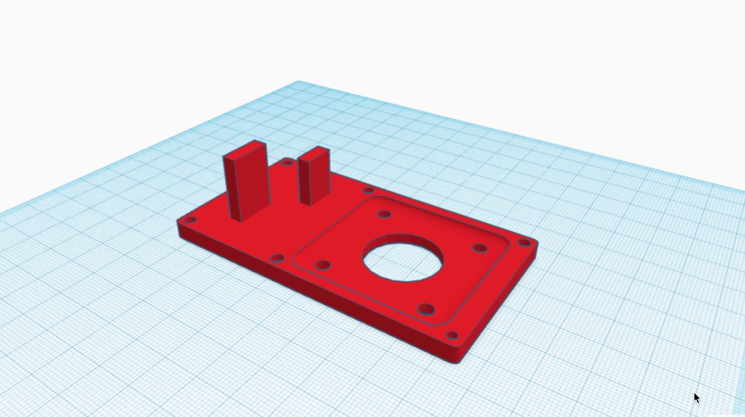
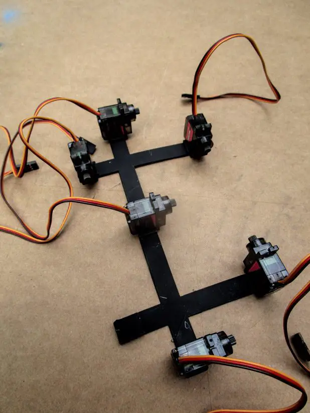
Tony Johnson from Ontario, Canada has made some neat additions to the clock by designing a 3D printed sub-base in Sketchup to easily position the servos for each digit as well as the center dots.
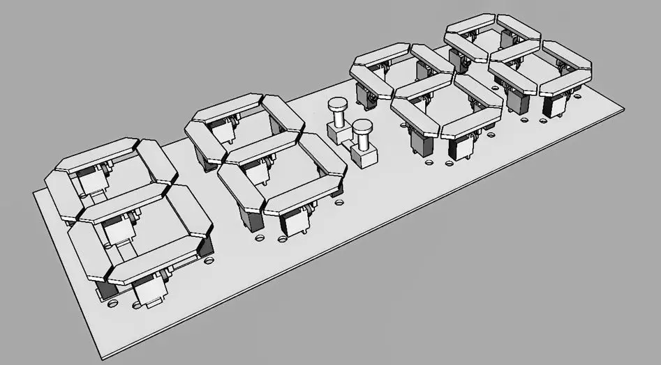
He also printed holders for the electronics. Tony initially used an LM2596 voltage converter to power each of the PWM driver boards but said that they failed after only a few hours of operation. They may have been damaged during setup when the servos are more likely to overtravel and stall, but it’s worth keeping in mind if you’re looking at alternatives to power your clock. He has since replaced these boards with a 5V, 10A transformer which has been working well.
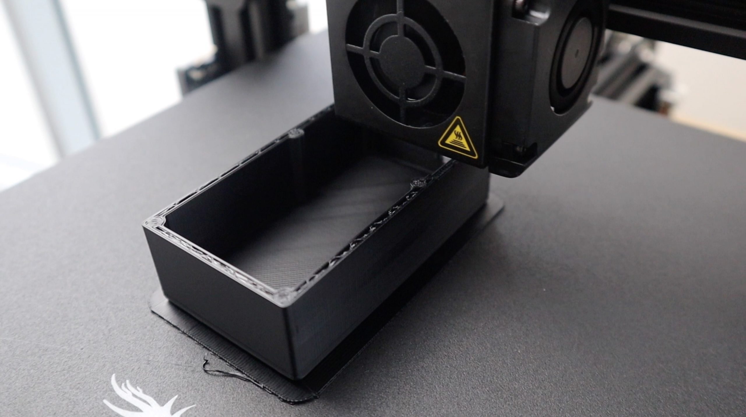
He also added some covers to blackout the servos and hide them a bit better.
His final clock has come out really well: