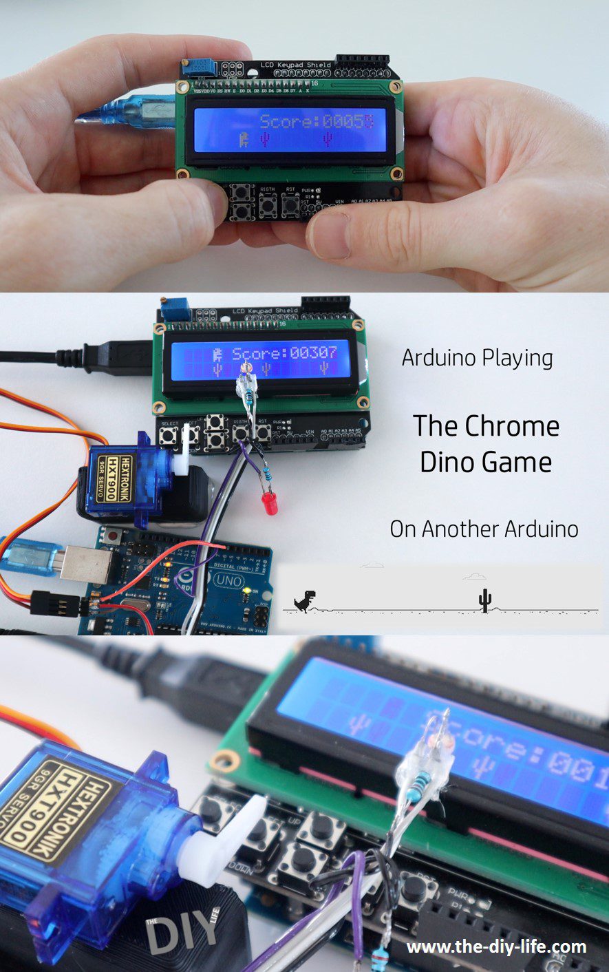
You may have seen people using an Arduino to automate playing the Chrome Dino Game in their browser, I thought we could take it a bit further and see if we could get one Arduino to play the Chrome Dino Game on another Arduino.
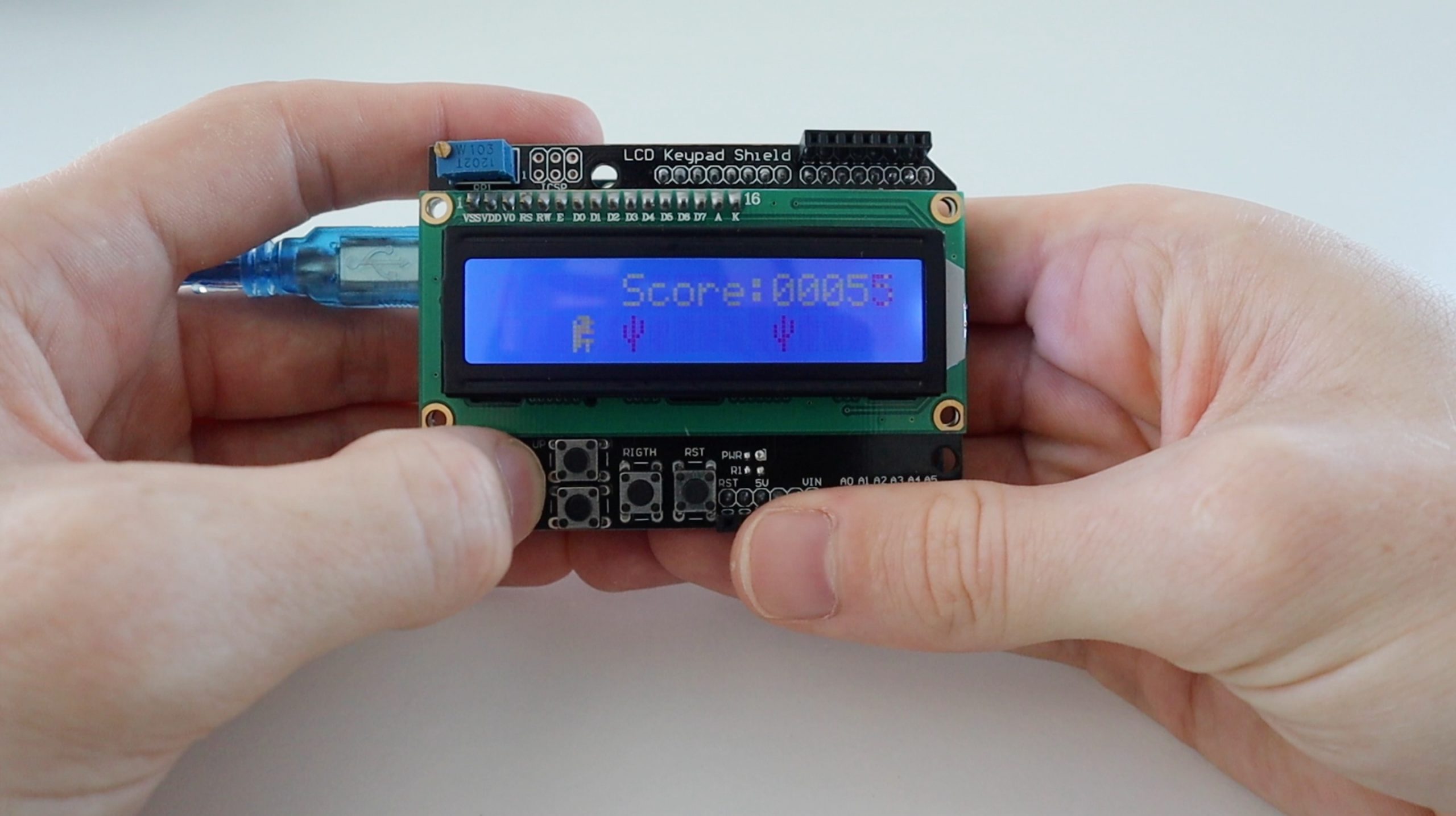
I’ve previously set up an Arduino to run a simple version of the game, which produces a continuous stream of randomly spaced cactuses at an increasing speed, and closer together. The game is really easy to get running and only requires an Arduino Uno and an LCD keypad shield. A single button on the keypad shield is then used to make the dinosaur jump over each cactus until the player messes up and hits one. The score is kept based on how long you’re able to avoid running into a cactus.
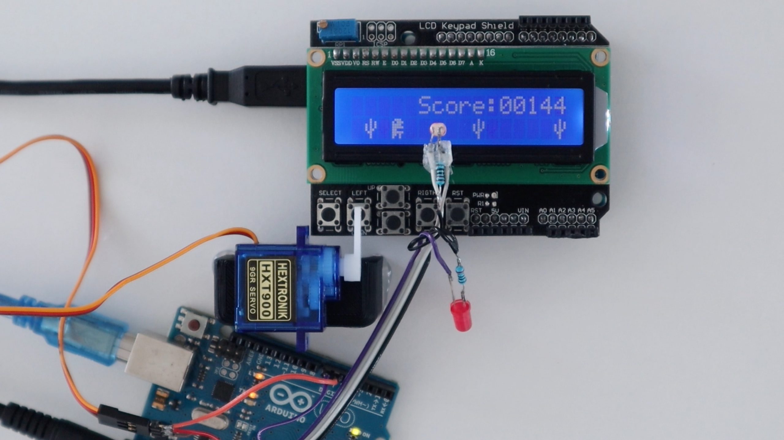
Once I had the game running on one Arduino, I set up a second one, which uses an LDR to sense each cactus and then moves a servo to press the button on the other Arduino to make the dinosaur jump over each cactus.
Here’s a video of the build and the one Arduino playing the Chrome Dino Game on the other:
We’ll first have a look at running the dino game on an Arduino and then set up a second to play the game on the first. The code would be the same to set the second Arduino up to play on your computer’s browser as well, you’d just need to stick the LDR to the display.
What You Need For This Project
For The Dino Game
For The Dino Game Player
- Arduino Uno – Buy Here
- Micro Servo – Buy Here
- LDR / Photoresistor – Buy Here
- LED – Buy Here
- Resistors – Buy Here
- Ribbon Cable – Buy Here
- Male Pin Headers – Buy Here
- Power Supply – Buy Here
How To Load The Chrome Dino Game
Let me start out by saying – I didn’t code the dino game. It’s a version I found on Hackster.io which was the least complicated layout and ran the smoothest. One downside is that it’s written in AVR C code, so it looks a little different to the generic Arduino language but you should still be able to figure a lot of it out, I’ve also expanded on the description of the game and explained how you can change a few things around in another post – How to Play the Chrome Dino Game onto an Arduino.
Here’s a general overview of the game:
- You push a button on the keypad shield to make the dinosaur jump over each cactus.
- The game speed up the longer you play it.
- Cactuses are initially separated by a minimum of 5 spaces and this goes down to 4 as the game progresses.
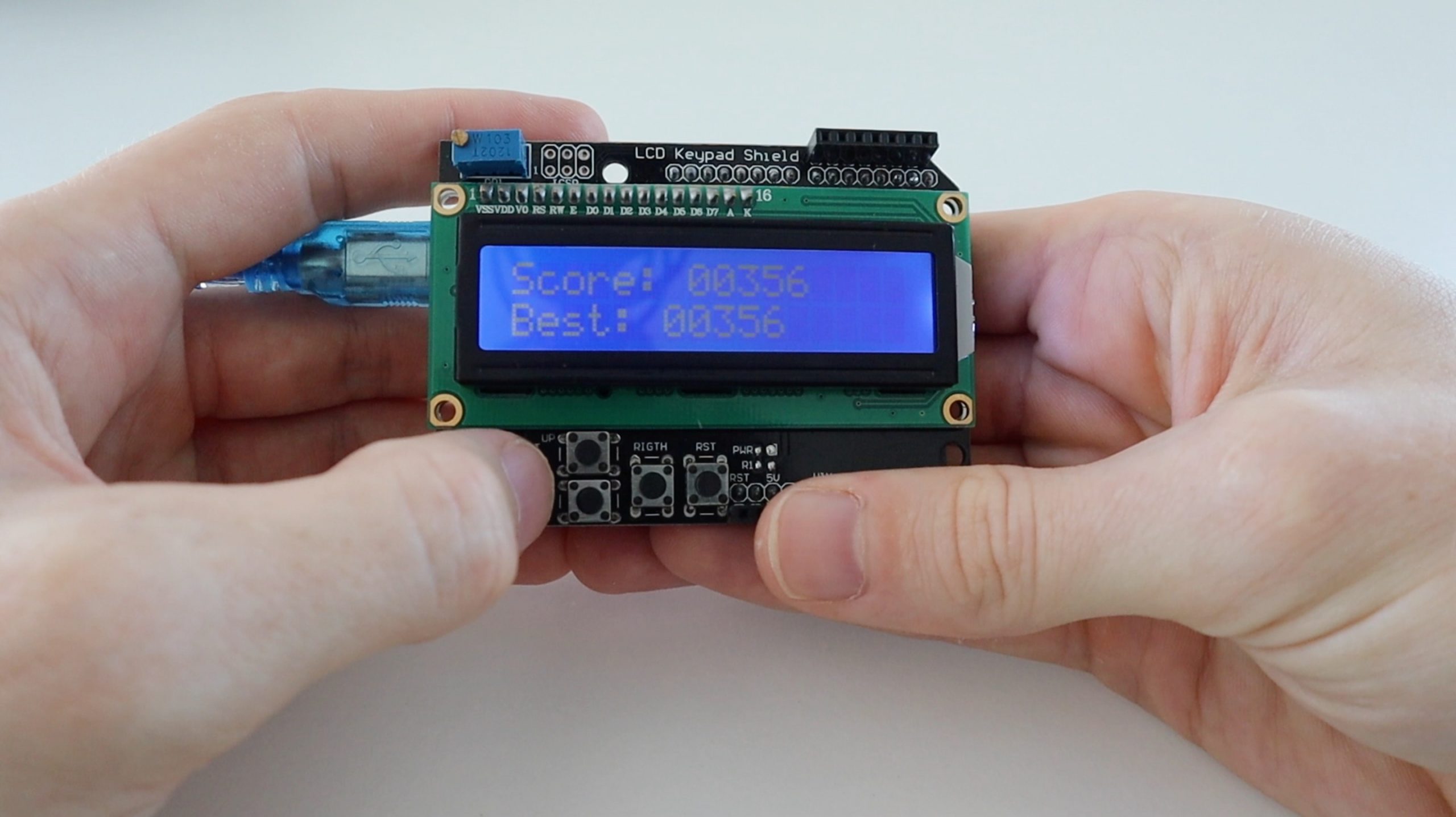
- The current score is displayed throughout the game and is joined by the high score at the end of the game.
- Cheating by holding down the button or continuously pressing the button is prevented.
I have made a couple of changes to the original version of the code for the timing, cactus spacing and the text layouts to better accommodate the sensor.
Here is the code:
//From Hackster.io
//By BRZI

#include <avr/io.h>
#define  F_CPU 16000000UL //Our CPU speed (16MHz)
#include <util/delay.h> //Libraries for delay and interrupt utilities
#include <avr/interrupt.h>
#define command 0 //explained in dispSend() function
#define write 1

uint8_t upperBuff[16] , downerBuff[16], overMsgUpper[] = "Score:  ", overMsgDowner[] = "Best:   ", scoremsg[] = "Score:" , din[] = {0x0E, 0x17, 0x1E, 0x1F, 0x18, 0x1F, 0x1A, 0x12}, cact[] = {0x04, 0x05, 0x15, 0x15, 0x16, 0x0C, 0x04, 0x04};
        //Buffers for line one and two. Message to display after lost game.                     //Score text during game. //Dinosaur and cactus bitmaps
uint8_t canup = 1, longhold = 0, distance = 6, speed = 200, isup = 0, dontprint = 0; //All of these are explained further
uint16_t aVal = 0, score = 1, bestscore = 0;
int i;

void dispInit();
void dispWrite(uint8_t bits);
void dispSend(uint8_t bits, uint8_t act);
void dispSetLine(uint8_t line);
void dispClear();
void dispHome();
void dispPrintChar(uint8_t chr[], uint8_t size);
uint16_t aRead();

int main(void)
{
  for(i = 0; i < 17; i++) downerBuff[i] = ' '; //Initialize upper and downward buffer
  for(i = 0; i < 17; i++) upperBuff[i] = ' ';

  dispInit(); //Initialize the display

  TCCR1B |= (1 << WGM12) | (1 << CS11); //Set Timer1 to compare to OCR1A and prescaler of 8
  OCR1AH = (500 >> 8); //This equals to 2000Hz or 500us timing, look for TIMER1_COMPA_vect down below
  OCR1AL = 500;
  TIMSK1 |= (1 << OCIE1A); //Enable Timer1 CompA ISR
  sei(); //Enable global interrupt


  ADMUX = (1 << REFS0); //Set AREF to VCC
  ADCSRA = (1 << ADPS2) | (1 << ADPS1) | (1 << ADPS0) | (1 << ADEN); //set ADC prescaler to 128 and enable ADC (defaulted to free running mode)

  while (1) {

    ADMUX |= (1 << MUX2) | (1 << MUX0); //Set pin from ADMUX to ADC5 (floating)
    srand(aRead()); //Use it as a random seed
    ADMUX &= ~(1 << MUX2) & ~(1 << MUX0); //Revert back to ADC0 to read the button value

    if(aRead() > 900) longhold = 0; //Reads if Up button has been released to prevent cheating. The value is so low because if you hold your fingers beneath one of the buttons the voltage would drop, this prevents the dinosaur from locking up

    for(i = 0; i < 16; i++) downerBuff[i] = downerBuff[i + 1]; //Shifts everything in downward buffer by one place to the left
     if((rand() % 100) > (rand() % 100) && !dontprint){ //This portion decides if it should put a cactus or a blank spot, dontprint is used to prevent cactus grouping
      downerBuff[15] = 0x01; //0x01 represents the cactus (we added cactus and dinosaur to CGRAM when we initialized the display)
      dontprint = 1; //This part acts both as a boolean and a counter to ensure cactus separation
     }
     else downerBuff[15] = ' ';
     char lastchar = downerBuff[3]; //We remember the whats initially added to the downward buffer before replacing it with the dinosaur
     if(!isup){ //If din should be placed down
      downerBuff[3] = 0x00; //Place it down
      dispSetLine(2);
      dispPrintChar(downerBuff, sizeof(downerBuff)); //Draw it
      downerBuff[3] = lastchar; //Place back previous thing to the buffer
      canup = 1;  //This flag is used to disable dinosaur from getting up before it was drawn down, in this case he can go up
    } else { //If din should be placed up
      upperBuff[3] = 0x00; //Place it up in upper buff
      dispSetLine(1);
      dispPrintChar(upperBuff, sizeof(upperBuff));
      dispSetLine(2);
      dispPrintChar(downerBuff, sizeof(downerBuff)); //Draw it
      canup = 0; //In this case he wont go up until rendered on line 2
    }

    if(dontprint) dontprint++;
    if(dontprint > distance) dontprint = 0; //This is the part that ensures cactus separation, it will keep the cactus 3-5 spaces apart minimally (depends on the game progress)

    if(isup) isup++; //This part makes sure din is on upper side for 3 loops after he was initially drawn there
    if(isup > 4){
     upperBuff[3] = ' ';
     dispSetLine(1);
     dispPrintChar(upperBuff, sizeof(upperBuff));
     isup = 0;
    }
    for(i = 0; i < sizeof(scoremsg); i++) upperBuff[i + 5] = scoremsg[i]; //This part prints the current score during the game
    uint8_t cnt = 11;
    for(i = 10000; i > 0; i /= 10){
      upperBuff[cnt] = ((score / i) % 10) + '0';
      cnt++;
      dispSetLine(1);
      dispPrintChar(upperBuff, sizeof(upperBuff));
    }

    score++; //Increment the score once on loop
    if(score > bestscore) bestscore = score; //Remember best score

    if(lastchar == 0x01 && !isup){ //Check if the dinosaur is downward and hit a cactus
      dispClear(); //Clear the display and buffers
      for(i = 0; i < 17; i++) downerBuff[i] = ' ';
      for(i = 0; i < 17; i++) upperBuff[i] = ' ';
      uint8_t cnt;

      dispSetLine(1);
      for(i = 0; i < sizeof(overMsgUpper); i++) upperBuff[i] = overMsgUpper[i]; //Display worst and best score
      cnt = sizeof(overMsgUpper) - 1;
      for(i = 10000; i > 0; i /= 10){
        upperBuff[cnt] = ((score / i) % 10) + '0';
        cnt++;
      }
      dispPrintChar(upperBuff, sizeof(upperBuff));

      dispSetLine(2);
      for(i = 0; i < sizeof(overMsgDowner); i++) downerBuff[i] = overMsgDowner[i];
      cnt = sizeof(overMsgDowner) - 1;
      for(i = 10000; i > 0; i /= 10){
        downerBuff[cnt] = ((bestscore / i) % 10) + '0';
        cnt++;
      }
      dispPrintChar(downerBuff, sizeof(downerBuff));

      while(1){ //Wait for select button to be pressed
        aVal = aRead();
        if(aVal > 635 && aVal < 645){ //After that clear all the variables
          for(i = 0; i < 17; i++) downerBuff[i] = ' ';
          dispSetLine(1);
          dispPrintChar(downerBuff, sizeof(downerBuff));
          for(i = 0; i < 17; i++) upperBuff[i] = ' ';
          dispSetLine(2);
          dispPrintChar(upperBuff, sizeof(upperBuff));
          dontprint = 0;
          isup = 0;
          score = 1;
          speed = 200;
          longhold = 0;
          distance = 6;
          canup = 1;
          break;
             }
      }

    }
    if(score % 5 == 0) speed -=1; //If score is divisible by 5 make game faster by -2ms
    if(speed < 120) speed = 120; //Minimal time in ms (+ ~2ms) that the loop will be halted for (limited by display refreshing, in my testing 11.8Hz was readable enough to be playable)
    if(score % 175 == 0) distance--; //Every time you score a number divisible by 175 minimal cactus distance gets smaller
    if(distance < 4) distance = 4;
    for(i = 0; i < speed; i++) _delay_ms(1); //This is the only way as the compiler expects a const number here
  }
}

void dispInit(){
  _delay_ms(50); //Just in case
  DDRD = 0b11110000; //Set these pins to output. PD4 - PD7 correspond to D4 - D7 on display, we need to configure it to run in 4 bit mode
  DDRB = 0b00000011; //PB0 is tied to RS and PB1 to EN
  dispWrite(0x30);//*This part here is explained in Hitachi HD44780 datasheet on how to initialize the display in 4bit mode
  _delay_us(4500);//*Essentially you send the reset signal 3 times, and then set it to 4 bit mode
  dispWrite(0x30);//*
  _delay_us(4500);//*
  dispWrite(0x30);//*
  _delay_us(4500);//*
  dispWrite(0x28);//*
  dispSend(0x28, command); //Send 4bit mode function set
  dispSend(0x08, command); //Turn the display off
  dispSend(0x01, command); //Clear its RAM (if MCU resets that doesn't mean the display was reset, so we clear everything)
    _delay_ms(50);
  dispSend(0x0C, command); //Turn the display on
  _delay_ms(5);
  dispSend(0x40, command); //Tell the display we want to enter a custom character to its CGRAM (on address 0x00)
  for(i=0; i<8; i++) dispSend(din[i], write);
  dispSend(0x80, command); //Transaction end
  dispSend(0x48, command); //Same thing, but for 0x01
  for(i=0; i<8; i++) dispSend(cact[i], write);
  dispSend(0x80, command);
}

void dispPrintChar(uint8_t chr[], uint8_t size){
  for(uint8_t i = 0; i < size; i++) dispSend(chr[i], write); //Self explanatory
}

void dispSetLine(uint8_t line){
  if(line == 2) dispSend(0xC0, command); //Sets the line where 0xC0 is line 2 and 0x80 is line 1
  else dispSend(0x80, command);
}

void dispClear(){
  dispSend(0x01, command); //Self explanatory
  _delay_ms(2); //This command takes longer for the IC to process, this delay is necessary
}

void dispHome(){ //This function isn't used in this application but its there for expandability, it places the cursor on the line 1 column 1
  dispSend(0x02, command); //Self explanatory
  _delay_ms(2);
}

void dispSend(uint8_t bits, uint8_t act){
  if(act) PORTB |= (1 << DDB0); //Set PB0 if we are writing a character, else pull it low
  else PORTB &= ~(1<<DDB0);
  dispWrite(bits); //Send the bit then shift them 4 bit to the left to work in displays 4bit mode
  dispWrite(bits << 4);
  _delay_us(80);
}

void dispWrite(uint8_t bits){
  PORTD = bits; //This is a dirty way to write it but it's perfect for this application as it's not bulky and PORTD isn't used for anything else anyway
  PORTB |= (1<<DDB1); //Pulse the PB1 to signal the IC to read the data
  _delay_us(1);
  PORTB &= ~(1<<DDB1);
  _delay_us(1);
}

uint16_t aRead(){
  ADCSRA |= (1 << ADSC); //This signal the avr to read the ADC value
  while  (ADCSRA & (1 << ADSC)); //Wait until it's finished
  return ADCL | (ADCH << 8); //Send it back stitched together
}

ISR (TIMER1_COMPA_vect){ //Timer ISR we set up earlier
  if(!longhold){ //Return if the Up button was still held
    aVal = aRead(); //Read from ADC0
    if(aVal > 450 && aVal < 600 && canup){ //Check if Up is pressed and that din was rendered down
     isup = 1;
     longhold++;
     }
    }
}
Download The Code – DinoGame
The game is quite easy to play on the LCD keypad shield, although the buttons are not the best for quick presses, and the LCD is quite slow, so it starts suffering from ghosting and brightness issues once the cactuses start moving quickly.
Setting Up An Arduino To Play The Chrome Dino Game
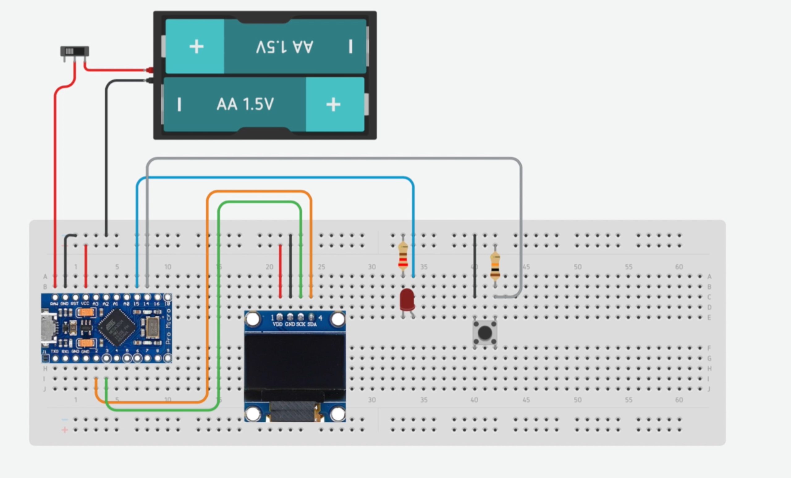
Now that we’ve got the game running on our first Arduino, let’s try and get the second one playing the Chrome Dino Game on the first.
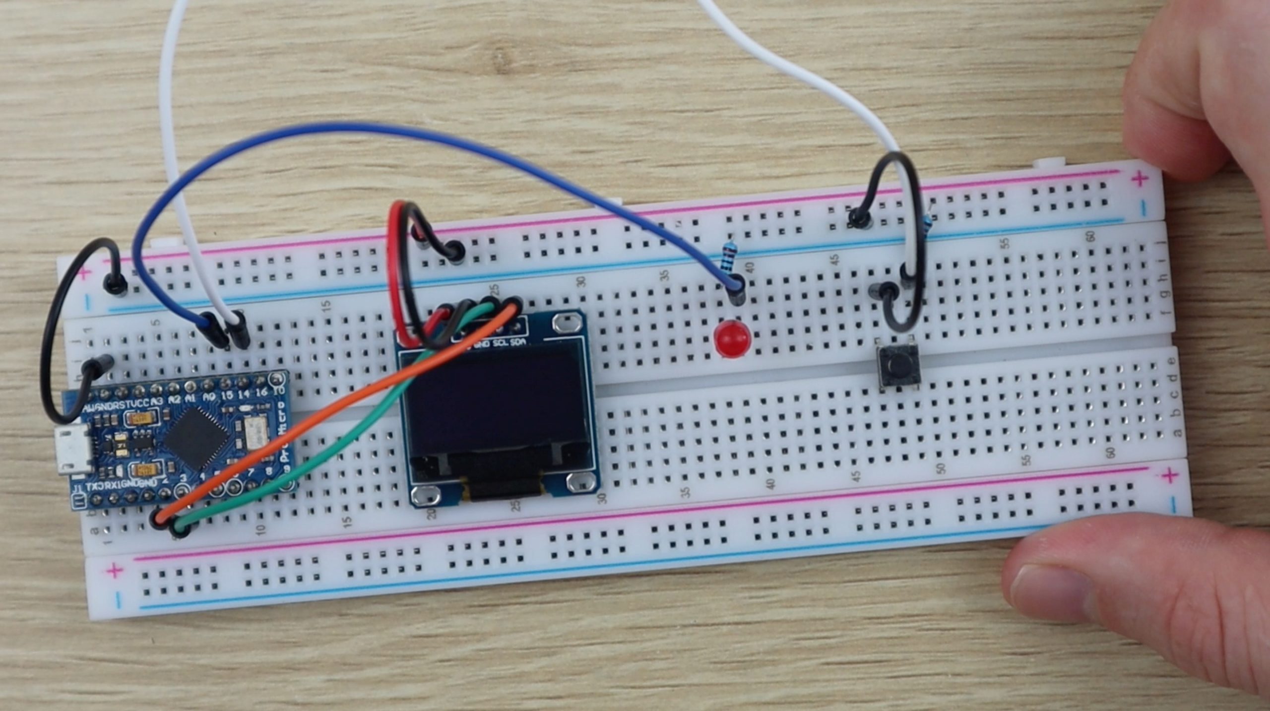
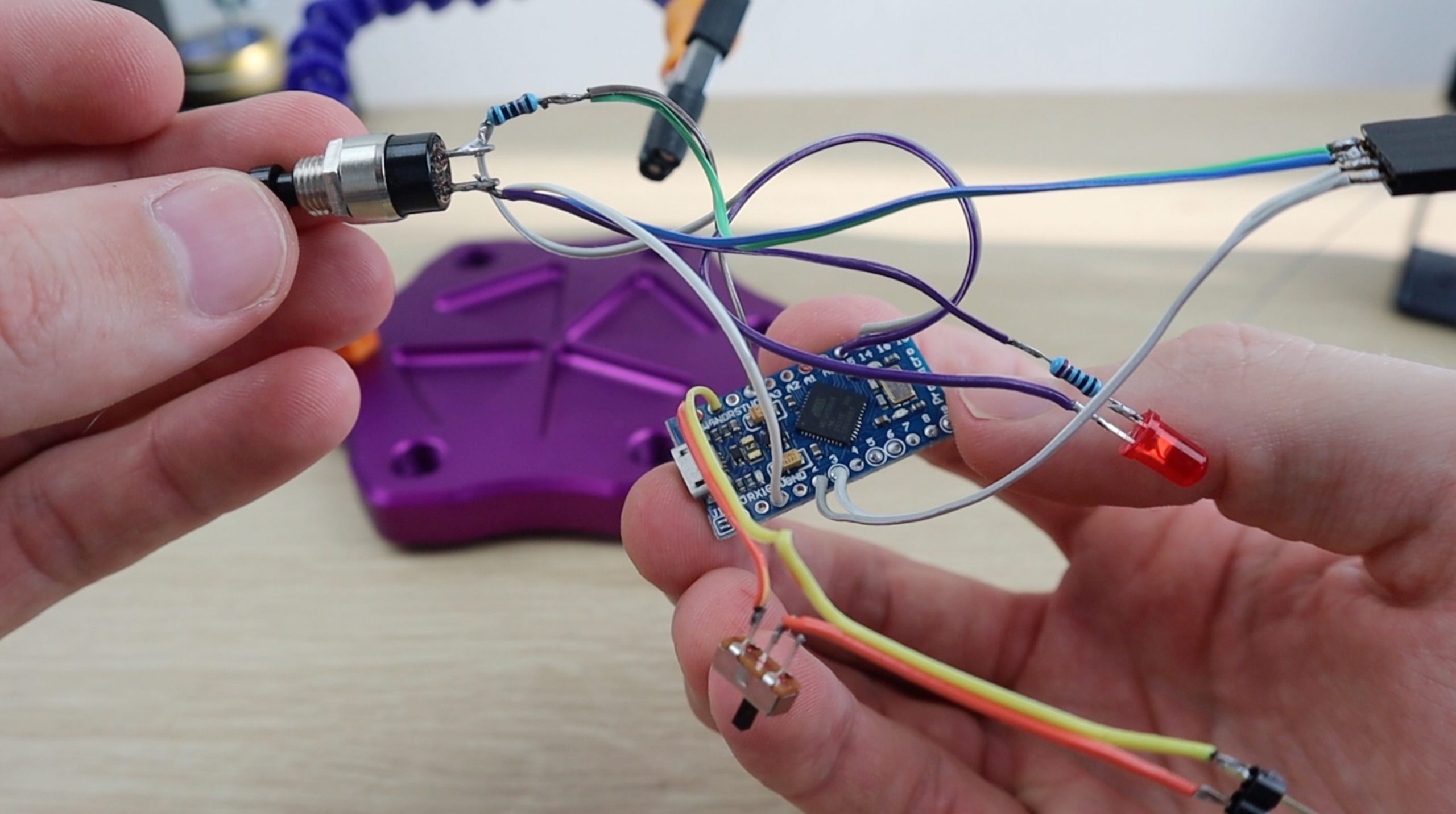
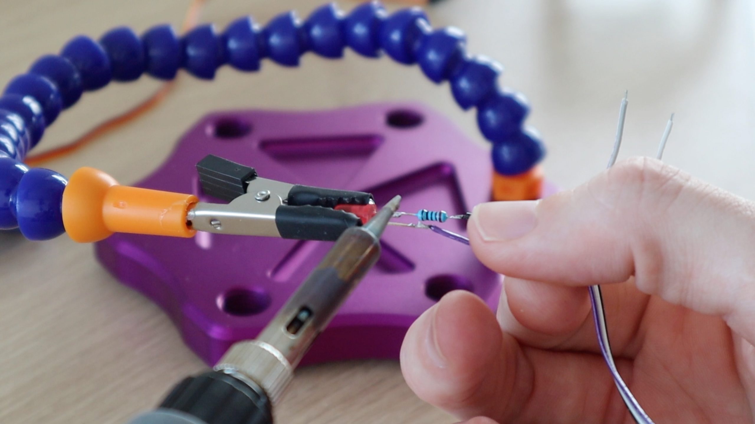
The components and wiring are quite simple, they involve basic starter circuits for the LDR, LED and servo. I initially included the LED to light up when each cactus was detected but the light started interfering with the LDR, so I turned it off. You can leave this LED out if you want to or cover it up slightly with tape so that it doesn’t interfere with the surrounding components.
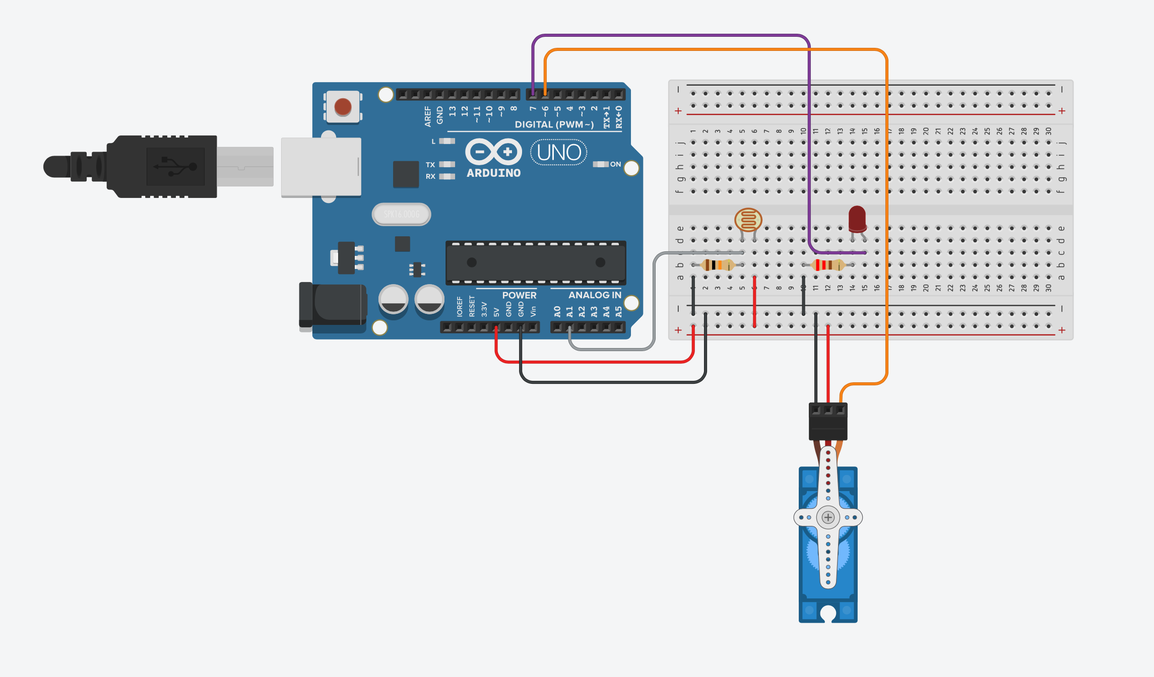
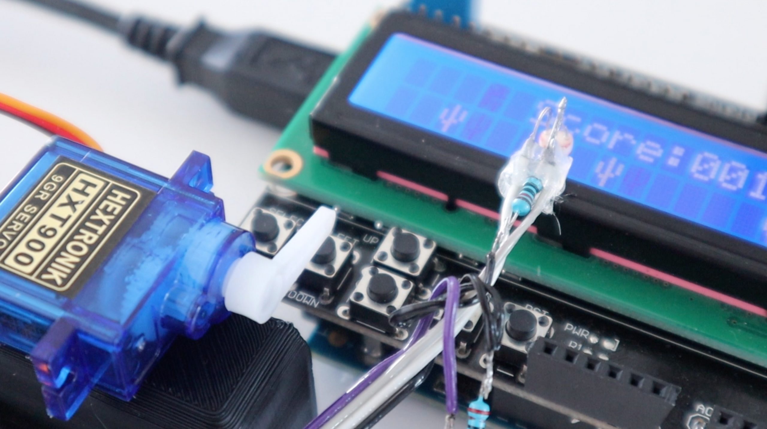
I connected the components together using a few strips of ribbon cable and some header pins to make it easier to plug into the Arduino and the servo.
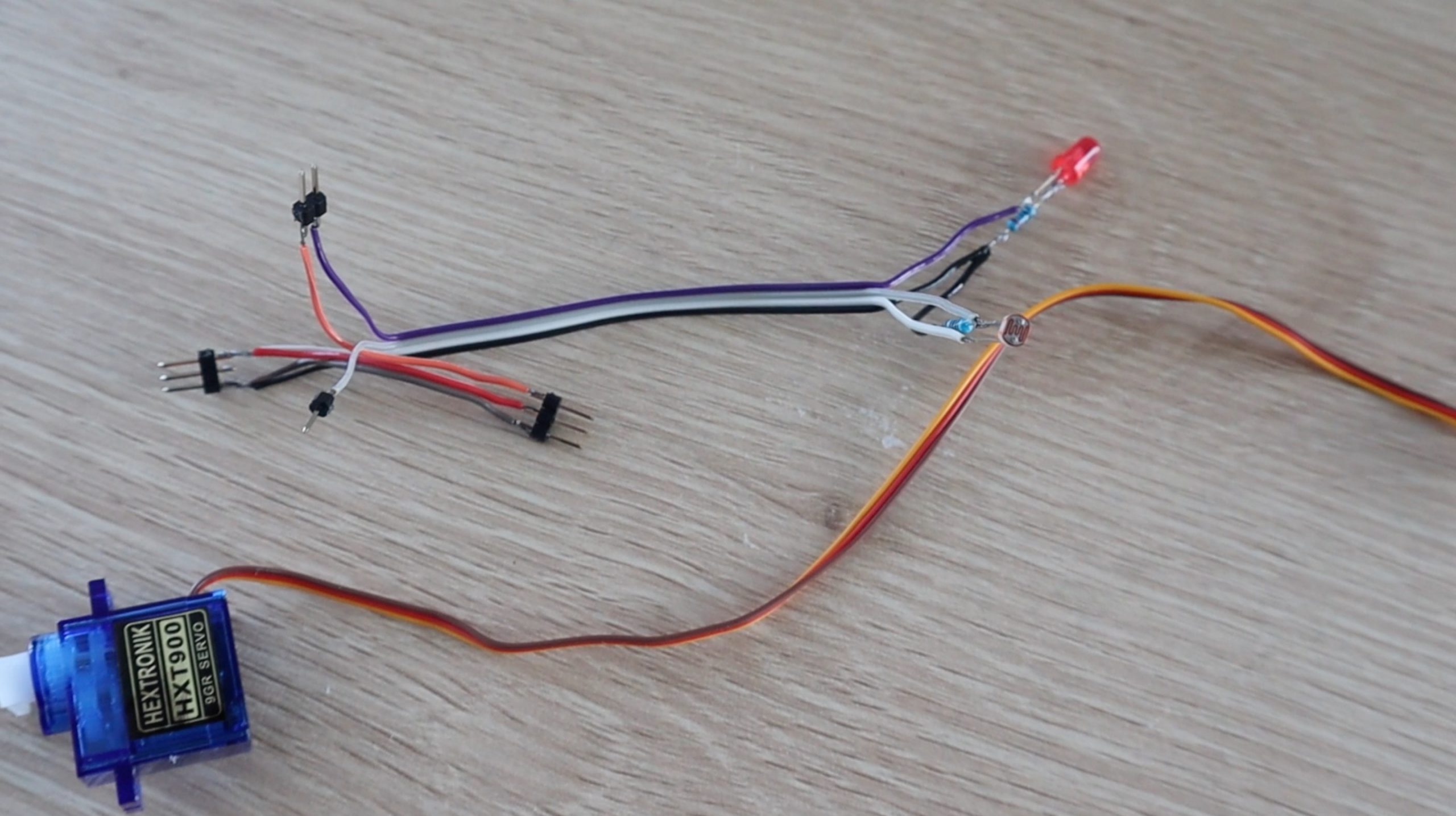
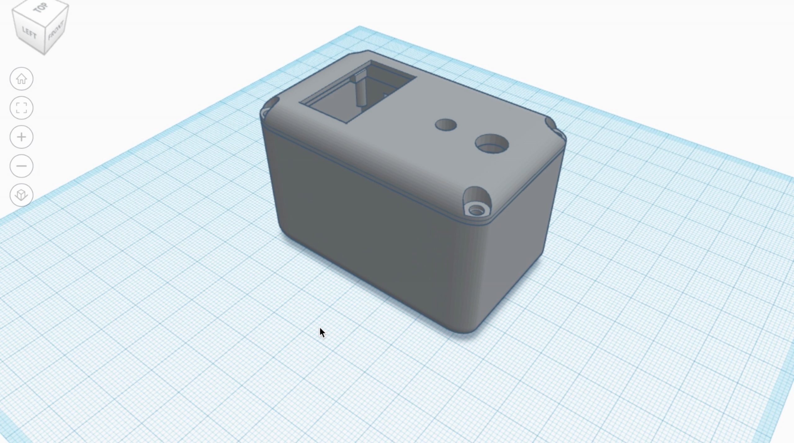
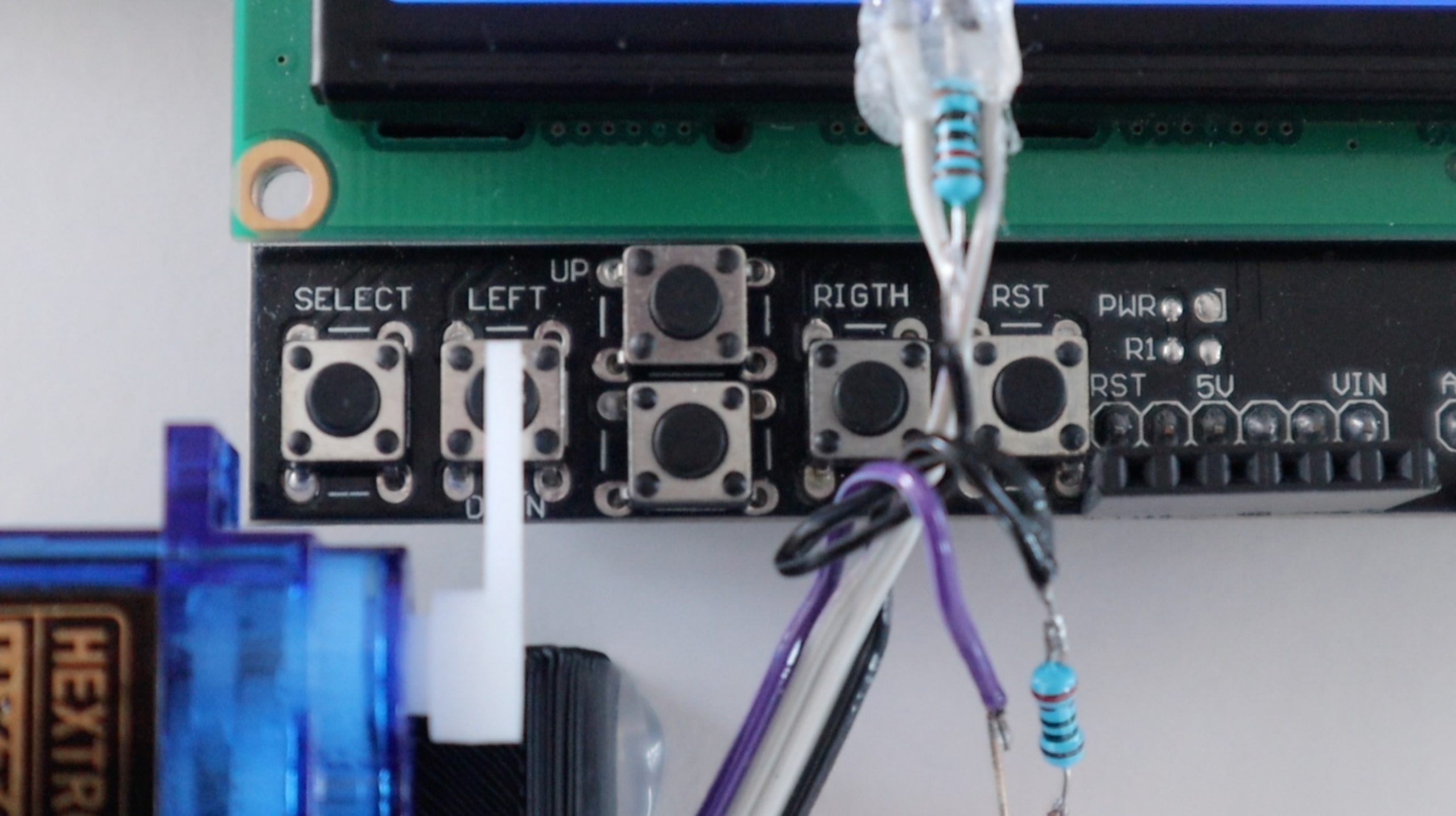
You’ll need to glue the servo onto a box or stand just above the left button on the keypad shield so that the servo arm pushes the button down when it rotates. You’ll then need to glue the LDR onto the edge of the LCD screen as close to the screen as possible. It needs to be positioned over the 7th character from the left of the display in the second row.
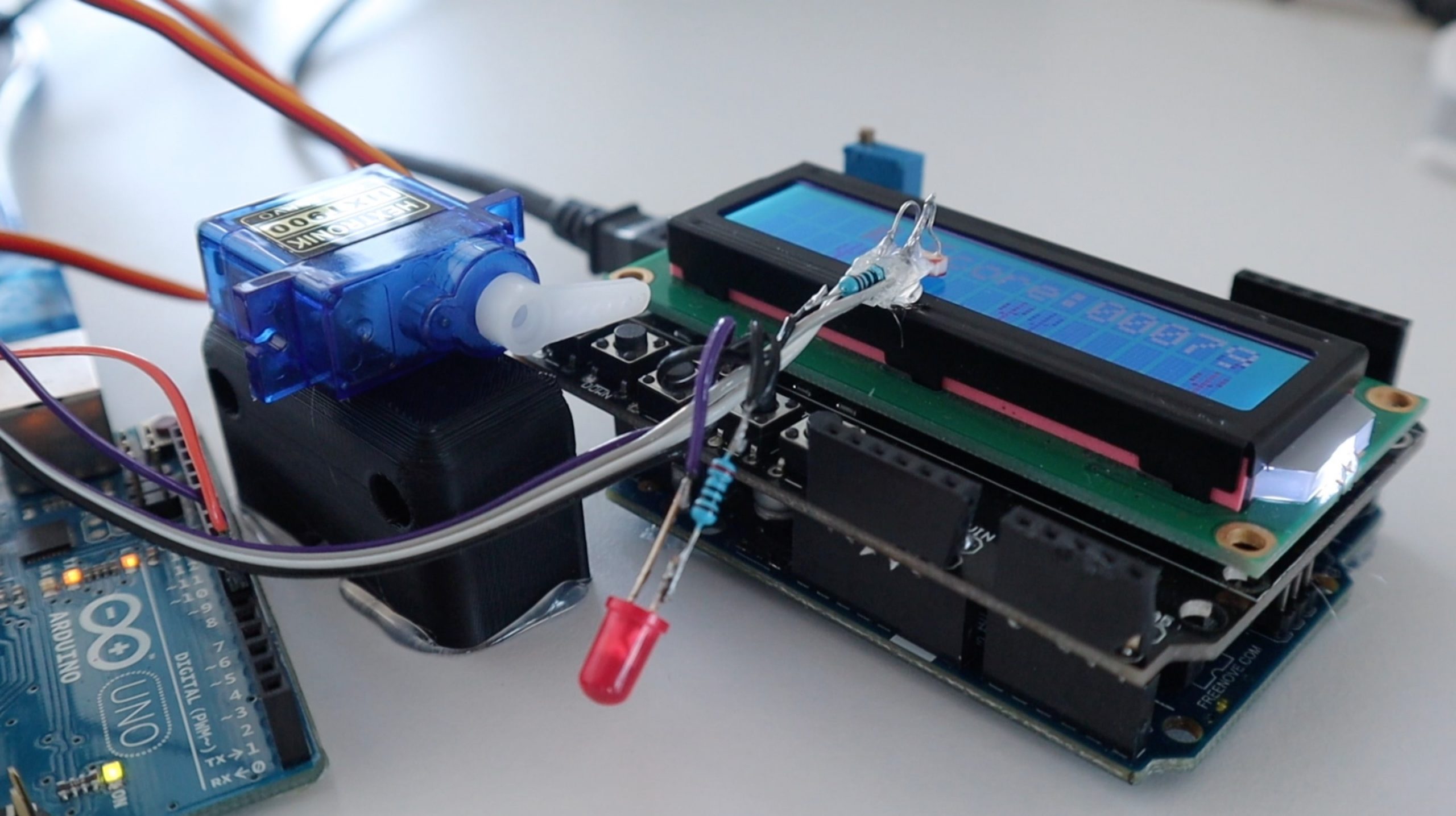
Make sure that the LED is covered, turned off or pointed away from the display so that the light from the LED doesn’t interfere with the LDR sensing the cactuses. The first few runs I had were interrupted by the LED causing false cactus readings by the LDR, so it turned it off.
Now let’s have a look at the player code.
//Michael Klements
//The DIY Life
//8 May 2020

#include <Servo.h>

Servo player;         //Create a servo object to control the button servo
int cactus = 0;       //Variable to read in LDR value
int cactusVal = 770;  //LDR Sensor value when detecting a cactus

void setup()
{
  //Serial.begin(9600);
  player.attach(6);     //Set the player servo pin to pin 6
  player.write(75);     //Set the servo to an initial position just above the button
}

void loop()
{
  cactus = analogRead(A0);          //Read the output from the LDR to detect a cactus
  //Serial.println(cactus);         //Used for calibration
  if (cactus > cactusVal)           //If a cactus is detected
  {
    player.write(60);               //Move the servo to push the jump button
    delay(300);                     //Wait 300 milliseconds
    player.write(75);               //Move the servo back to the initial position
    delay(100);
  }
}
Download The Code – DinoGamePlayer
We start by including the servo library to control the servo.
We then create a servo object called player to control the servo and then create two variables, one to store the value read from the LDR and a second to store the light level set point when a cactus passes in front of the LDR.
In the setup function we set the servo pin number and set the servo position slightly above the jump button. You’ll also need the Serial monitor for calibration, this is detailed further on.
In the loop function, we read in the LDR sensor level, then compare it to the cactus set point. If the measured level is greater than the cactus set point, indicating a cactus is passing the sensor, then we move the servo downwards to push the button, wait 300 milliseconds for the servo to move and for the game to register the input and then move the servo back up for the next push. The second delay is to avoid repeated servo movements, this could be reduced to 50ms.
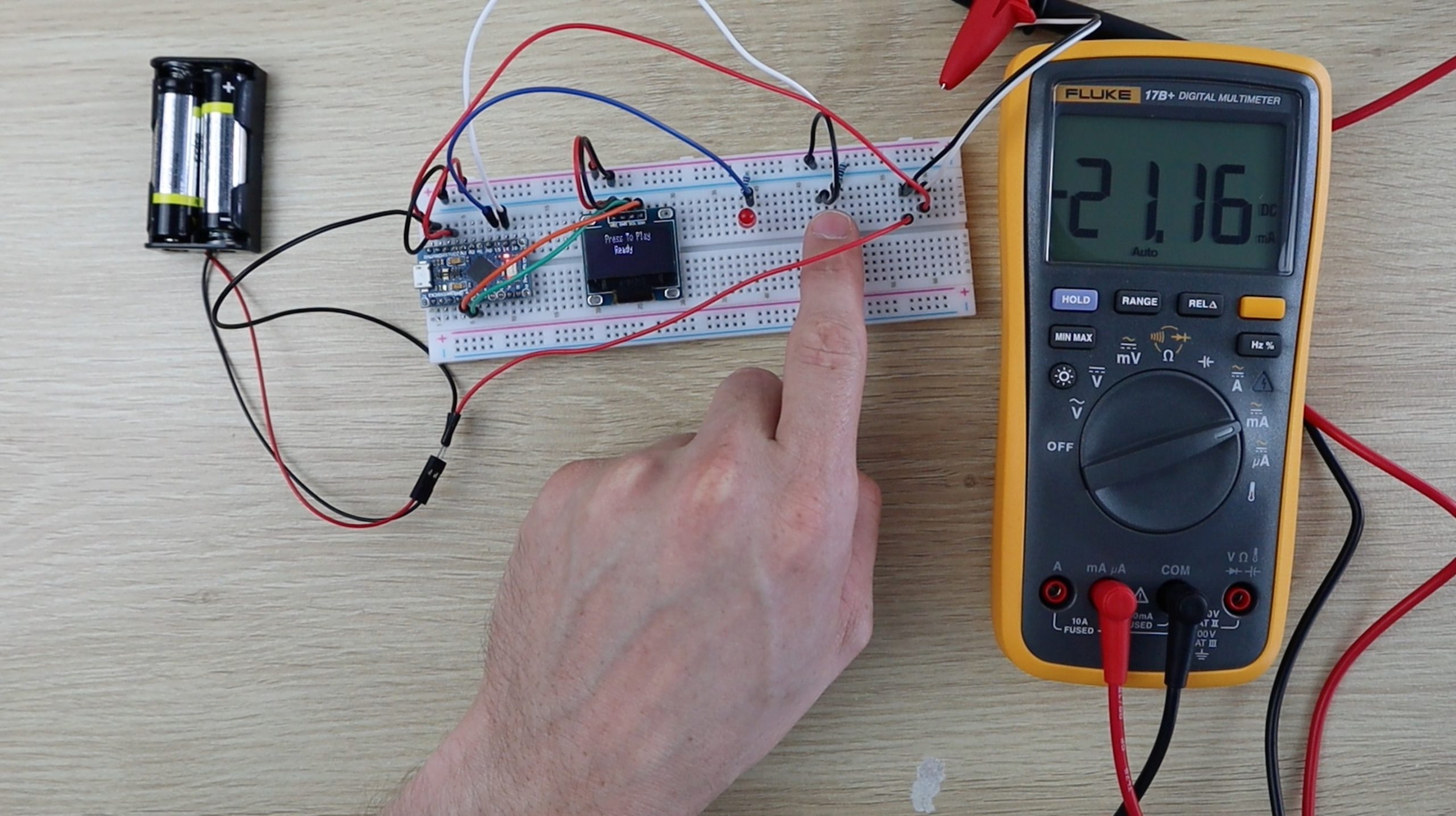
I’ve also included a serial monitor printout of the sensor value which is used initially to set the cactus value set point. You’ll need to run the game and display the sensor values and then see what value is measured when a cactus runs past the sensor and update this value in the code accordingly. This step is detailed in the video at the beginning of the project.
One Arduino Playing The Chrome Dino Game On Another
Upload the code and calibrate the sensor and you’re ready to try it out. Startup the player Arduino first and then start the game on the other. Press the reset button on the LCD shield to start a new game.
It initially looks like the sensor is making the dinosaur jump a little too early, but it doesn’t hit the cactuses and you need to it respond quickly later on in the game. It starts to look better as the game progresses.
You may need to make a few adjustments to the servo travel limits and to the cactus detection set points in your code to get it to work correctly.
Also, position the LDR as close to the LCD as possible. These LDRs are really sensitive, I noticed a significant fluctuation in the measured values with me moving around the room or at different times of the day, so It would be a good addition to add a pot to adjust the set point at any time. This way you could get it to work in any light conditions and use it on the Arduino game or your computer without having to change the code.
Let me know in the comments if you’ve tried playing the Chrome Dino Game on an Arduino or tried getting an Arduino to play the Chrome Dino Game.
Share This Guide