Everyone loves a neat and clean home. However, a long list of daily obligations doesn’t leave you with enough time to tidy up, which can lead to stress. Here are some liberating cleaning methods to work their magic for multitasking persons and busy parents.
Use alcohol for chair stains
Many chairs are now made with microfiber upholstery, which makes them harder to clean. Rub the stain with alcohol and wipe with a clean sponge. Alcohol won’t leave a mark because it evaporates faster than water. You don’t have to worry about alcohol fading your fabric either. Make a mixture of one part dishwashing liquid and two parts hydrogen peroxide, spray it on the stain, rub it in, let stand and wash.
Baking soda is good for trash odors
Sprinkle baking soda at the bottom of a trashcan to keep the unpleasant odors away. This is particularly helpful if you have cans in a hot garage or porch. If you’re using trash bags, roll up an old newspaper and put it in the bottom of the bag. The papers will absorb the odor and prevent unwanted leakage from the discarded products in the bag.
Keep sinks and stove clean
Dirty sinks, stovetops, or counters are signs of a messy home. Make a habit of wiping down the surface you’ve just used. It takes only a few seconds to wipe down the used area, and it will stay clean and disinfected, ready for the next use. Additionally, if you don’t clean the surfaces regularly, grease and grime will build up over time and make it harder to restore their original shine, but any quality polish will keep those kinds of surfaces neat and clean.
Don’t neglect glass surfaces
Sometimes, it’s easy to neglect your windows, mirrors, or any other glass surface, especially if you don’t have kids and pets to make it dirty with their little fingers or paws. You can use traditional window cleaning products, but if you notice that there’s no change, then you can opt for a water-based hydrophobic glass coating that can repel dirt by using water that picks up the dirt and make it easier for you to remove it. That way your windows and glassy decor will stay cleaner for much longer, which will make your home look and feel more pleasant. Also, such coating products can also be used in your car and other glass surfaces in your home.
Cleaning your blinds with a pair of socks
Dust can accumulate on your blinds. This may not have occurred to you, but a pair of old socks can help you clean your blinds. Mix equal amounts of water and vinegar in a bowl, put a sock over one hand, dip it into the mixture and go over the blinds. Use the other sock to wipe away the dampness.
Lemon helps in cleaning microwaves
If your children made a mess in the microwave while trying to reheat leftovers from dinner, a lemon can save the day. Slice the lemon into a bowl of water and put it in the microwave on high for 3 minutes. Keep it in the microwave for 3 more minutes and then just wipe out the inside of it. No tough cleaning required. If you want to get rid of odor quickly, place a bowl of white vinegar inside the microwave, shut the door, and keep it there for an hour.
A bathroom with essential oils
Keeping your bathroom fresh can be a real challenge, particularly during the summer months, when your house is cramped with guests and your children’s friends. A great trick you can use is to add a few drops of your favorite essential oil to the inner roll core of your toilet paper. Every time the roll is used, a pleasant smell will be released.
Get rid of old clothes
If you’re wondering which pieces of clothes to retain, simply apply the old rule: If you haven’t worn it in a year, dump it. Avoid cluttering your closet with old stuff you hardly ever wear. Instead, treat yourself with something new. If an old item goes out, a new one can take its place, but be careful not to get overwhelmed with new pieces without dismissing the old ones.
Keep your garage neat
Check the state of your garage every six months and get rid of anything you don’t need. You can have plenty of things, like old bookshelves and rugs, that only take up space in your garage. It’s a good idea to have labeled bins for different stuff. This will make finding things much easier.
Balancing work and home is challenging and we need all the help we can get. Use these tips to make your home fresh again, stress-free.
Last week, I put together a water-cooled Raspberry Pi 4 and overclocked it to 2.0Ghz to see how well the cooling system would work. It was really effective and only saw a couple of degrees increase in temperature when running at full CPU load for 5 minutes, even when overclocked.
This sounds good, but the PC water cooling system used on the Pi costs a couple of times more than the Pi does, and uses more power than the Pi to run too. So I wanted to have a look at whether some other options could be more cost-effective, and how well they work to keep the Pi cool in comparison.
I got together a couple of common Raspberry Pi cooling options, and I’m going to be comparing the running temperature and cost for each of them. We’ll be looking at just putting aluminium heat sinks onto the Pi, then using the heat sinks in conjunction with a fan in a compact case, then a more significant fan and heatsink combination called an Ice Tower, and finally the water cooling system.
Here’s a video of the tests and results, read on for the written guide:
Purchase Links For The Raspberry Pi Cooling Solutions
Note: Some of the above parts are affiliate links. By purchasing products through the above links, you’ll be supporting this site, with no additional cost to you.
Testing The Raspberry Pi Cooling Options
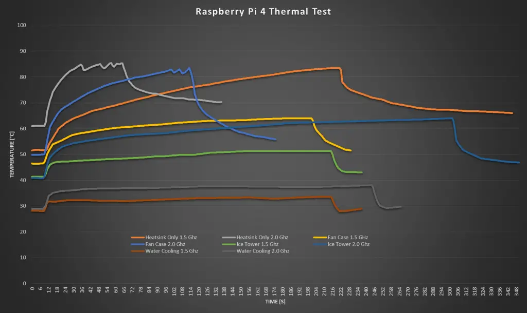
For each cooling option, I’ll start by running the CPU at full load at the default clock frequency of 1.5Ghz, and then we’ll do a second test with the Pi overclocked to 2.0Ghz. I’ll record the CPU temperature at 1-second intervals and plot these onto a graph for each.
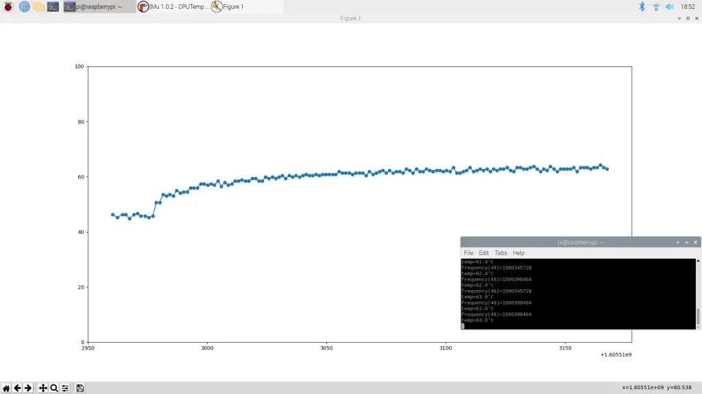
I’ll collect the data like this:
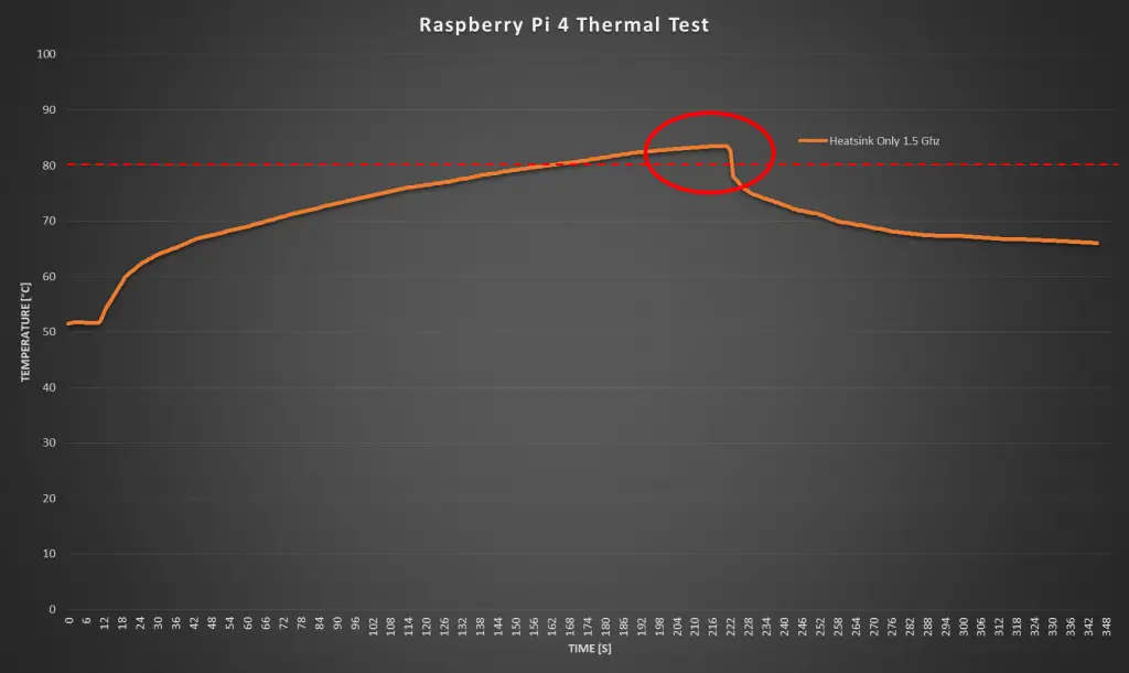
The Raspberry Pi 4 allows the CPU temperature to go up to 80°C before it starts throttling the CPU performance to lower the temperature and prevent the CPU from burning out.
From the test results, it looks like mine starts throttling the CPU around 83 or 84 degrees, but we’ll work on 80 as the documented limit.
So if any of the cooling options exceed 80 degrees then you’re going to start getting limited performance from the Pi, and you’ll probably reduce its life by running it this hot for extended periods of time.
It’s also worth remembering that this test just runs the CPU at maximum load indefinitely. This represents a worst case scenario. In practice, your Pi will likely only use a fraction of the CPU capacity for most of its running time, obviously depending on your application and usage.
Testing The Aluminium Heat Sinks
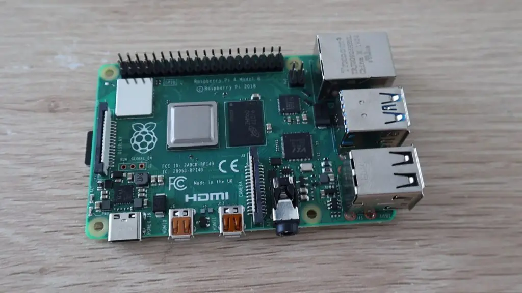
Let’s start out with the plain aluminium heat sinks.
This is by far the cheapest option, you can usually get a set of these for around $1 – $2. They have a peel-off back and you just stick them onto the heat-generating components on the Pi.
The benefit of the heat sink only option is that it is completely silent, so if you’ve got a low-intensity application for your Pi then this might be a good option.
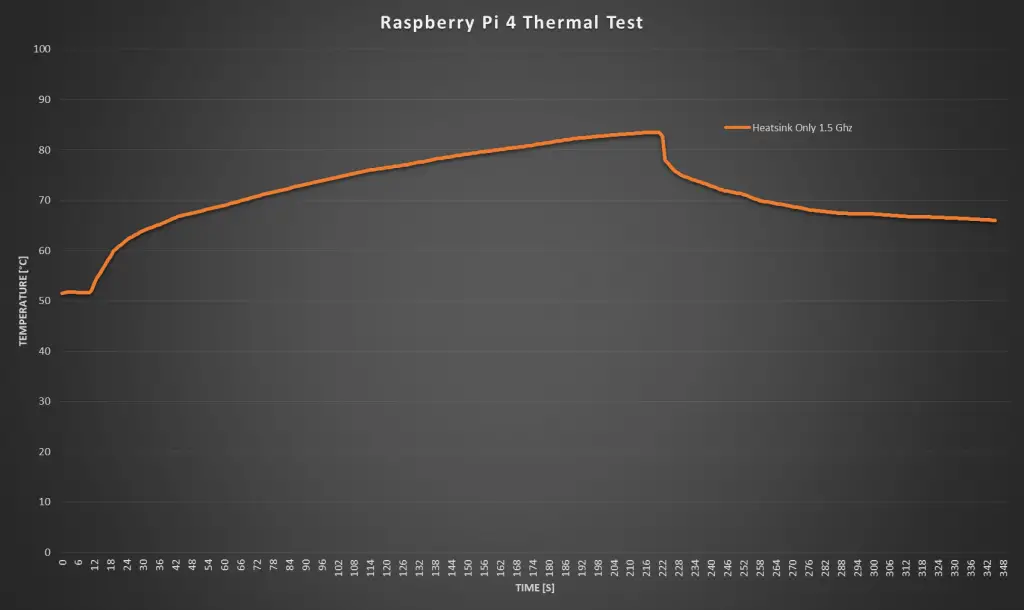
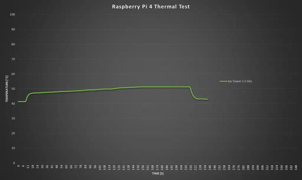
Let’s see how well they do in the thermal tests. We’ll start off at 1.5 Ghz.
Right off the mark, before even starting the test, the Pi is already running quite warm. We’ve got a starting temperature of around 51 degrees.
It took around a minute and forty seconds before the CPU was at 80 degrees and the performance started getting throttled.
There isn’t much point in continuing the test once we’ve hit 80 degrees as we’re then losing CPU performance and the temperature will just stay around 80 degrees as the Pi manages the CPU load.
So, I stopped the test and you can see that the temperature initially dropped off quite quickly, but flattened out after another minute or so to around 65 degrees. So it would take a long time to get back down to the 50 degree starting temperature.
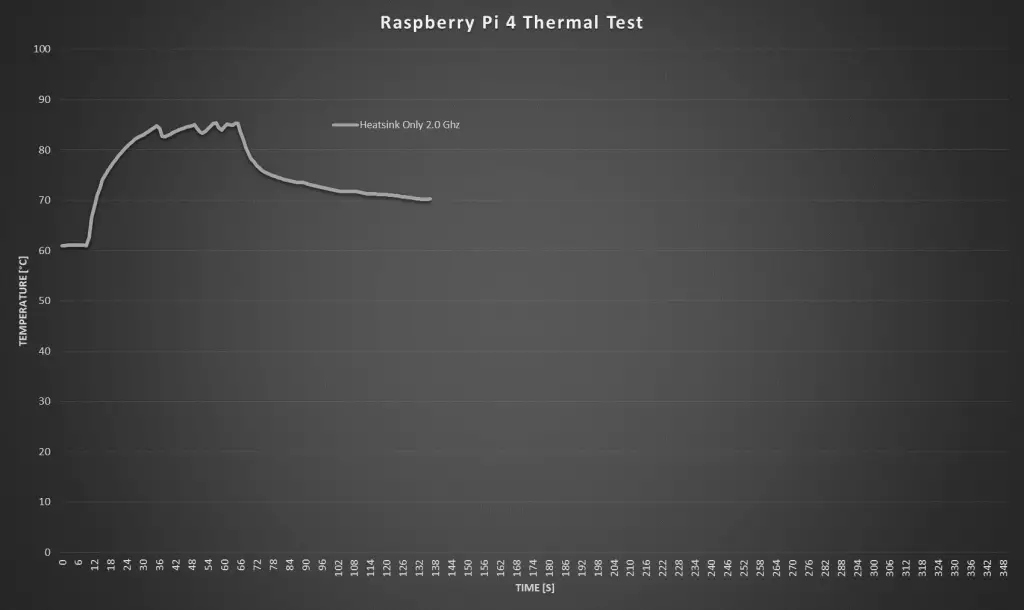
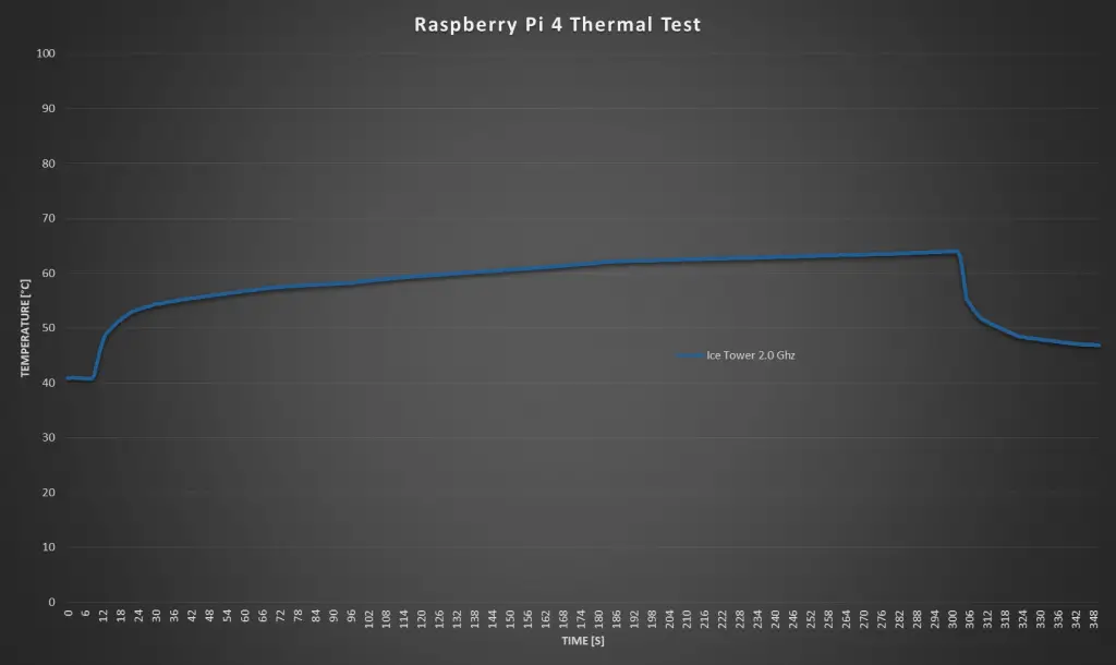
Next I increased the clock frequency to 2.0Ghz.
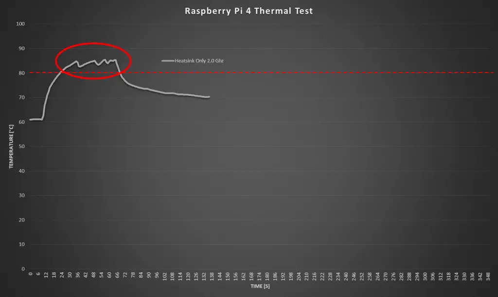
Running at 2.0 Ghz, we had a starting temperature of around 61 degrees at idle, which is already pretty high. It only took about 10 seconds to reach 80 degrees once the test was started.
You can also clearly see the Pi throttling the CPU performance on this graph.
The cool down curve after the test is quite similar to the 1.5 Ghz test, flattening out at a slightly higher temperature than at the start of the test.
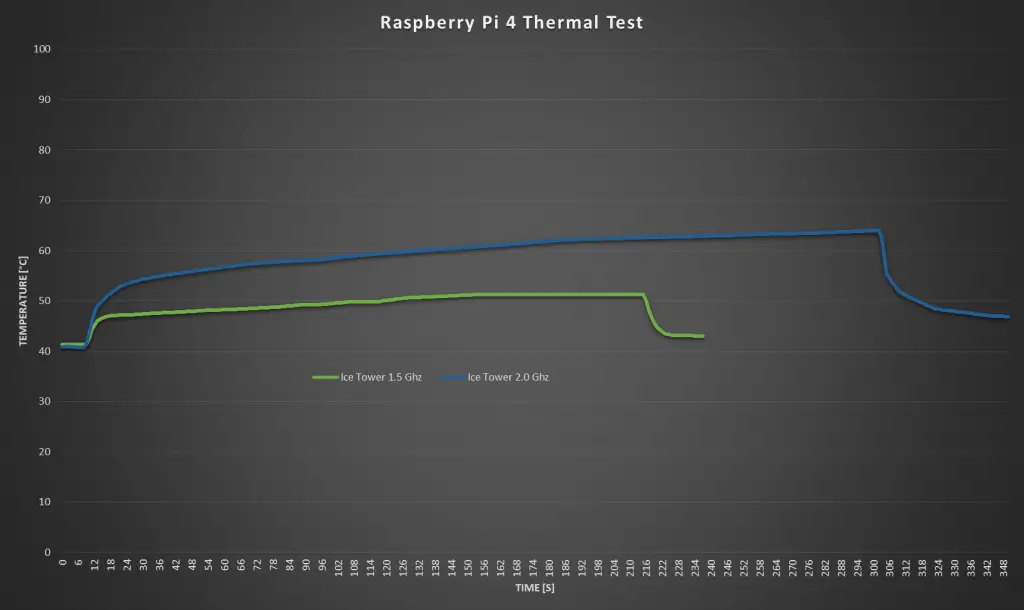
Here are the two heat sink only graphs plotted together. You can see how much faster the 2.0Ghz test increased the CPU temperature, it’s basically unusable without any active cooling.
Testing The Fan Case
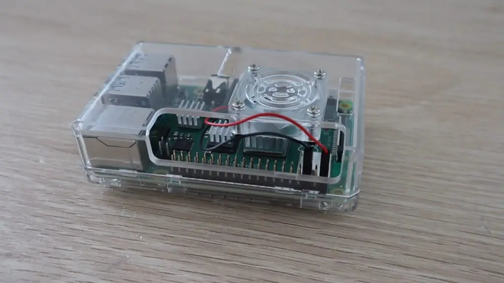
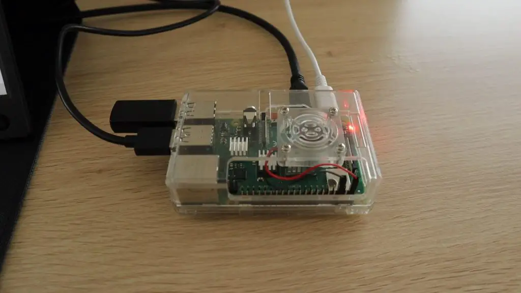
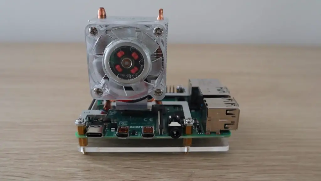
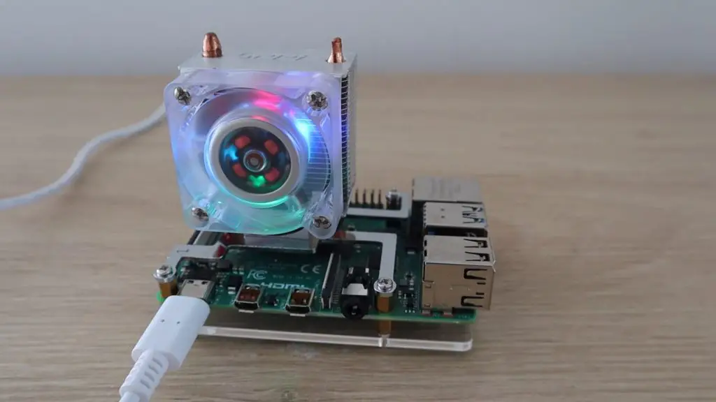
Next let’s move on to the fan case.
I typically enjoy making my own cases for Raspberry Pi’s, but I had this one from an earlier version Pi lying around, so I just opened up the cutouts for the HDMI ports on the side to make it fit.
The fan and CPU are in the same place, so the fan is blowing down directly onto the CPU heat sink. These acrylic cases with fans as also quite a cheap option and usually range between $5 and $10 for a case, including the fan and heat sinks.
These small fans are quite noisy, so it can be distracting if you’re just using your Pi as a desktop computer or you use it as a media player on your TV. Have a listen to the sound it makes in the video at the beginning of this post.
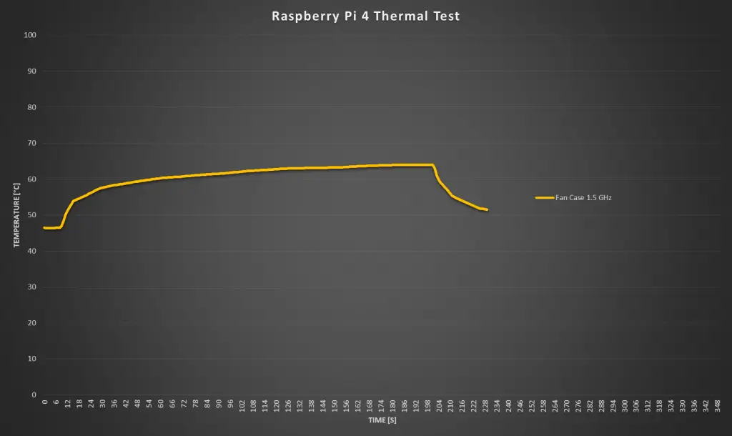
Let’s see how effective the fan is at keeping the CPU cool.
The fan has already helped reduce the starting temperature to a lower, 46 degrees. I was then able to run the test for a full three and a half minutes without the Pi overheating. The temperature seems to stabilise around 65 degrees. The temperature also drops off much faster now once the test is stopped.
So you can comfortably use your Pi at any CPU load in a fan case at 1.5 Ghz.
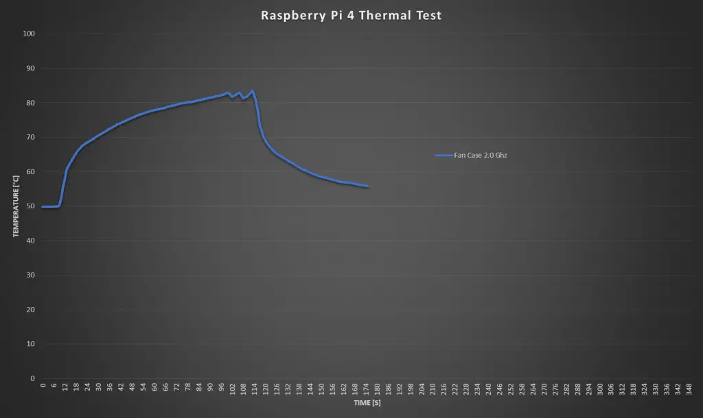
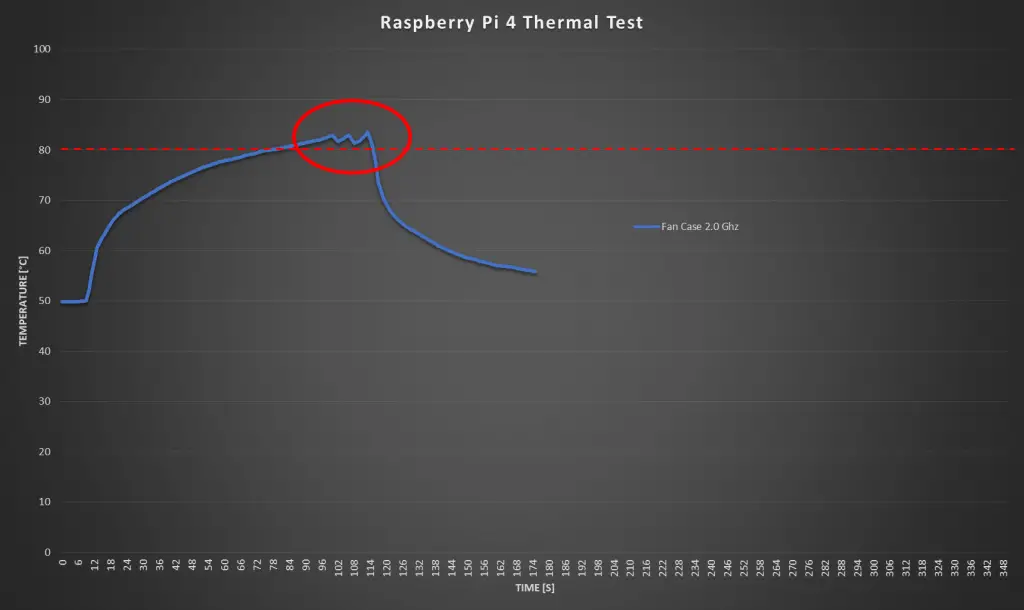
Now let’s try overclocking it to 2.0 Ghz and see if the temperature still stays under 80 degrees.
The idle temperature at 2.0 Ghz increase a little, to 50 degrees and unfortunately we weren’t able to complete the test at 2.0 Ghz.
The Pi overheated a little over a minute into the test and started throttling the CPU performance. There was still a sharp drop in temperature once the test stopped, so the case fan helps quite a bit, but is not an effective option if you’re going to be overclocking your Pi.
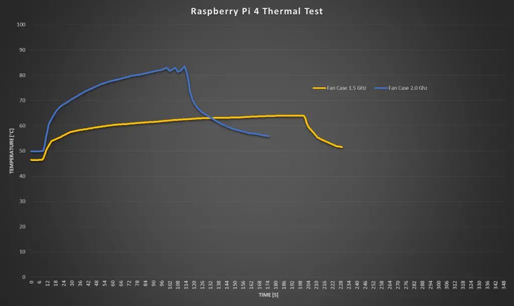
Here is a comparison between the two tests with the fan case.
Testing The Ice Tower
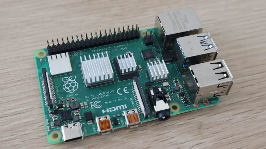
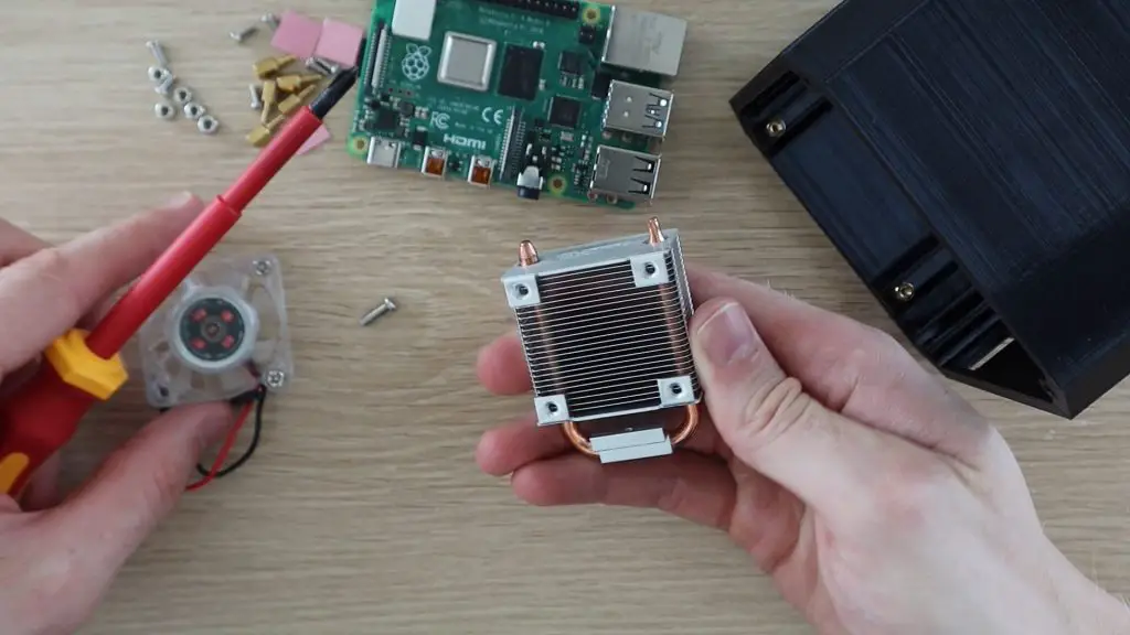
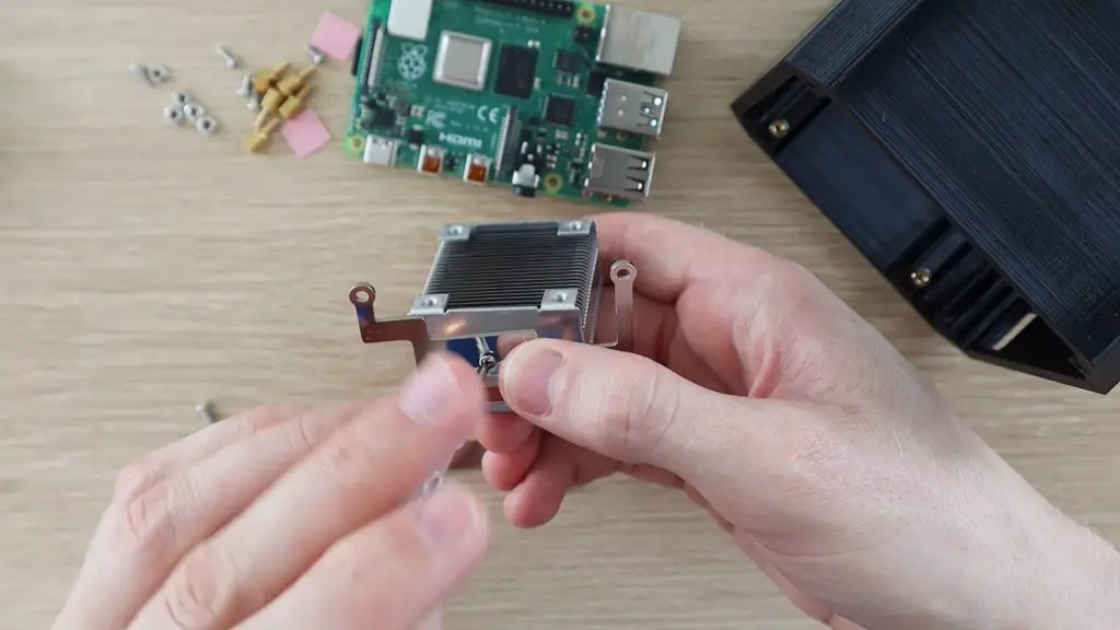
Now lets have a look at the Ice Tower.
This has become a popular option for Raspberry Pi cooling, and they make a low profile version now too. They also quite affordable, costing around $20 to $25. The Ice Tower has a much bigger heatsink with heat pipes to a large radiator with a significantly larger fan than the case.
The Ice Tower is also quite loud, its about the same sound level as the case fan, so let’s see if it does better in the thermal test.
Our starting temperature is now lower than with the case, at just 41 degrees and I was able to run the test for the full three minutes and it only went slightly over 50 degrees. This is more than a 10 degree difference over the fan case. You can also see that the temperature returns to almost the same as the idle temperature just 20 seconds after the test is stopped, which is the quickest so far.
The Ice Tower is looking promising for overclocking, so lets try taking it up to 2.0 ghz.
There wasn’t much difference between the idea temperature at 1.5 Ghz and at 2.0 Ghz, at 2.0 Ghz we again started around 41 degrees.
The Ice Tower managed the full run of 3 minutes without going much over 60 degrees, but it looked like it was still steadily increasing. So I left it running for a further 2 minutes to see how it went and it started flattening out at about 65 degrees.
So an Ice Tower is a great option for Raspberry Pi cooling, even when overclocked. It is quite a lot more than the previous two options and you’ll still need to get a case or cover for your Pi, but there are a few options available with a cutout specifically for the Ice Tower.
Testing The Water Cooled Pi
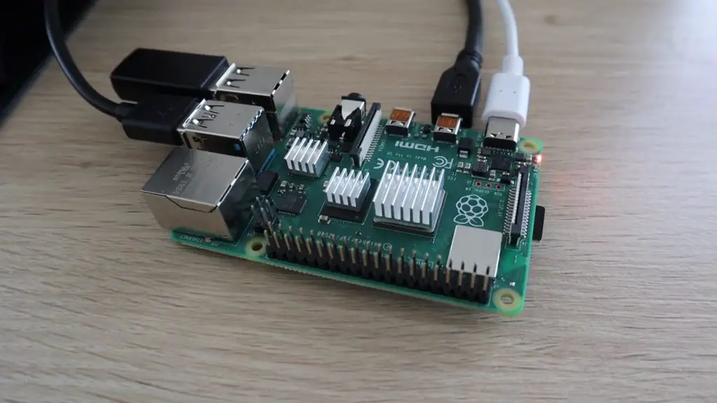
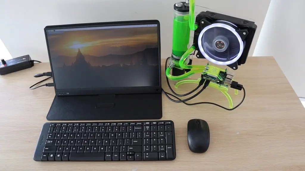
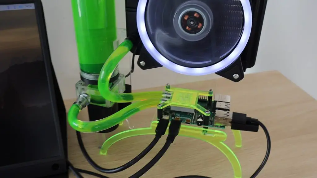
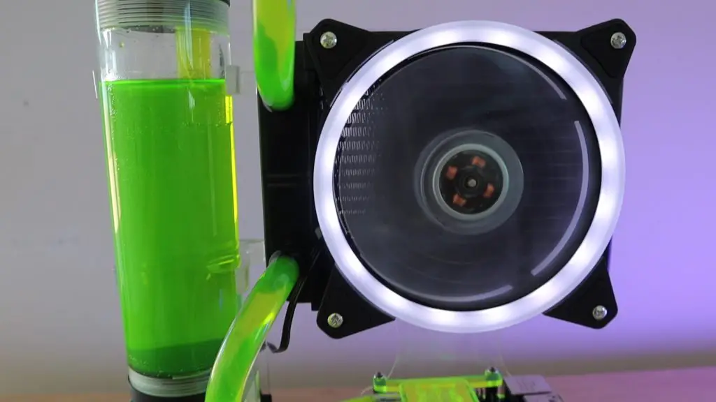
Now let’s look at the final option, the water cooling system which I built for mine.
This setup is by far the largest and the most expensive. The cooling system cost around $100 for all of the parts to assemble it and this was using a cheap non-name brand kit, which is definitely not the best quality.
One benefit of this setup is that it is much quieter than the fan case or the Ice Tower, as the larger 120mm fan turns much slower.
Let’s see how the water cooled setup does in the thermal test.
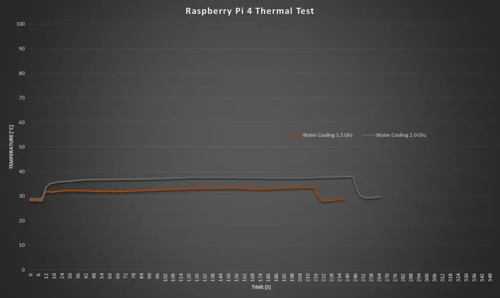
Starting with the 1.5 Ghz test, the idle temperature is now just 28 degrees, which is over 10 degrees lower than the Ice Tower and 20 degrees lower than the heat sink option.
There was a noticeable spike in temperature when the test started, but it remains fairly constant at around 32 degrees for the three and a half minutes of the test. It also dropped back down to the starting temperature almost instantly when the test was stopped.
Now let’s try overclocking it to 2.0 Ghz.
At 2.0 Ghz, we have the same starting temperature of around 28 degrees. We again have a noticeable spike when starting the test, but the temperature stays around 38 degrees for the rest of the test. I ran this test for four minutes before stopping it, and the temperature dropped off almost instantly again when it stopped.
So the water cooling system definitely works the best at keeping the Pi cool and providing a much quieter cooling solution. But it is way more expensive than the other options and is much more difficult to assemble. It’s also not exactly compact, this system is a couple of times larger than the Ice Tower and that’s already considered to be a large heatsink for a Pi.
Summary Of The Raspberry Pi Cooling Tests
Here’s an overlay of all of the Raspberry Pi cooling options which I’ve tested today:
It’s quite noticeable just how much better the ice tower and the water cooling circuits are for high CPU loads, especially when overclocked. Heat sinks only and fan cases are great if you’re going to be using your Pi for light loads, such as a Pi-hole, network storage, or WiFi camera. If you’re going to be doing any CPU intensive tasks, like video editing, light gaming, or simulations then you’ll need to get a more substantial cooling solution, like the Ice Tower. And if you’re a fan of overkill like me, then you definitely need a water-cooled Pi.
Let me know in the comments section what your Raspberry Pi cooling solution is.
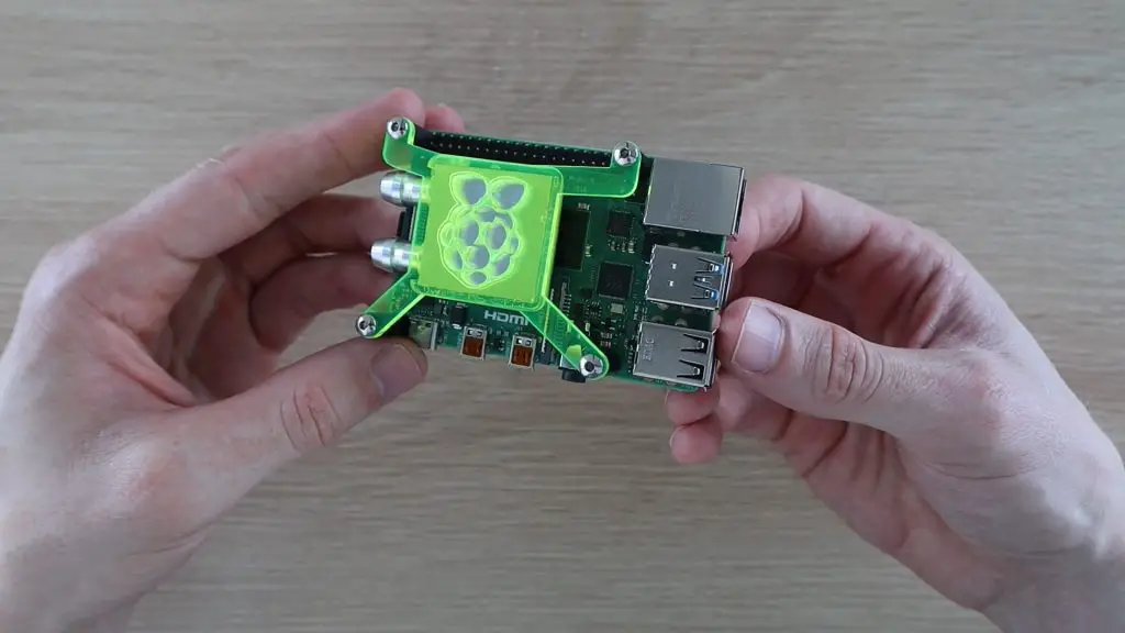
Today I’m going to see if I can use a PC water cooling kit to make a water cooled Raspberry Pi 4. I’ve seen a couple of people try this on older model Pi’s, using reducers and adapters to get to a small cooling block onto the CPU, but I’m going to try and make an adapter to fit a larger 30mm cooling block onto a Pi 4.
Just to be clear, this is totally unnecessary and is more of a let’s do it because we can, not because we should type of project. But we’ll have fun building it anyway, and hopefully it works well in the end!
Here’s a video of the build and the test, read on for the write-up:
Note: Some of the above parts are affiliate links. By purchasing products through the above links, you’ll be supporting this site, at no additional cost to you.
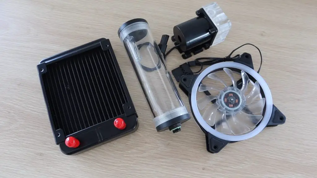
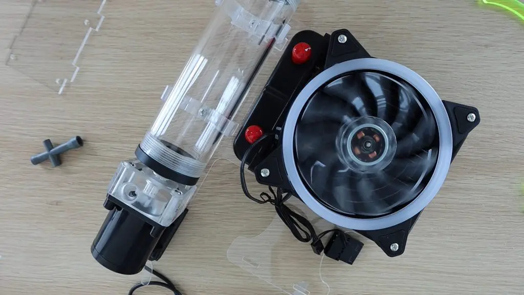
I bought a kit that included a 120mm fan and a radiator, a 12V pump, a reservoir and some tubing. These kits are commonly available online for significantly less than the name brand components sold for high-end PCs, but it’s still quite expensive just to mess around with.
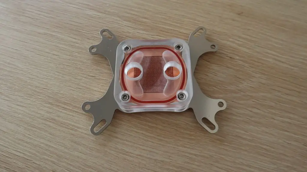
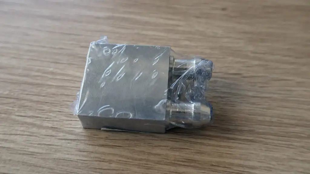
The kit also included a full size CPU cooling block. It looks quite cool (excuse the pun) but is way too big to try and fit onto the Pi, so I’m going to be using one of these smaller 30 x 30mm blocks which can accommodate a half-inch or 12mm tubing.
Building The Water Cooled Raspberry Pi 4
Mounting The Cooling Block To The Pi
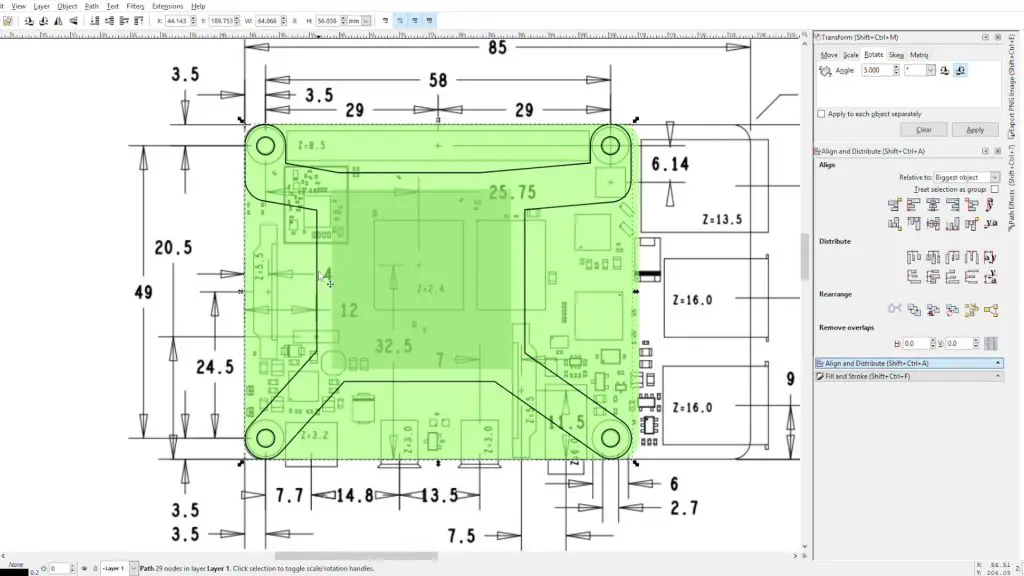
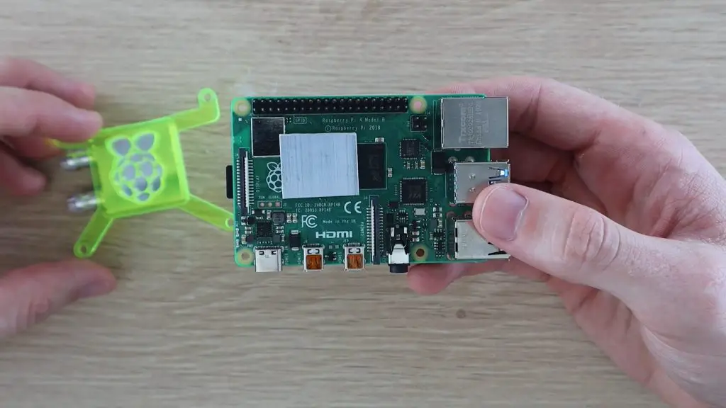
I’m going to start out by making a bracket to hold the cooling block in place on the Pi over the CPU.
We’ll need a square section to locate the block and hold it down onto the CPU and then some legs off to the four mounting holes to hold it in place. I’ve tried to avoid covering the GPIO pins and the major components, the bracket will be quite high up, so won’t interfere with any of the surface mount components.
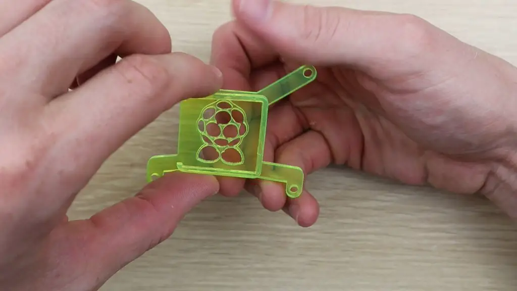
I cut the two parts for the bracket out on my laser cutter from 3mm fluorescent green acrylic.
Then glued the pieces together using some acrylic cement.
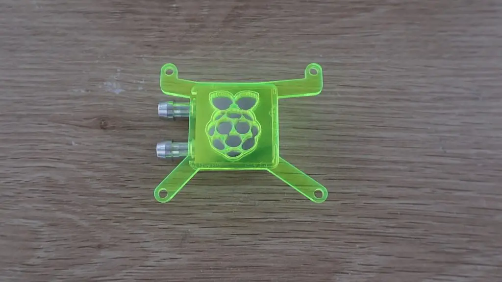
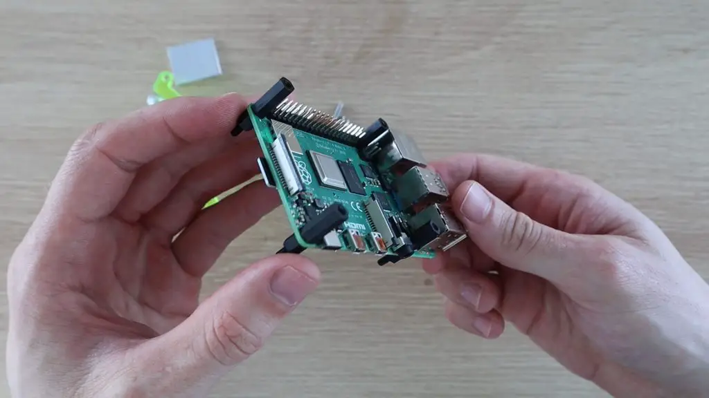
Now that we’ve got a bracket to hold the heat sink in place, lets fit it to the Pi.
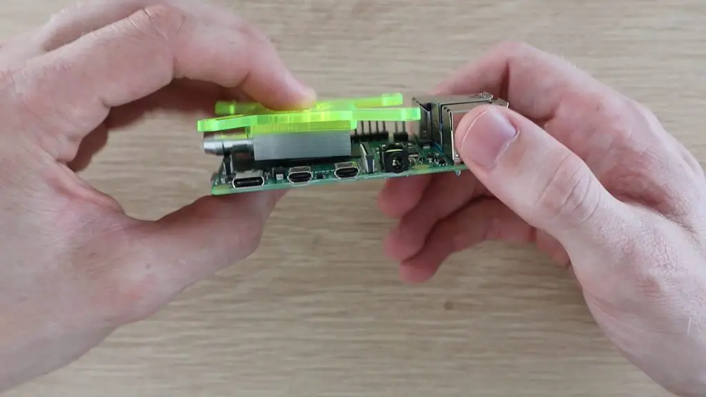
The cooling block can’t be mounted straight onto the CPU as the display connector is too high. We’ll need to put a spacer in between the CPU and cooling block to lift it above the display connector, with enough room for the tubes.
I’ve cut a section of 4mm aluminium to fit on top of the CPU to space the cooling block away so that it clears the display connector.
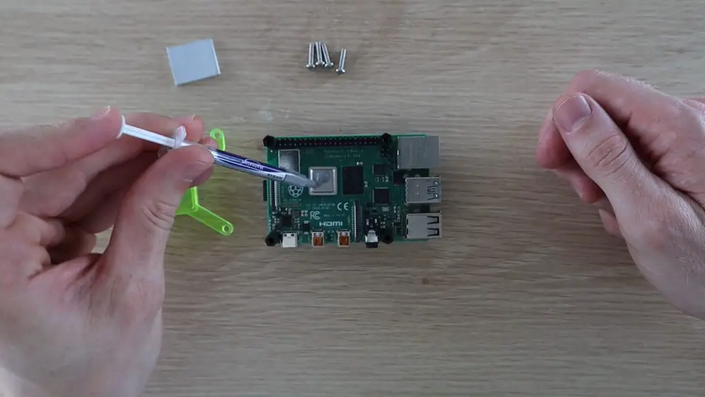
Next, I’m going to use some nylon standoff mounts for the screws which hold the cooling block bracket to screw into. I’ll hold these in place with some shorter nylon standoffs underneath the Pi.
I’ll use some thermal paste between the CPU and the spacer and then again between the spacer and the cooling block.
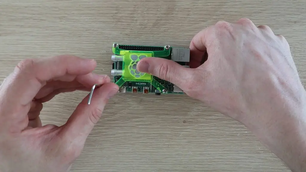
The acrylic bracket is then clamped down onto the CPU using some M3 x 12mm button head screws.
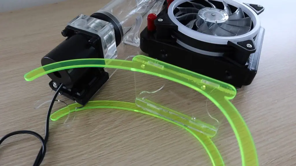
Making The Cooling Circuit Stand
Now that we’ve got our cooling block mounted onto our Pi, we can start working on mounting the rest of the cooling circuit.
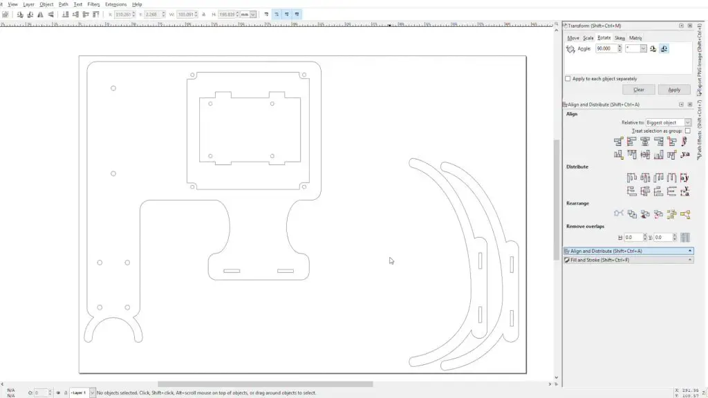
Rather than just connecting all of the components together on a desk, I decided to design a stand to mount the water cooling components and Raspberry Pi, so that it looks more complete.
I’m going to use clear acrylic for the stand with some fluorescent green legs to match the cooling block bracket. The water cooling components should just bolt straight onto this sheet once it’s been cut out.
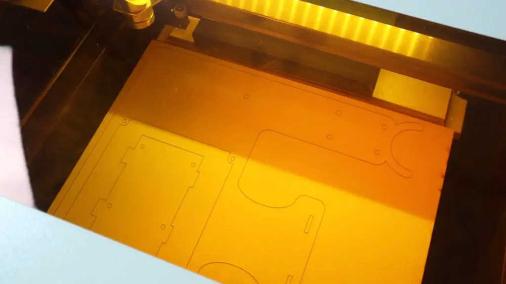
Again, I cut this stand out on my laser cutter from 3mm acrylic, this time clear.
Now that we’ve got our stand components made, lets start putting them together.
I’ll start by mounting the reservoir, pump and radiator onto the stand.
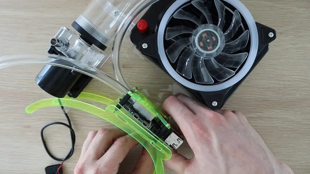
Next, I need to glue the Raspberry Pi stand components onto the main cooling water stand. I clamped the components in place and allowed the cement to cure for a couple of hours before trying to mount the Pi.
Once the glued had properly cured, I put two lengths of tubing onto the heat sink so that I didn’t have to try push them on in the tight space between the Pi and the pump, and then mounted the Pi onto the stand using four nylon M3 nuts on the bottom of the standoffs.
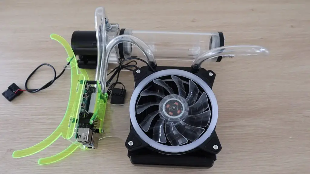
I then added the fittings and finished off the tubing.
One side of the cooling block goes to the pump and the other to the radiator. We also need a section of tube from the radiator to the top of the reservoir.
The last thing to do is to add a small acrylic block to the base of the pump to hold the weight of the pump and reservoir. The legs on the stand are not strong enough to support all of the cooling components and I didn’t want to make them bigger as I like the look of the thinner sections. You’ll also hardly notice the block under the pump if it’s clear.
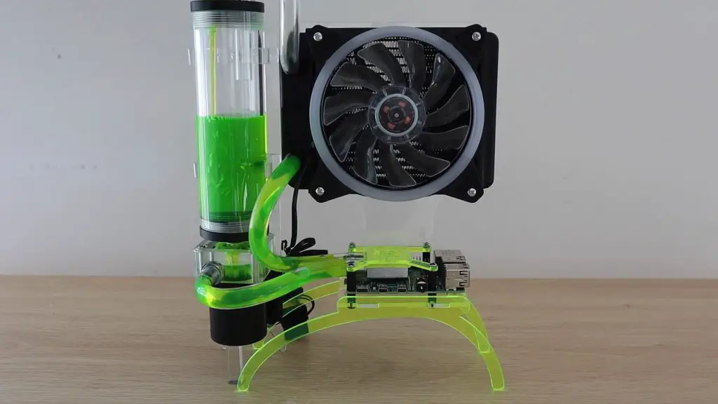
Our water cooled Pi is now complete, we just need to fill it up with water or cooling liquid and try it out. The system took around 300ml of cooling liquid to fill.
Testing The Water Cooled Raspberry Pi 4
The fan and pump are actually quite quiet when running, the system is a lot quieter than some of the small case fans I’ve used on a Raspberry Pi.
Now let’s try and do a stress test on the water cooled Raspberry Pi to see how well this cooling system works.
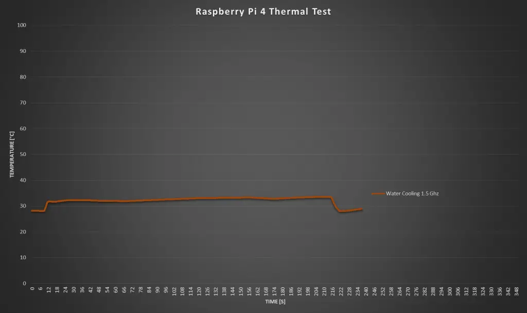
CPU Test At 1.5GHz
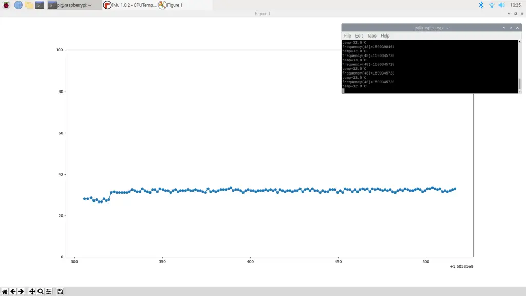
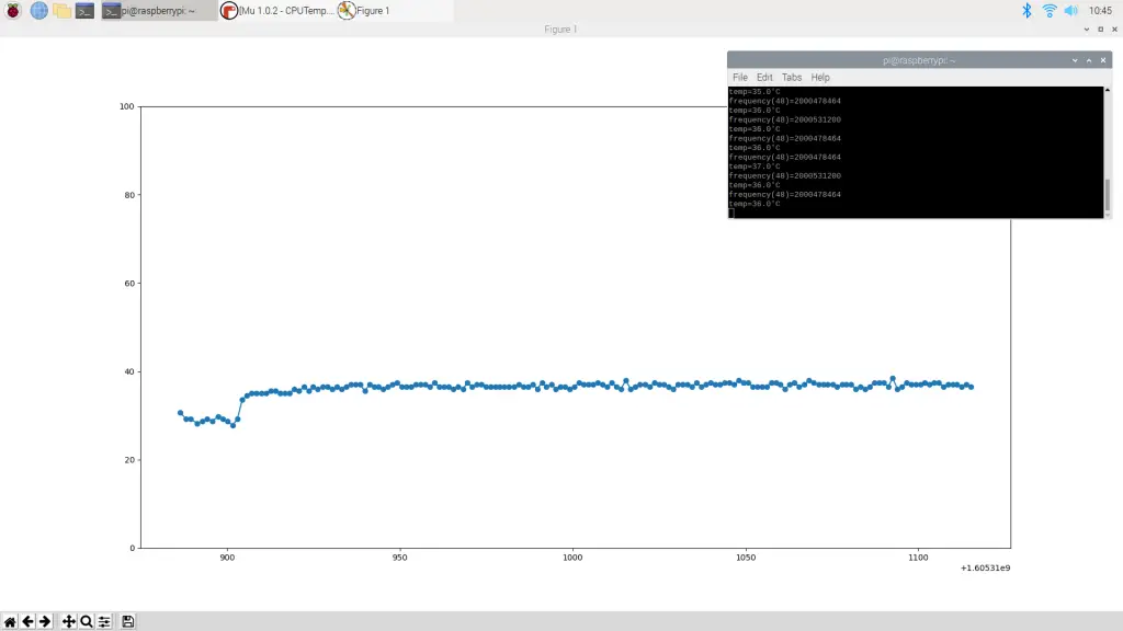
With the CPU clock frequency set to the default 1.5Ghz, we start out with a temperature of around 28°C. This was in a room of around 25°C, so it was done with quite a warm ambient temperature.
I then did a 5-minute stress test at full CPU load.
There was a small spike initially where the temperature went up to 31°C but it stayed between 31°C and 33°C for the rest of the test and dropped off quickly when the test was stopped.
Here’s a graph of the CPU temperature for the duration of the test.
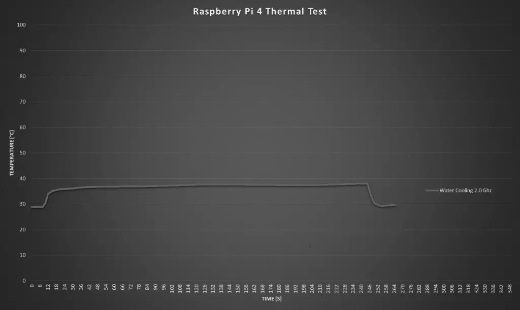
CPU Test At 2.0GHz
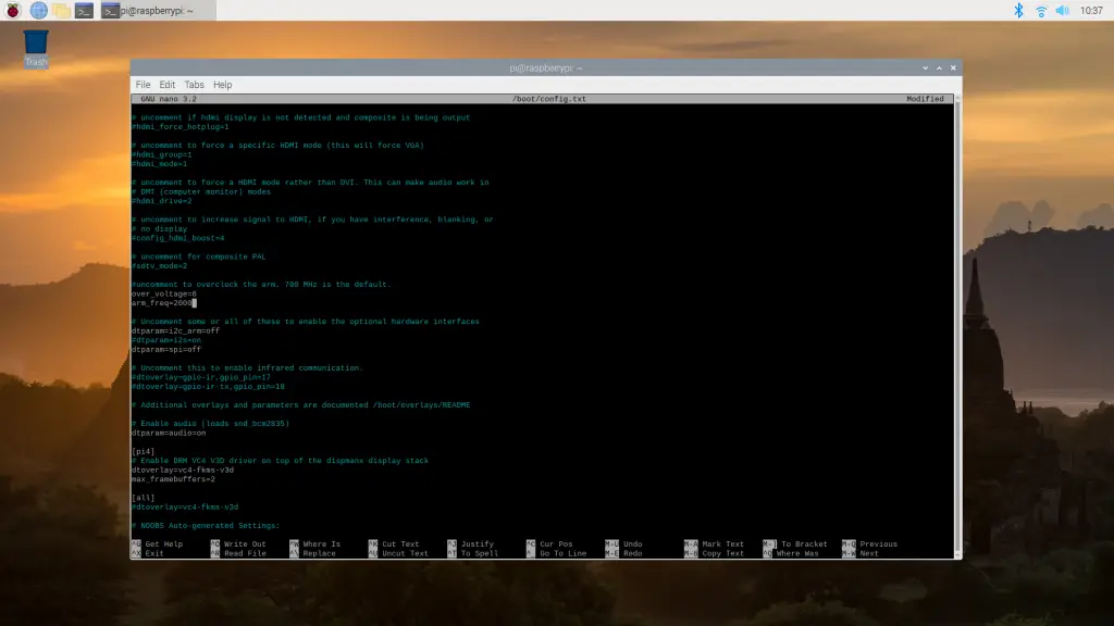
Now I’m going to try overclocking the Pi to test it at a higher CPU frequency.
I set the CPU frequency to 2.0Ghz for this test.
Let’s try doing a stress test and see what we get.
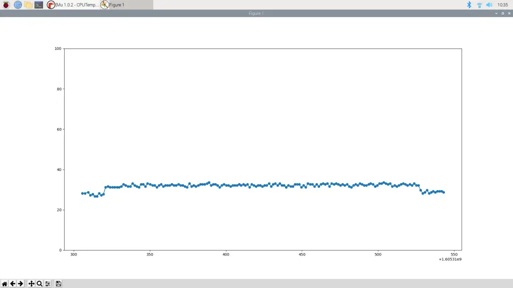
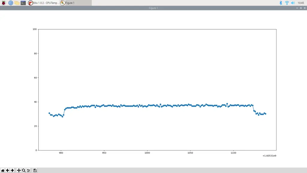
For this test we started out with a temperature of around 29°C, which then quickly spiked to 39°C when the test was started.
The temperature the stayed around 36°C to 37°C for the rest of the test.
Here’s a graph of the CPU temperature for the duration of the 2Ghz test.
Conclusion
The water cooling system on this Pi works really well at keeping the CPU cool. Even when overclocked to 2.0Ghz, the Raspberry Pi 4’s CPU temperature never went above 40°C. I wasn’t able to test the Pi at the maximum 2.147Ghz as my Pi wouldn’t boot up at this frequency, probably due to under-voltage. I’ll try and get this fixed and do a test at the maximum frequency as well at some stage.
To get an idea of whether this is worthwhile, I’m going to be comparing this water cooling system to an Ice Tower, a standard acrylic case and fan and then just a Pi with a static heat sink on it in the next week or two. So make sure that you check back here, or subscribe to my Youtube channel and turn on notifications so that you don’t miss out on that.
Let me know what you think of this water cooled Raspberry Pi 4 in the comments section below!
Pi-hole is a clever piece of software which acts as a network-wide ad blocker. It enables you to block ads on websites, ads in apps on your mobile devices and even on your smart TV, regardless of the software they’re running and without the need for any other local software on the device. Pi-hole also improves your network speed, because the ads are blocked before they are downloaded. This also saves data if you’re on a limited data plan.
A web interface lets you interact with your Pi-hole and view stats on your network traffic.
Now that you know what Pi-hole is, let’s have a look at how to to set one up on your home network, step by step.
If you’re running a large network with lots of users and traffic then the best device to use would be one of the Raspberry Pi 3 or 4 models with an ethernet connection to your router. But for a smaller home network with less than 50 devices and only a couple of users online at a time, a Pi Zero W works perfectly.
I’ve been using one for a month now.
Here’s a step by step video guide to setting up your Pi-hole, read on for the written guide:
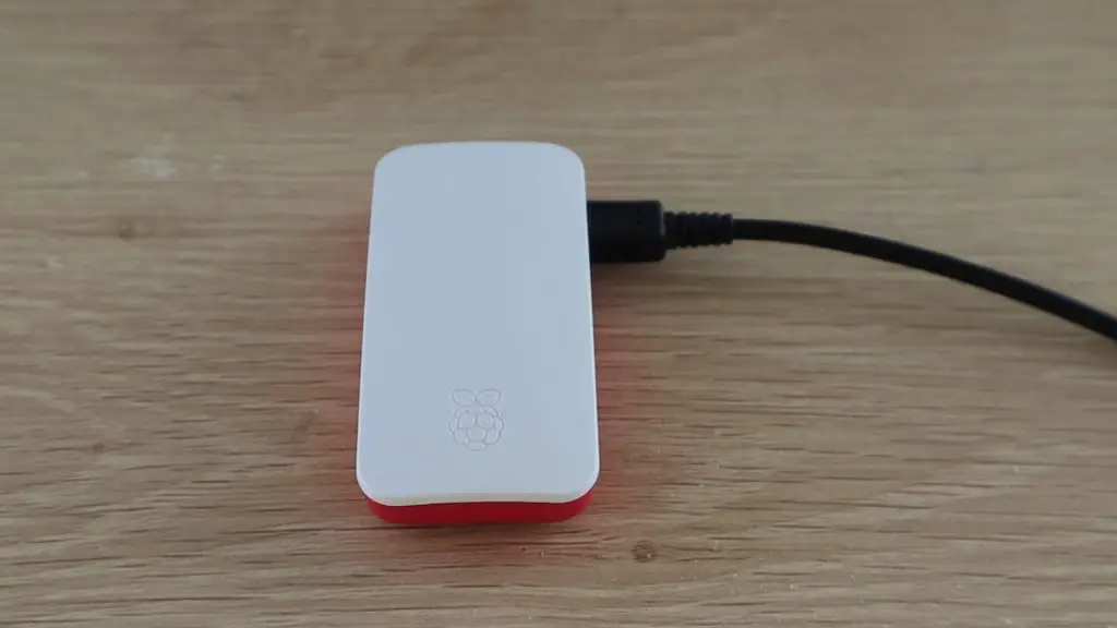
You’re going to need a Raspberry Pi Zero W, a micro SD card of at least 16GB, and something to put the Pi into to protect it, I just used the official case. You can usually buy these kits online for around $30-$50 dollars which includes everything you need, even a power supply, although you can buy the Pi alone for as little as $10 if you do some searching.
You won’t need a mouse, keyboard or monitor for this as we’ll be using another computer on the network to set up the Pi-hole.
Preparing Raspberry Pi OS Lite On The SD Card
We’ll start by preparing the Raspberry Pi’s operating system on the SD card, Pi-hole will then be installed to run on this operating system later.
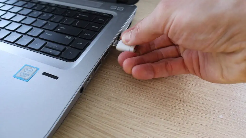
Plug your microSD card into your computer. Don’t worry about formatting it just yet, we’ll get to that in a minute.
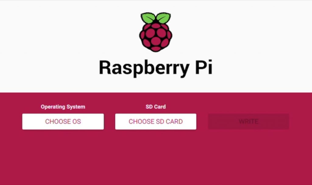
Start by downloading the Raspberry Pi Imager on your computer. This is a fairly new tool and it’s one of the easiest to use. They have a version for Windows, Mac and Linux.
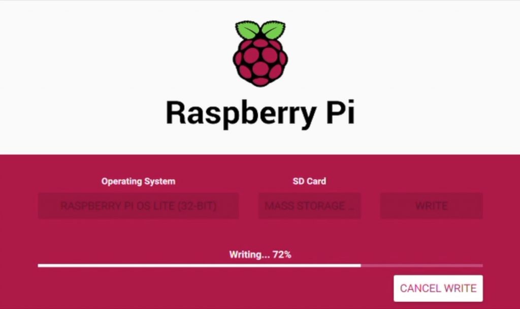
You just select the Raspberry Pi operating system you need, which in our case is Raspberry Pi OS Lite, and then select the SD card you want to write the image to. Click write and let the tool do the rest, it’ll write the image, check it and then eject the SD card.
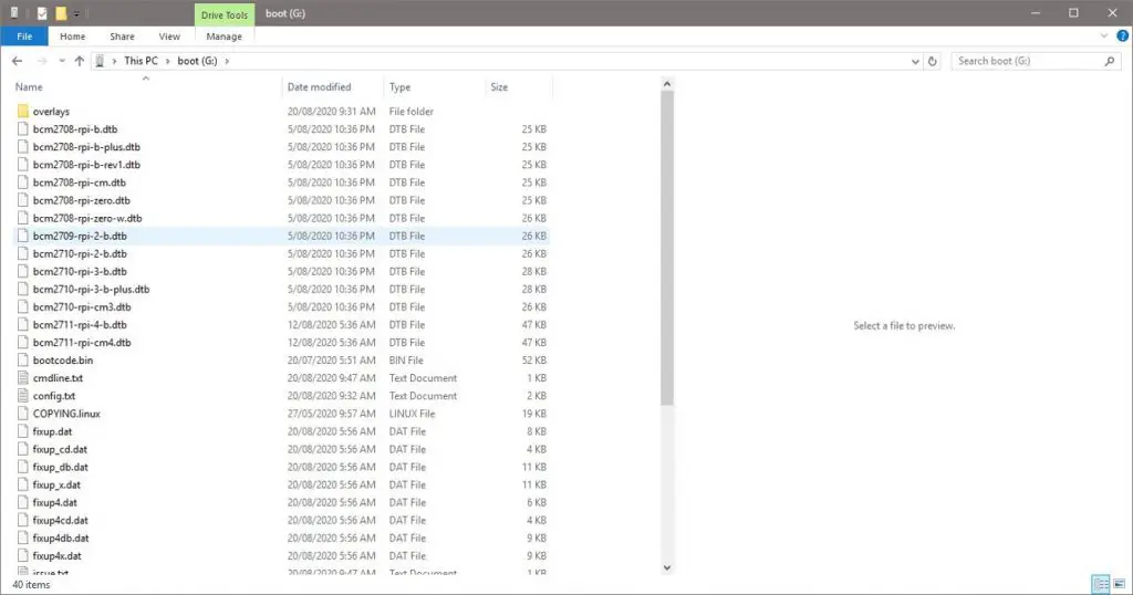
There is a bit more to do on the SD card before we’re done on the computer, so you’ll need to plug it in again to access it. You might get a couple of windows pop up and one which says you need to format the card in order to use it, just ignore these and close them. Don’t format the card again.
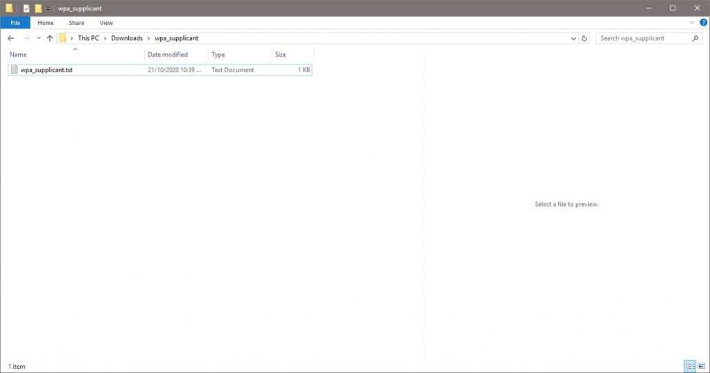
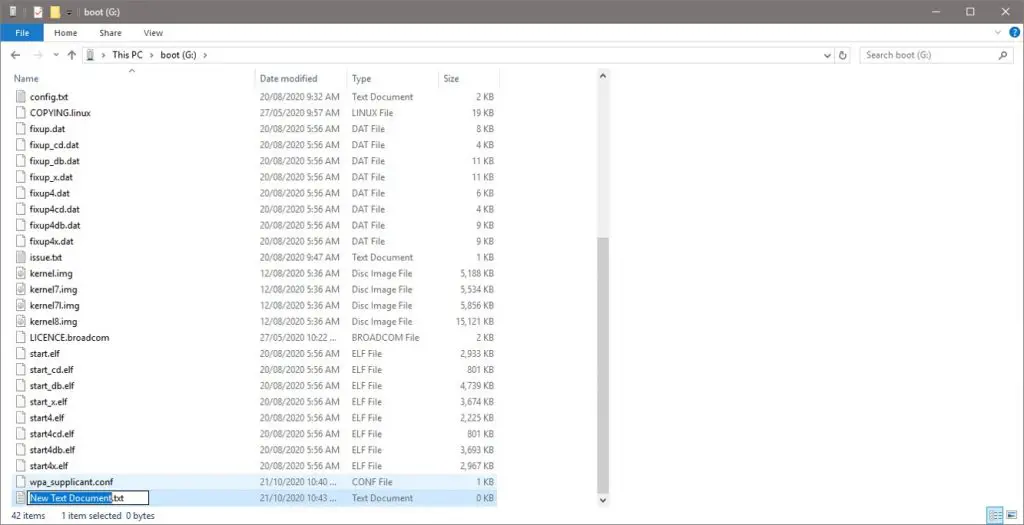
The will be one readable partition on the card called boot, you should be able to open this partition and you’ll see a number of files. We need to add two files to this directory, one to tell the Pi how to connect to your network and another to enable SSH so that you can access it over the network.
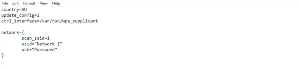
Download the network settings template wpa_supplicant and open it using a basic text editor like Wordpad.
In the network settings section, you need to add your local WiFi network name next to ssid and your network password next to psk, leaving all of the punctuation marks in place. You can also change your country code at the top if you’d like, this can be set up later though.
Save and close the file.
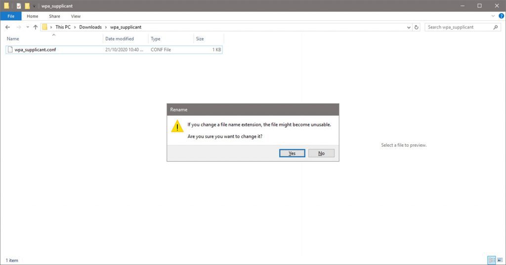
Now change the extension of the file from .txt to .conf. Click yes if you are given a warning.
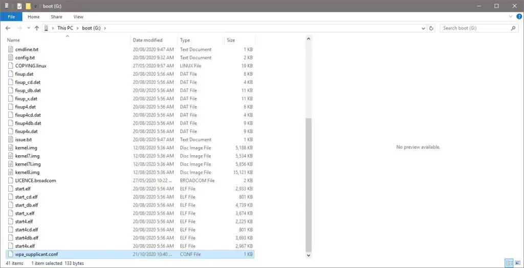
Now copy this file into your boot directory.
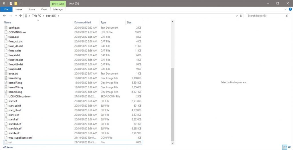
Thats the first done, now we need to add an SSH file.
Create a new text file and change its name to ssh and remove the extension. So the file should just be a blank file called ssh with no extension.
Once you’ve got both of these files then you can eject and remove your SD card.
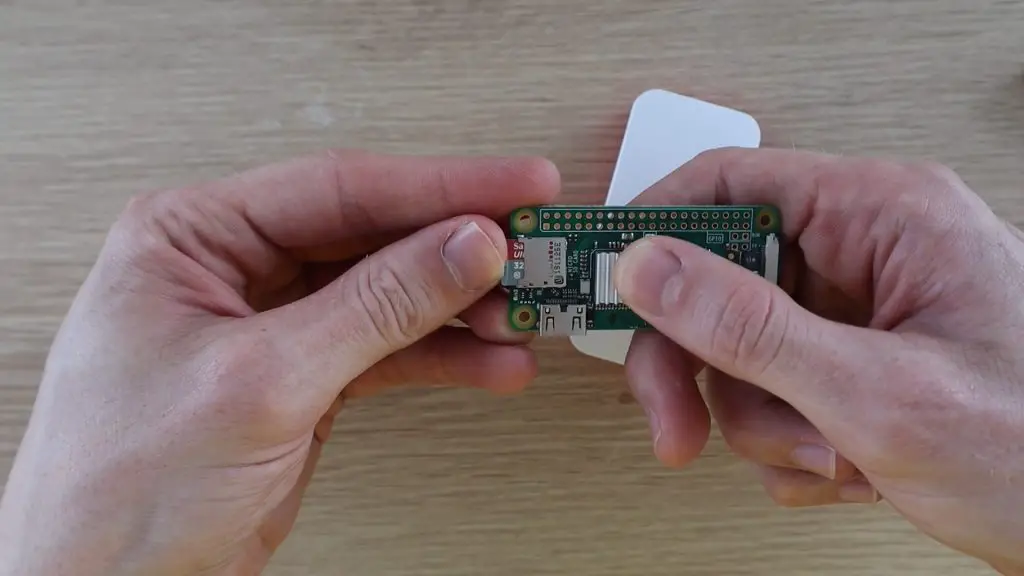
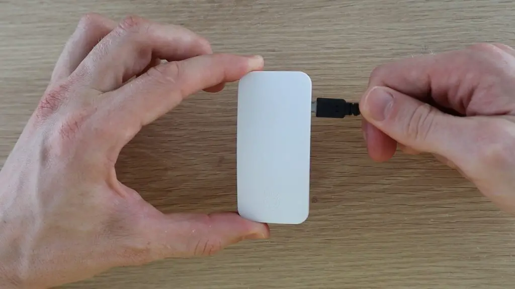
Plug the SD card into your Pi, then put it into it’s case and plug the power cable in. It’ll take a few seconds to boot up.
First Boot & Connecting To Your Pi Zero W
Finding Your Pi’s IP Address
Now that you’ve got your Pi booted up and (hopefully) running, you need to be able to access it in order to install Pi-hole onto it and make any settings changes or updates.
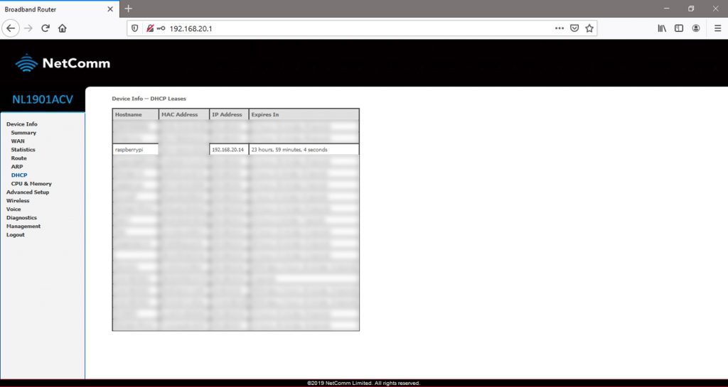
To do this, you first need to figure out your Pi’s IP address, which has been assigned by your router. There are many ways to do this, one of the easiest is by logging into your routers admin page. You’ll need to do this later anyway to make a few changes to your router’s settings. There are often details on how to login to the admin page, along with the default username and password, on the label on the router.
Depending on how complex your router’s software is, you may need to do some exploring until you find a page which lists all of the devices currently connected to the network along with their IP address, this is usually called a DHCP table. Take note the IP address assigned to your Pi.
While you’re logged in, you need to set this IP address (or another one if you’d like) up as a static IP address, so that your router always assigns this same address to your Pi-hole, this is an important step, you’ll see why in a bit. Again, all routers are a bit different, so you’ll need to do some digging if you don’t know how to set up a static IP on yours. If you can’t find the option, try googling your Router’s model and the words “static IP” and you should find some information.
You’ll typically need your Pi’s MAC address, which should also be listed in the DHCP table, and the IP address which you want to use. Enter these to assign your chosen IP address to your Pi each time it joins the network. If you choose a different one to the one currently assigned then you might have to reboot the Pi after this step.
Now that you’ve got your Pi’s IP address, you can access it over the network.
Connecting To Your Pi Over The Network
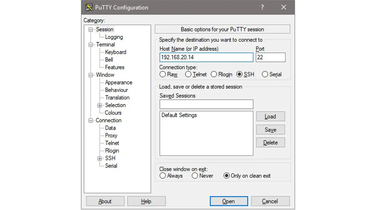
You’ll need to install a terminal emulator / SSH client like Putty to access your Pi’s terminal.
Enter your Pi’s IP address and then click open to attempt to connect to the Pi.
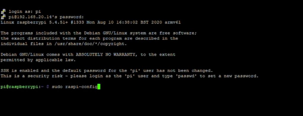
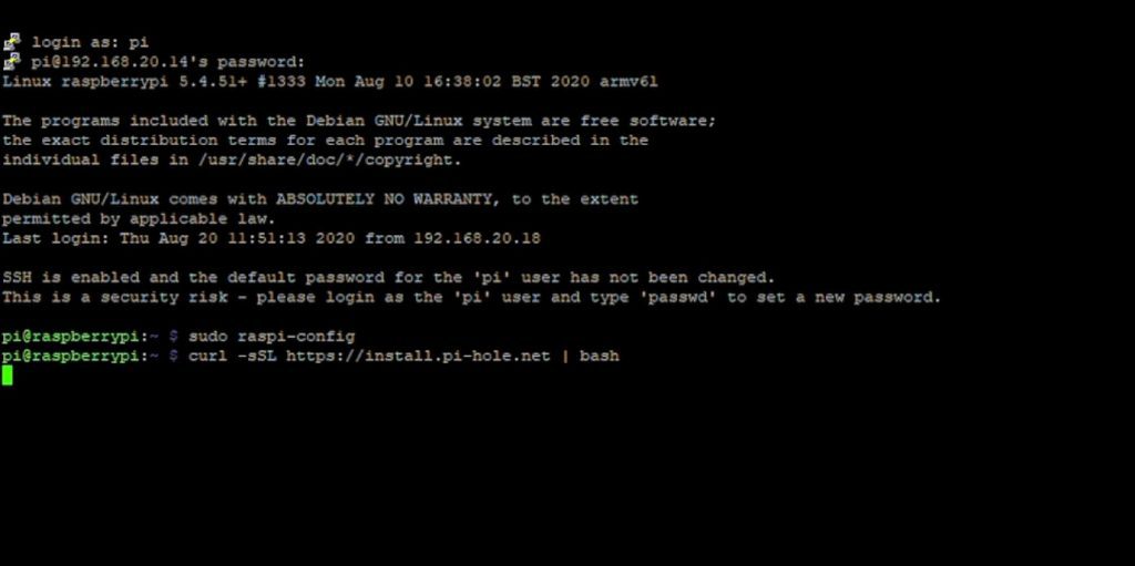
You’ll get to a black terminal display that asks you for a login. The default username is “pi” and the password is “raspberry”.
You’ll want to change these as soon as possible. So it’s a good idea to run the configuration tool first by entering:
sudo raspi-config
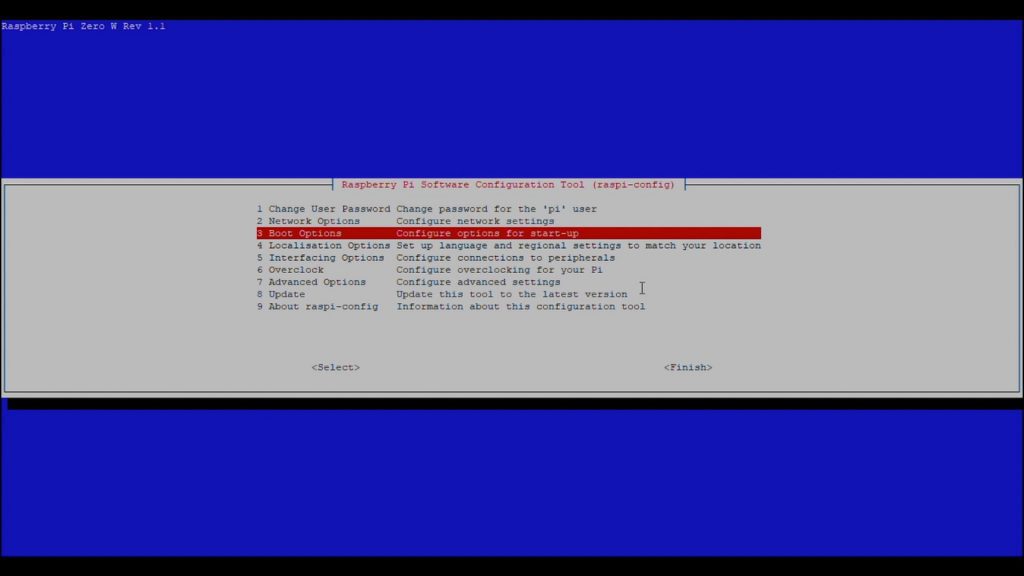
This tool lets you change a number of settings on your Pi.
As a start, you should change:
The default username
The password
Make sure that you’ve got the correct regional settings selected.
Installing Pi-hole On Your Raspberry Pi Zero W
Now you should have your Raspberry Pi Zero set up properly with a new username and password and connected to your network, with access to it over SSH.
Now you can install Pi-hole by entering the following command:
curl -sSL https://install.pi-hole.net | bash
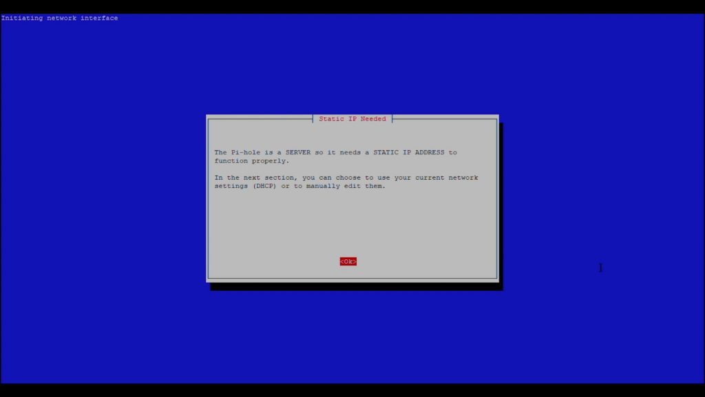
The Pi will start downloading and installing the software. It takes a couple of minutes to run through and you’ll then get to the following page to guide you through the Pi-hole setup.
For the most part, you can just run through the default selected options and hit OK for each. You shouldn’t make any changes to these settings unless you know what you’re doing or you’ll likely just land up with a Pi-hole that doesn’t work.
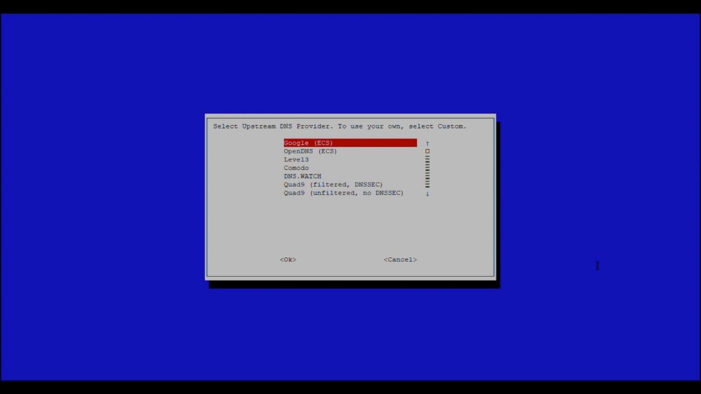
You might want to change your Upstream DNS provider if you’d like. This is just the provider which your Pi-hole is going to use as the name server for your domain requests.
Also, make sure that the IP address listed is the one which you set as the static IP for your Pi.
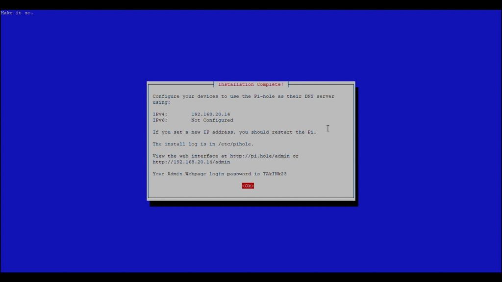
It’ll then run through another setup process and you’ll finally get to an “installation complete” display. Take note of the Admin Webpage password as you’ll need this to log in to the Pi at a later stage to view the detailed statistics and to change any settings. You’ll be able to change this password from the web interface – but you need this password in order to do so.
You can change your Pi-hole password at a later stage over SSH using the command:
sudo pihole -a -p (new password)
You can now close the terminal connection.
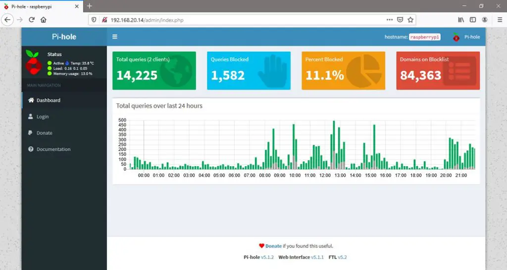
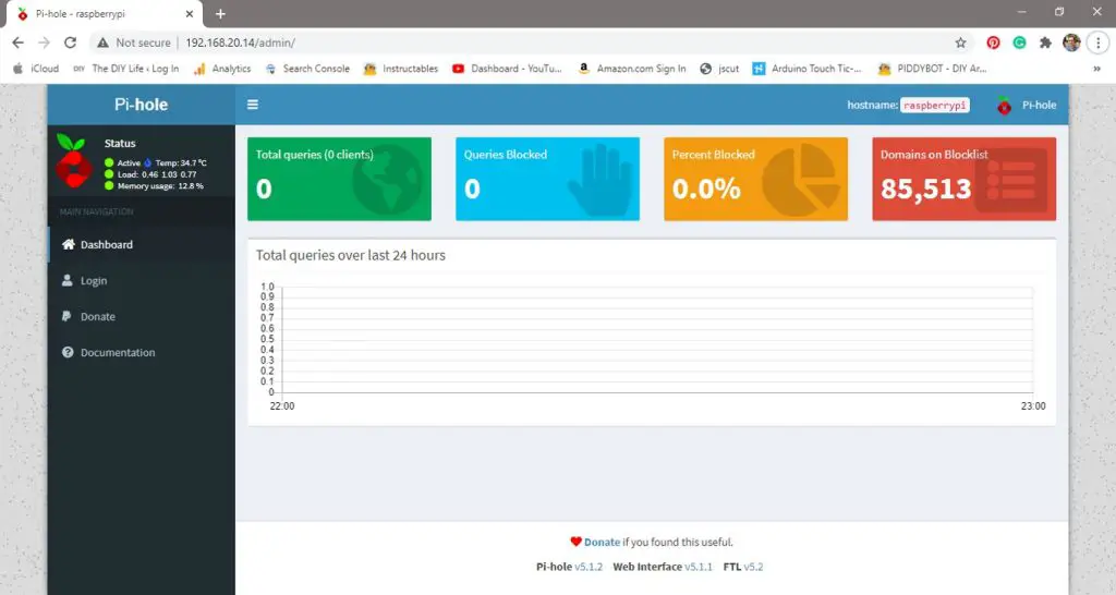
Test if Pi-hole is running by going to your browser and typing in the IP address that you’ve configured for your Pi along with forward slash and admin.
192.168.20.14/admin
You should see a page like this show up. You’ll notice that no queries have been received or blocked yet because the router isn’t directing traffic through the Pi-hole, there is still one last thing to set up.
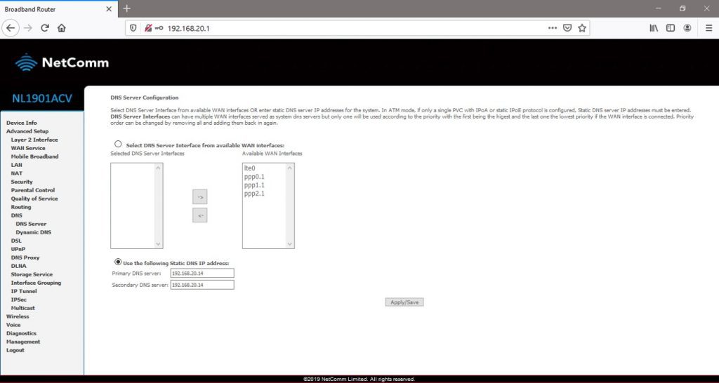
Setting Up Your Router To Direct DNS Requests Through Your Pi-hole
You’ll need to log back into your router and find your DNS settings page.
Here you’ll need to set your Pi-hole’s IP address as the primary DNS server, if your router has to have a secondary DNS server, then type the same address into that field as well. Click save or apply to make the changes. You may then need to reboot your network devices to take effect.
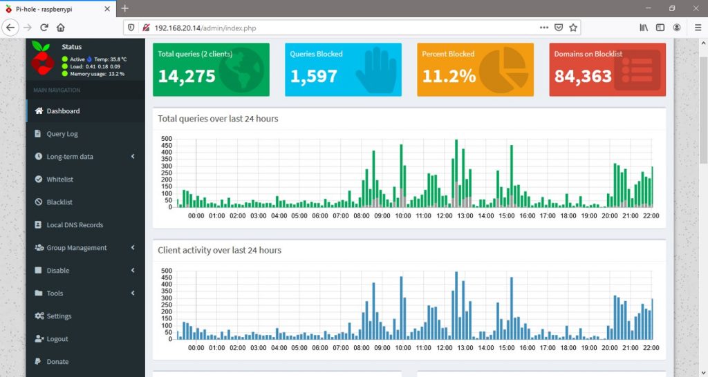
If you go back to your Pi-hole dashboard, you should now see requests coming through and ads queries being blocked.
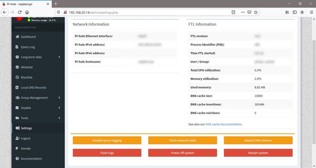
If you log in to your Pi-hole using the admin password that was created during setup, you should have more access to the network statistics and see detailed logs.
You’ll also be able to change settings, add or remove domains on the block list, and reboot or turn off your Pi.
Remember that if you turn off your Pi and your router’s primary and secondary DNS server are set to your Pi’s address, you will no longer have access to the internet until your Pi is back online. So make sure that your Pi-hole is on a reliable power source, preferably the same one as your router.
Some routers have a USB port on them which has enough power to supply an external drive. This port usually supplies enough power to drive a Raspberry Pi Zero W running as a Pi-hole, so you can ensure that they’re always on together.
This guide is just a starting point to get your Pi-hole up and running, there is a lot more than can be done using Pi-hole once you’re comfortable with it.
You can also set the Pi up to run the DHCP service, which allows the Pi-hole to identify devices by their name rather than IP address and even integrate powerful third-party anti-malware and anti-phishing DNS services.
That’s it, you’ll now be able to enjoy an ad free browsing experience on your home network!
Its worth noting that there are some limitations to the ad blocking ability of the Pi-hole. The Pi-hole is simply blocking requests being made to domains which are known to serve ad content, if the website you are accessing serves its own ad content, from their same domain, then the Pi-hole won’t block these ads. Typical examples are ads running on Youtube videos or Facebook ads in your Facebook news feed.
Let me know if you’ve used a Pi-hole in the comments section.
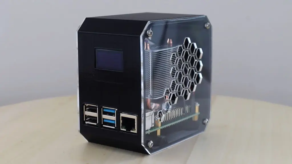
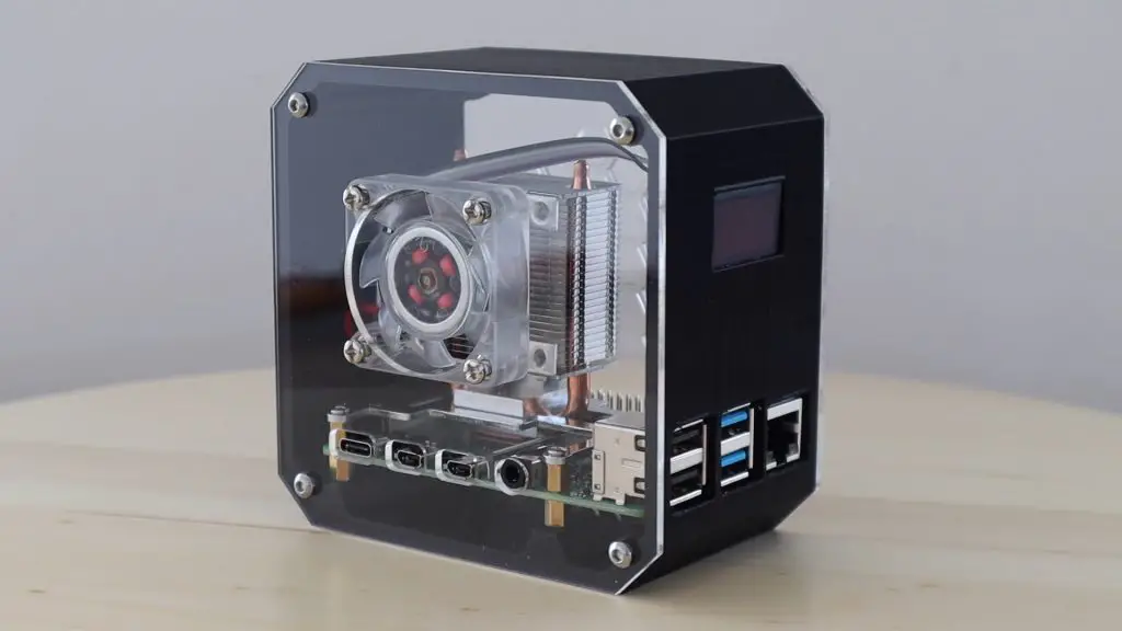
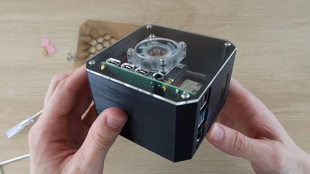
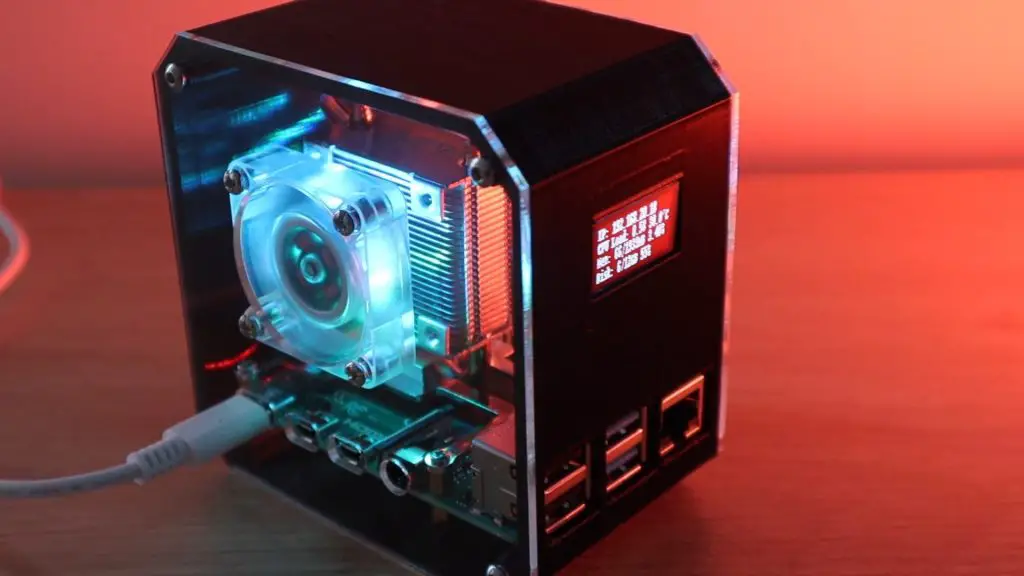
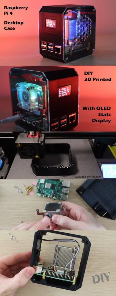
Today I’m going to be showing you how to make your own desktop case for a Raspberry Pi 4, which looks like a mini desktop pc.
The body of the case is 3D printed and it has clear acrylic sides so that you’re able to see into it. I’ve used an Ice Tower to cool the CPU, but have mounted the fan onto the side of the case rather than on the heatsink.
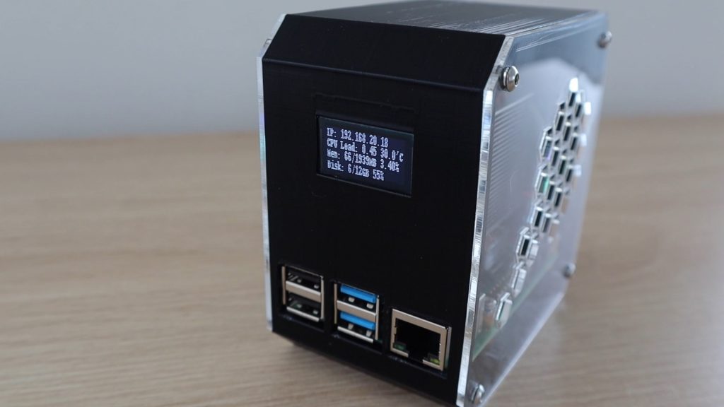
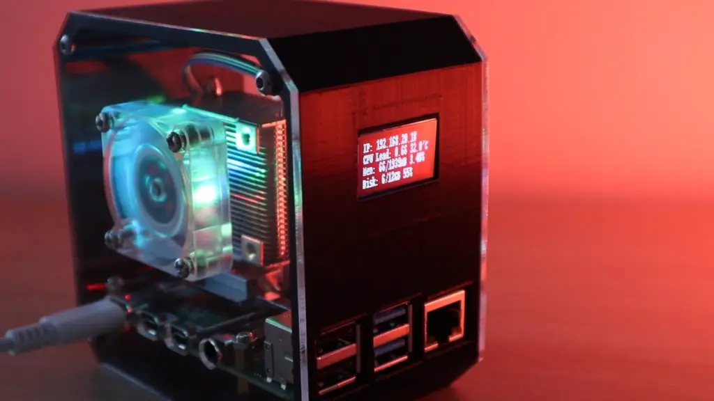
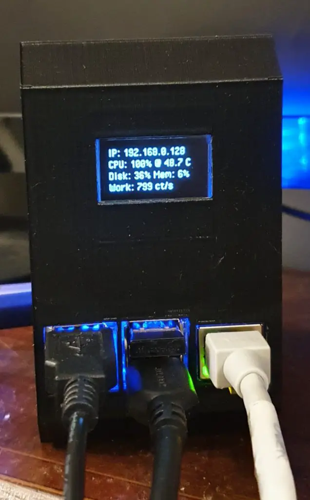
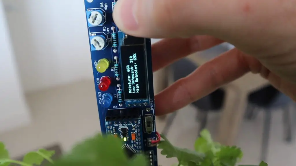
I’ve also included an OLED display on the front of the case which displays the Pi’s IP address and some stats like the CPU, storage and memory usage, and the CPU temperature.
You can now buy a pre-made kit for this Raspberry Pi 4 Desktop Case – Buy Here.
Here’s a video of the build and the case and display in operation:
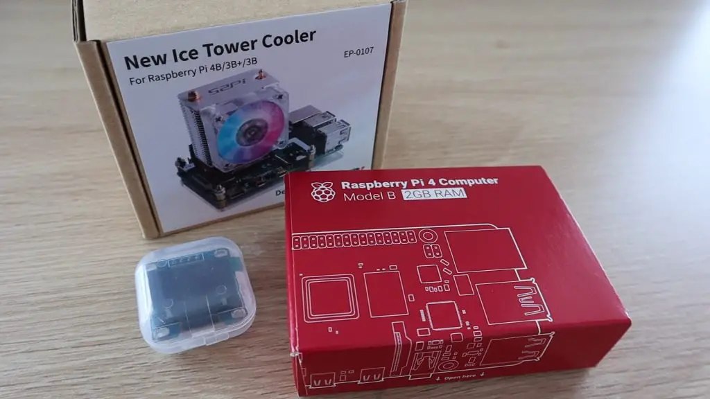
What You Need To Make Your Own Raspberry Pi 4 Desktop Case
You don’t need a laser cutter for this build, although it does help significantly with making the sides. You can also use an online laser cutting service or simply cut your own sides using hand tools. I’ve used a Desktop K40 laser cutter/engraver.
Note: The above parts are affiliate links. By purchasing products through the above links, you’ll be supporting this channel, with no additional cost to you.
Making The Raspberry Pi 4 Desktop Case
3D Printing The Body
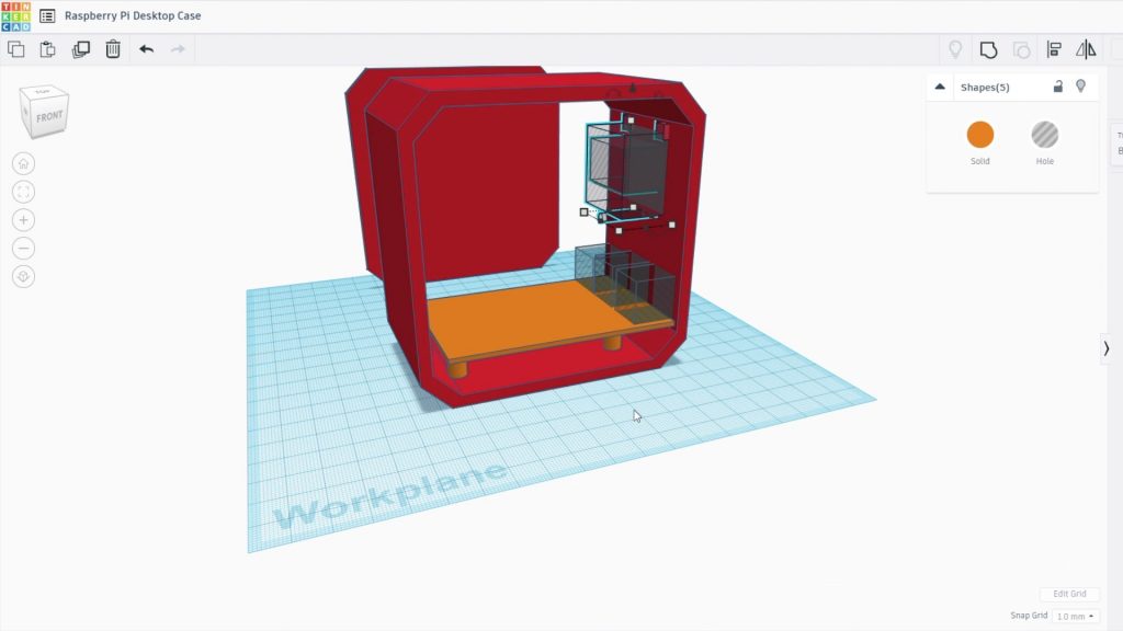
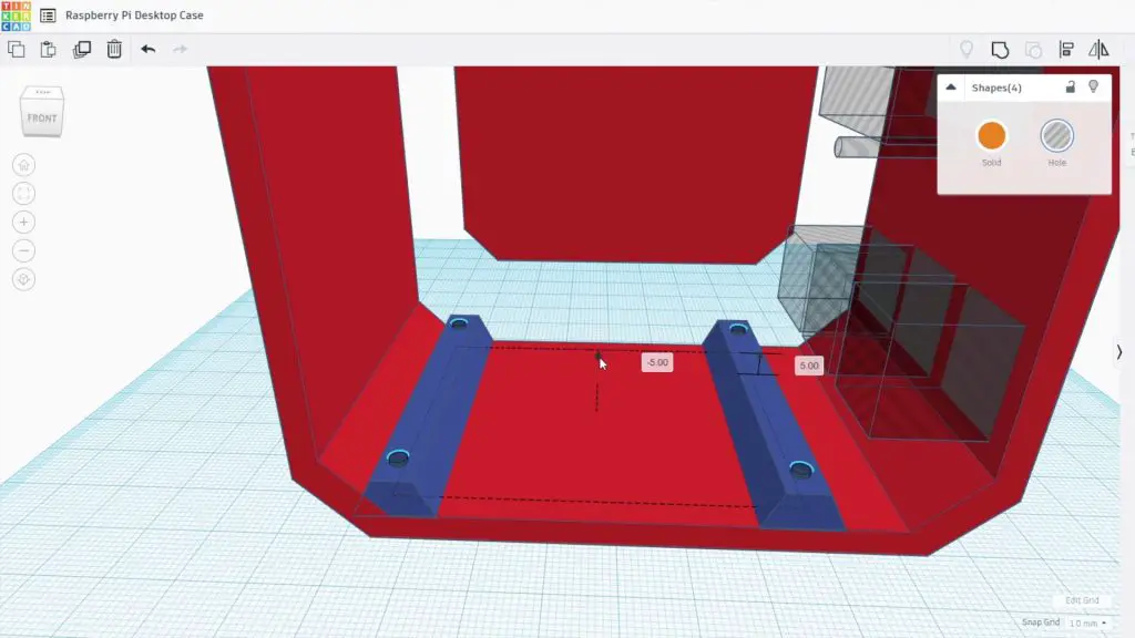
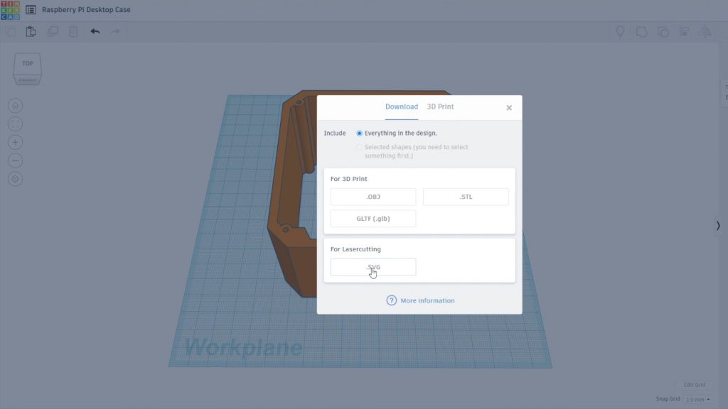
I started out by designing the 3D printed body of the case in Tinkercad.
Note: This design is copyrighted and is available for your personal, non-commercial use only. It may not be reproduced for commercial gain or republished in any form.
I’ve also put together a pack with some additional case variations which is available through this link – Additional 3D Print Files. This pack includes:
Case With SD Card Cutout
Case With OLED Display On The Other Side (USB & Ethernet Ports On Back)
Case With No OLED Display Cutout
Additional Side Panel Design With Larger HDMI Cutout
I drew a rough outline of the case and then positioned the Raspberry Pi within the case so that the USB and Ethernet ports are available through the front and the Power, HDMI, and audio ports are accessed through the side panel.
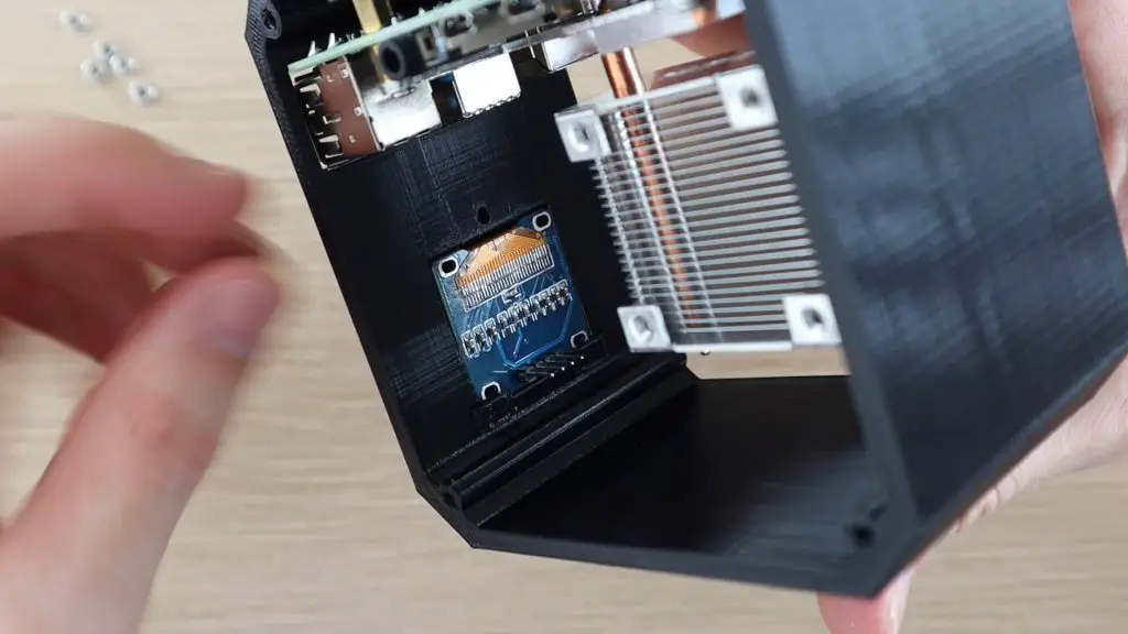
The OLED display is positioned on the front of the case above the ports. The OLED display will be held in place with two small clips on the top edge and a screw with a plastic clip at the bottom, a design which I’ve used before on my Arduino based reaction timer.
The Pi is going to be mounted onto the brass standoffs which came with the Ice Tower, so I added some holes to accommodate the M2.5 threads.
I don’t remove the SD card on the back of the Pi very often, so I didn’t add a cut-out for it. If you do, then just add a circular cut-out to the case at the back so that you can still access it. It is going to be a bit of a chore to swap the SD card if you don’t have this cut-out as you’ll need to remove the Pi from the case to access it, I’m happy with doing this if I ever need to change the card.
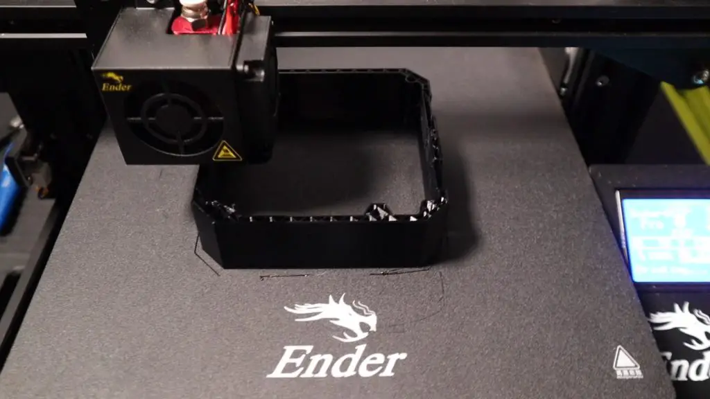
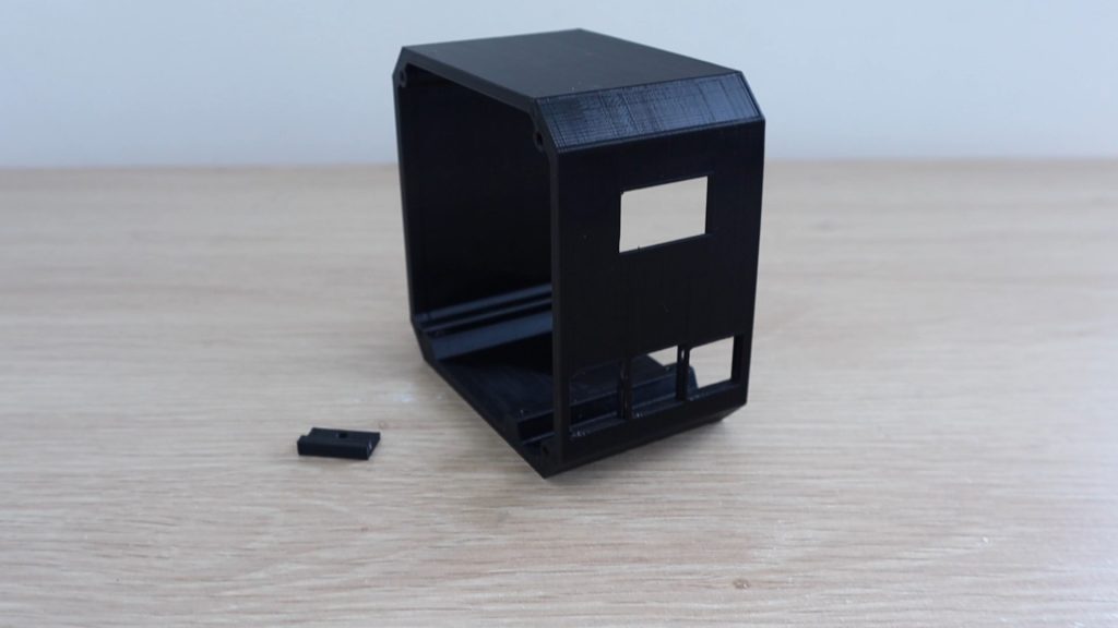
I 3D printed the Raspberry Pi 4 Desktop Case using Black PLA with a 0.2mm layer height and 15% infill. I also added print supports for the cutouts for the display and ports on the front. You’ll probably need to add these as well, which is easy to do in your slicing software. You’ll also need to print the small plastic display clamp.
Install The Raspberry Pi & Ice Tower
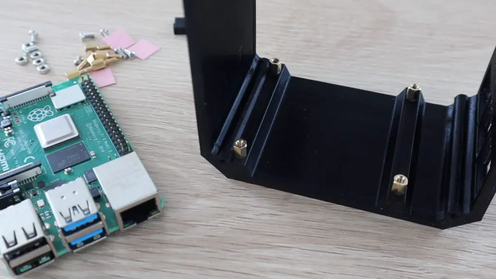
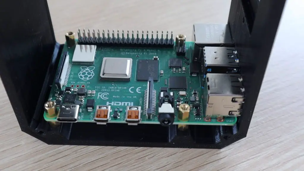
Now that the main body of the case is complete, let’s mount the Raspberry Pi into it. Start by screwing the brass standoffs into the holes in the base.
The holes for the brass standoffs are intentionally quite tight the first time you screw them in. You’ll likely need to use a small wrench or spanner to get them screwed in, you can also use some needle nose pliers if you don’t have a suitable size wrench.
I’ve just changed the orientation of the screws and standoff mounts supplied with the Ice Tower so that they screw straight into the bottom of the case and don’t require and through holes. If you follow the Ice Tower installation manual, you’ll notice that the standoffs and screws are installed the opposite way around.
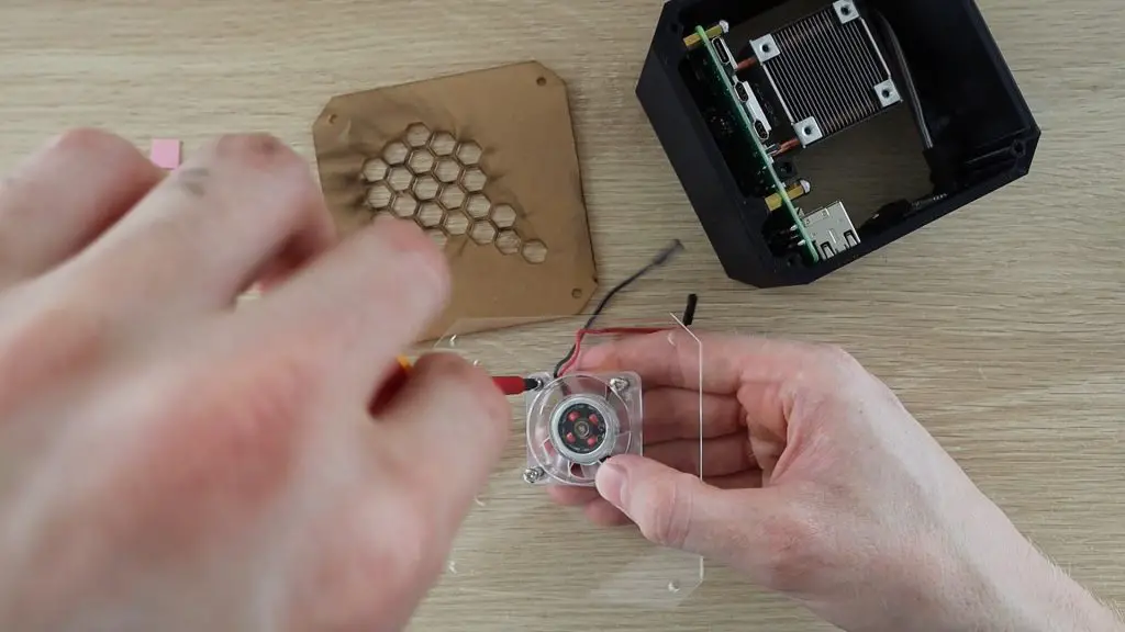
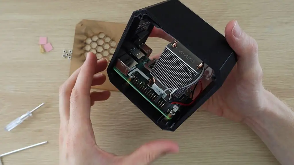
Next, we need to remove the fan from the Ice Tower so that we can attach it to the acrylic side panel. By moving the fan onto the side panel, we make sure that cool air is being drawn in from the outside of the case and then has to leave from the exhaust air vents on the opposite side.
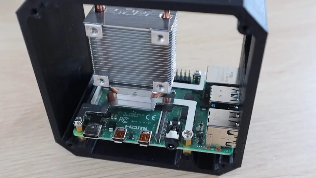
Add the support brackets to the bottom of the Ice Tower heatsink as per the instructions. Make sure that you follow the correct orientation of these.
Update – As a few people have pointed out, it’s easier to install the OLED display and the screw to hold it in place before putting the Ice Tower in.
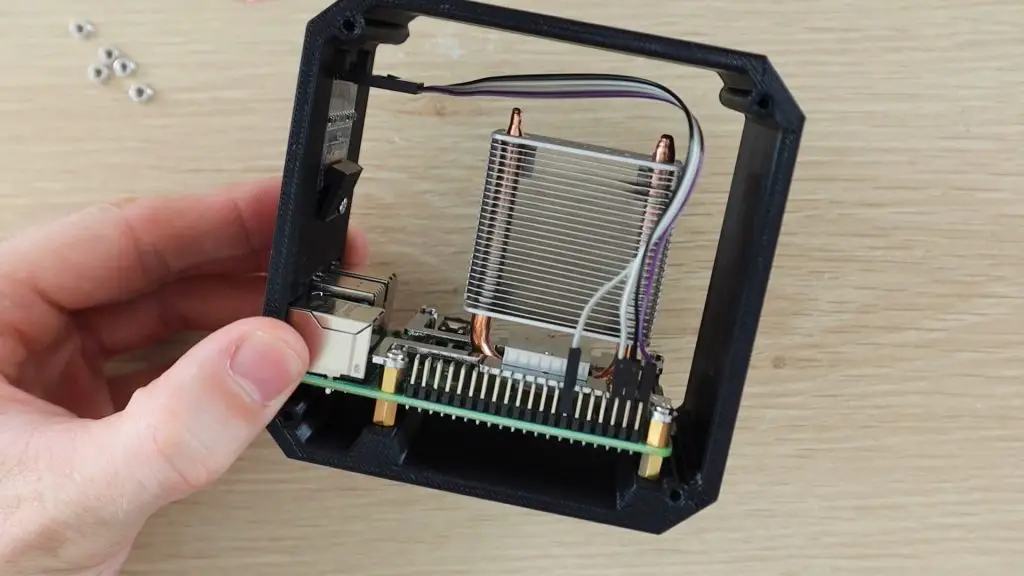
Place the Raspberry Pi into position and then use the second set of brass standoffs, screwed into the bottom set, to secure it.
Stick the heat sink pad onto the Pi’s CPU and peel off the top layer of protective film. Position the Ice Tower heat sink onto the heat pad on the CPU and then secure it with the four screws into the brass standoffs.
Install The OLED Display
Now we need to install the OLED display onto the front panel. If your display came without the pins soldered into place, solder them onto the back of the display.
Slide the top edge of the display in under the plastic clips and then gently push it down into position in the cut-out.
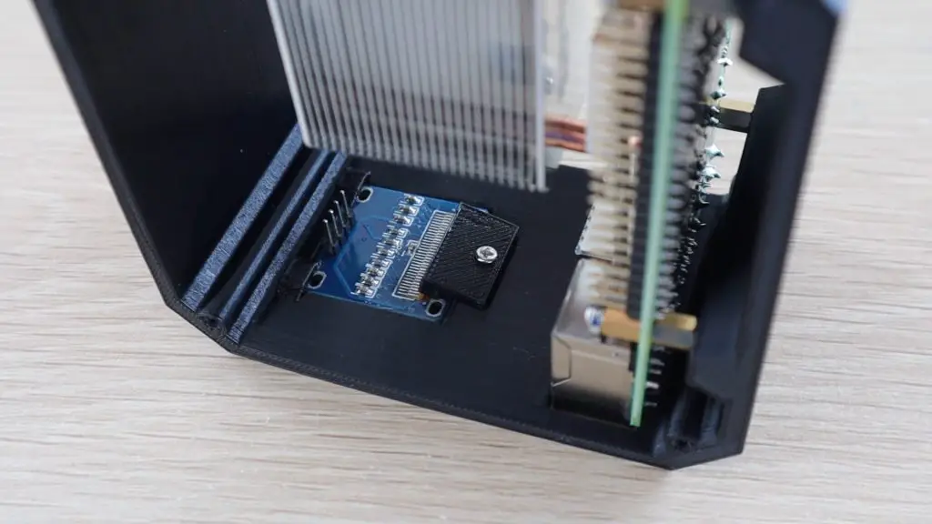
Use the 3d printed clamp to hold it in place with a small screw. You might need a flexible shaft or 90-degree screwdriver to tighten the screw.
Don’t over-tighten the screw, the clamp just needs to gently hold the display in place. If you clamp it too tightly you might crack the glass on the display.
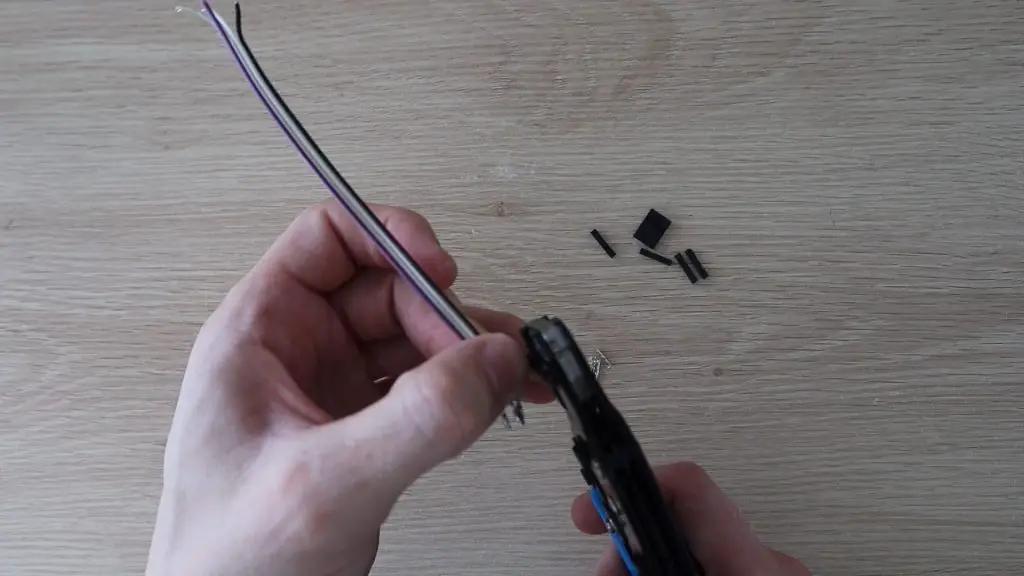
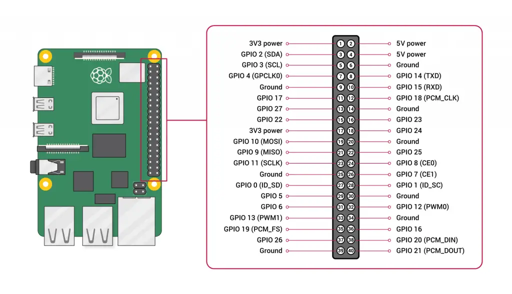
Now we need to prepare the wiring to the OLED display. You’ll need to make 4 connections to your GPIO pins, two for power and two for communication. I made up this short connector cable using some DuPont connectors and some ribbon cable. You can also use some female pin header strips or female breadboard jumpers to connect the display to the Pi.
Once your cable is made up, connect it to the back side of the display and then plug the leads into the GPIO pins as follows:
GND to Pin14 Ground
VCC to Pin1 3.3V Power
SCL to Pin5 SCL (GPIO 3)
SDA to Pin3 SDA (GPIO 2)
I’ve noticed that there are two versions of these OLED displays available and they have the power pins the opposite way around, one version has VCC and then GND and one GND and then VCC, so just make sure that you’re connecting power the correct way around for your display.
Make The Acrylic Sides
The internal parts of the case are now mostly done, so let’s make up the acrylic sides to close it up.
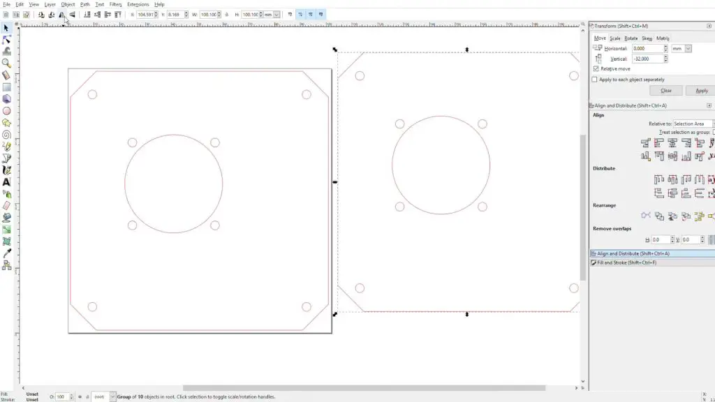
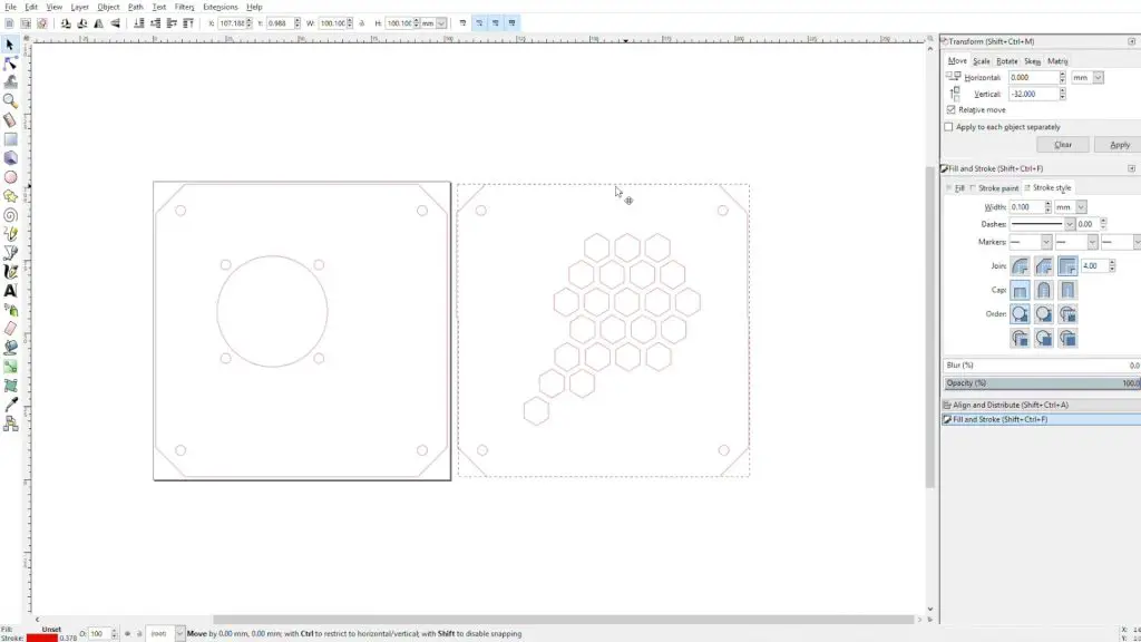
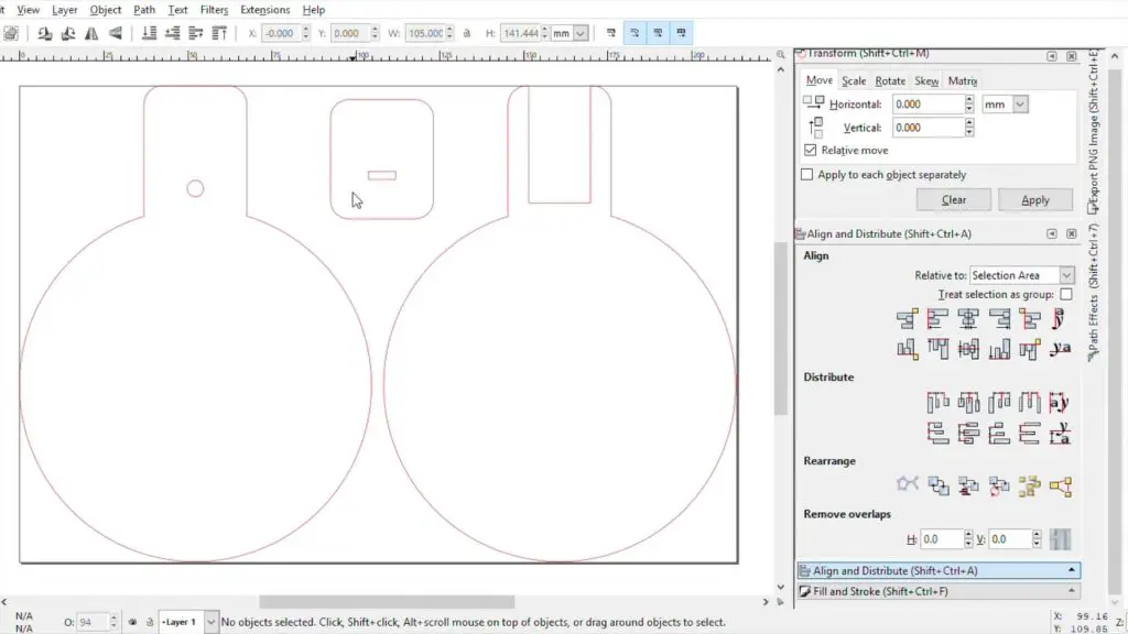
I started in Tinkercad again and positioned a block in the case roughly where the Ice Tower heat sink is going to be so that the holes for the fan are in the correct place on the side panels. I then exported the side profile of the case and heat sink to open up in Inkscape to draw the laser cutting profile.
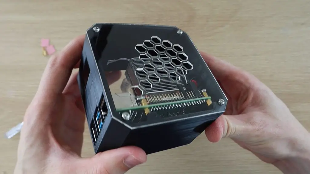
We need two sides, one with the fan for the inlet and one with some holes in it for the exhaust air.
We can remove the inside edge profile as we only need the outline of the case and the screw holes. We need to add a hole for the fan and the four surrounding holes for the fan screws. We’ll also need to add cut-outs for the ports along the side of the Raspberry Pi.
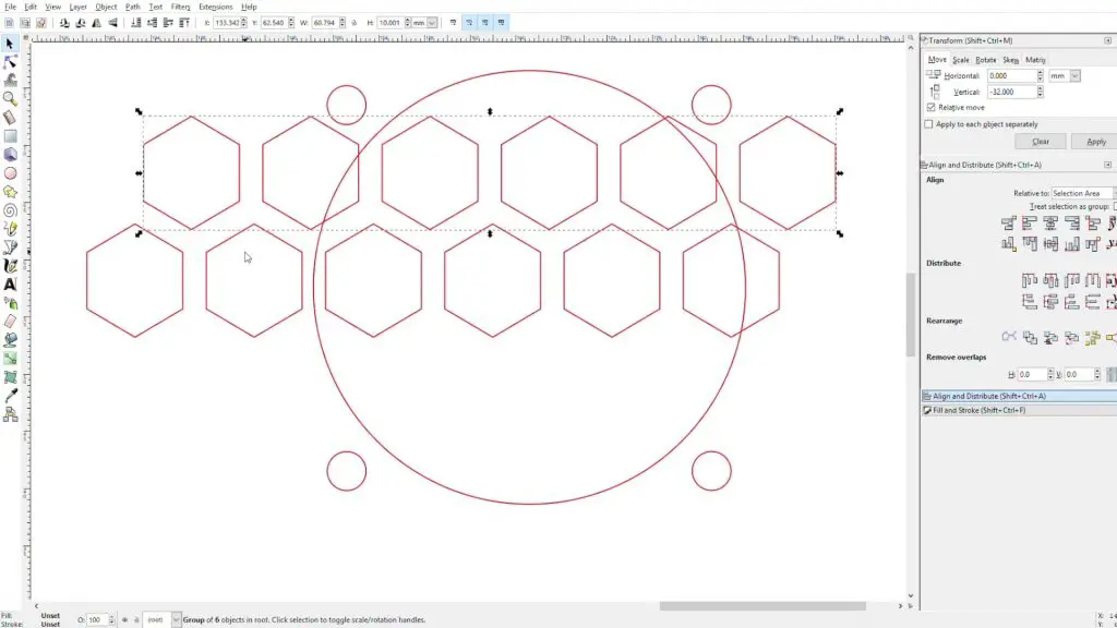
Next, I created a mirror of the fan side to the exhaust side and drew a hexagon pattern for the exhaust airflow.
If you’re not going to be laser cutting the sides and you’re cutting them out by hand, then replace these hexagon holes with circular drilled holes (Ø8mm) in the same area.
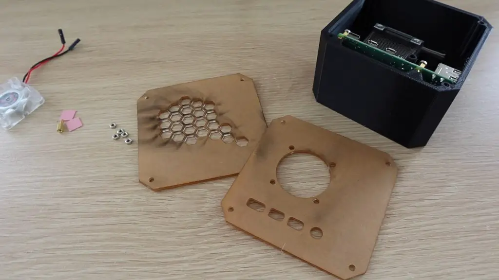
Now let’s get the sides cut out. I used 2mm clear acrylic for the side panels.
You can use a colour tinted or opaque acrylic as well if you’d like. A lot of the coloured sheets are only available in 3mm. This won’t really matter, you’ll just have thicker edges.
To mount the fan onto the side panel, you’ll need to press some M3 nuts into the pockets by the screw holes. It’s easiest to place the nut on a flat surface and then press the fan hole over the nut to push it into place. These are tight so that you don’t need to use a spanner to hold them when you tighten the screws.
If you want to re-use the fan screws, they’ll be too short to fit through the acrylic and fan and then into the nuts, you’ll need to press the nuts into the front (acrylic side) of the fan. You’re relying on the friction between the nut and the fan to hold it in place, but it works fine in this case as there isn’t much load on them.
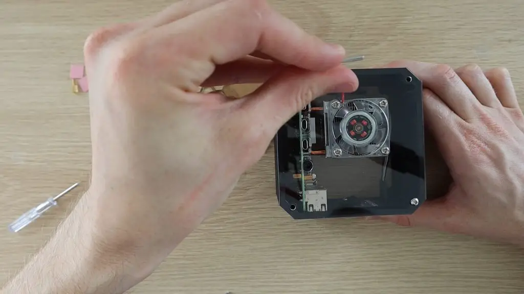
Screw the fan side panel onto the 3D printed case using four M3 x 8mm hex head machine screws.
The screws should be a bit tight as the inside of the holes aren’t threaded, most 3D printers can’t print such a fine thread.
Now plug the fan into the 5V supply on the Pi and then install the other side panel. The red wire to Pin 4 (5V) and the black wire to Pin 6 (Ground).
That’s it for the assembly, the Raspberry Pi 4 Desktop Case is now complete. We just need to get the OLED display working.
To get the display working, we need to run a Python script. You’ll need to boot your Pi up to do this.
The Raspberry Pi communicates with the display using I2C communication, so you’ll also need to make sure that this is enabled in your preferences or do it through the command line by running:
sudo raspi-config
Then select Interfacing Options, then I2C, then select Yes and then reboot the Pi with the following command:
sudo reboot
You’ll also need to ensure that the python-smbus and i2c-tools libraries are both installed. They should be by default, but it’s worth checking, by running the following commands:
While you’re at this stage, it’s also worth checking that your Pi is able to see your display. You can display a list of devices connected to the I2C bus by entering the following command:
sudo i2cdetect -y 1
This should display an output similar to the below:
This indicates that a device has been detected and it’s address is 0x3c. If you don’t get anything showing up here then check your connections to your display and make sure that you’ve got I2C communication enabled on your Pi.
Don’t proceed with trying to program the display if you aren’t getting an address in this step. This means that the Pi isn’t able to see the display, and it won’t be able to display anything until it is.
Next, let’s have a look at the script and how to install it. This script is mostly based on one of the example scripts in the Adafruit Python Library for OLED display modules, with a few changes by Shakhizat Nurgaliyev to add the CPU temperature and change the format of the display.
# Copyright (c) 2017 Adafruit Industries
# Author: Tony DiCola & James DeVito
#
# Permission is hereby granted, free of charge, to any person obtaining a copy
# of this software and associated documentation files (the "Software"), to deal
# in the Software without restriction, including without limitation the rights
# to use, copy, modify, merge, publish, distribute, sublicense, and/or sell
# copies of the Software, and to permit persons to whom the Software is
# furnished to do so, subject to the following conditions:
#
# The above copyright notice and this permission notice shall be included in
# all copies or substantial portions of the Software.
#
# THE SOFTWARE IS PROVIDED "AS IS", WITHOUT WARRANTY OF ANY KIND, EXPRESS OR
# IMPLIED, INCLUDING BUT NOT LIMITED TO THE WARRANTIES OF MERCHANTABILITY,
# FITNESS FOR A PARTICULAR PURPOSE AND NONINFRINGEMENT. IN NO EVENT SHALL THE
# AUTHORS OR COPYRIGHT HOLDERS BE LIABLE FOR ANY CLAIM, DAMAGES OR OTHER
# LIABILITY, WHETHER IN AN ACTION OF CONTRACT, TORT OR OTHERWISE, ARISING FROM,
# OUT OF OR IN CONNECTION WITH THE SOFTWARE OR THE USE OR OTHER DEALINGS IN
# THE SOFTWARE.
import time

import Adafruit_GPIO.SPI as SPI
import Adafruit_SSD1306

from PIL import Image
from PIL import ImageDraw
from PIL import ImageFont

import subprocess

# Raspberry Pi pin configuration:
RST = None     # on the PiOLED this pin isnt used
# Note the following are only used with SPI:
DC = 23
SPI_PORT = 0
SPI_DEVICE = 0

# Beaglebone Black pin configuration:
# RST = 'P9_12'
# Note the following are only used with SPI:
# DC = 'P9_15'
# SPI_PORT = 1
# SPI_DEVICE = 0

# 128x32 display with hardware I2C:
disp = Adafruit_SSD1306.SSD1306_128_32(rst=RST)

# 128x64 display with hardware I2C:
# disp = Adafruit_SSD1306.SSD1306_128_64(rst=RST)

# Note you can change the I2C address by passing an i2c_address parameter like:
# disp = Adafruit_SSD1306.SSD1306_128_64(rst=RST, i2c_address=0x3C)

# Alternatively you can specify an explicit I2C bus number, for example
# with the 128x32 display you would use:
# disp = Adafruit_SSD1306.SSD1306_128_32(rst=RST, i2c_bus=2)

# 128x32 display with hardware SPI:
# disp = Adafruit_SSD1306.SSD1306_128_32(rst=RST, dc=DC, spi=SPI.SpiDev(SPI_PORT, SPI_DEVICE, max_speed_hz=8000000))

# 128x64 display with hardware SPI:
# disp = Adafruit_SSD1306.SSD1306_128_64(rst=RST, dc=DC, spi=SPI.SpiDev(SPI_PORT, SPI_DEVICE, max_speed_hz=8000000))

# Alternatively you can specify a software SPI implementation by providing
# digital GPIO pin numbers for all the required display pins.  For example
# on a Raspberry Pi with the 128x32 display you might use:
# disp = Adafruit_SSD1306.SSD1306_128_32(rst=RST, dc=DC, sclk=18, din=25, cs=22)

# Initialize library.
disp.begin()

# Clear display.
disp.clear()
disp.display()

# Create blank image for drawing.
# Make sure to create image with mode '1' for 1-bit color.
width = disp.width
height = disp.height
image = Image.new('1', (width, height))

# Get drawing object to draw on image.
draw = ImageDraw.Draw(image)

# Draw a black filled box to clear the image.
draw.rectangle((0,0,width,height), outline=0, fill=0)

# Draw some shapes.
# First define some constants to allow easy resizing of shapes.
padding = -2
top = padding
bottom = height-padding
# Move left to right keeping track of the current x position for drawing shapes.
x = 0


# Load default font.
font = ImageFont.load_default()

# Alternatively load a TTF font.  Make sure the .ttf font file is in the same directory as the python script!
# Some other nice fonts to try: http://www.dafont.com/bitmap.php
# font = ImageFont.truetype('Minecraftia.ttf', 8)

while True:

    # Draw a black filled box to clear the image.
    draw.rectangle((0,0,width,height), outline=0, fill=0)

    # Shell scripts for system monitoring from here : https://unix.stackexchange.com/questions/119126/command-to-display-memory-usage-disk-usage-and-cpu-load
    cmd = "hostname -I |cut -f 2 -d ' '"
    IP = subprocess.check_output(cmd, shell = True )
    cmd = "top -bn1 | grep load | awk '{printf \"CPU Load: %.2f\", $(NF-2)}'"
    CPU = subprocess.check_output(cmd, shell = True )
    cmd = "free -m | awk 'NR==2{printf \"Mem: %s/%sMB %.2f%%\", $3,$2,$3*100/$2 }'"
    MemUsage = subprocess.check_output(cmd, shell = True )
    cmd = "df -h | awk '$NF==\"/\"{printf \"Disk: %d/%dGB %s\", $3,$2,$5}'"
    Disk = subprocess.check_output(cmd, shell = True )
    cmd = "vcgencmd measure_temp |cut -f 2 -d '='"
    temp = subprocess.check_output(cmd, shell = True )

    # Write two lines of text.

    draw.text((x, top), "IP: " + str(IP,'utf-8'), font=font, fill=255)
    draw.text((x, top+8), str(CPU,'utf-8') + " " + str(temp,'utf-8') , font=font, fill=255)
    draw.text((x, top+16), str(MemUsage,'utf-8'), font=font, fill=255)
    draw.text((x, top+25), str(Disk,'utf-8'), font=font, fill=255)

    # Display image.
    disp.image(image)
    disp.display()
    time.sleep(.1)
Open a new terminal window, then navigate to the library’s directory:
cd Adafruit_Python_SSD1306
Install the library for Python 3:
sudo python3 setup.py install
You can then run the above stats.py file or the example stats.py file in the Adafruit directory, you’ll just get a slightly different display layout with the Adafruit example.
Change to the directory containing the stats.py script:
cd examples
Execute the script:
python3 stats.py
You can test run the script to check that your display is working correctly and you don’t get any errors before setting it to run automatically.
To set the script to run automatically, you’ll need to find the script’s directory, then open crontab and add a line to run the script:
@reboot python3 /home/pi/stats.py &
You’ll obviously need to change the directory /home/pi/ to reflect the directory where you have your script saved.
Don’t forget to add the & at the end, this tells the Pi to continue starting up and run the script in the background.
Reboot the Pi to automatically run the script and you should then see the stats shown on the OLED display when it starts up.
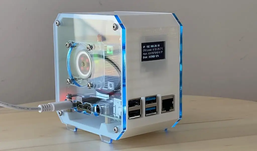
I’ve also made an Ice Edition of this case using white PLA for the case and a blue-tinted acrylic for the side panels. This Ice Edition Kit is available through my Etsy store.
Let me know if you like this Raspberry Pi 4 Desktop Case or what you’d do differently in the comments section.
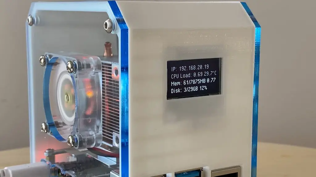
Edit – Alternate Font Option for the OLED Display
Thanks for Richard Jelbert for finding an alternate font which looks much clearer than the default one.
To get this font to work, you’ll need to:
Change the display size setting from 128 x 32 to 128 x 64. To do this you just need to comment out the 128 x 32 line and uncomment the 128 x 64 line a little below it:
# 128x32 display with hardware I2C:
disp = Adafruit_SSD1306.SSD1306_128_32(rst=RST)

# 128x64 display with hardware I2C:
# disp = Adafruit_SSD1306.SSD1306_128_64(rst=RST)
Download the font PixelOperator.ttf from https://www.dafont.com/pixel-operator.font and then place it into the script directory. You’ll then need to edit the below code by commenting out the initial font = Image… line and uncommenting the last line, changing ‘Minecraftia.ttf’ to your font and selecting a suitable font size. Richard has used font size 16.
# Load default font.
font = ImageFont.load_default()

# Alternatively load a TTF font.  Make sure the .ttf font file is in the same directory as the python script!
# Some other nice fonts to try: http://www.dafont.com/bitmap.php
# font = ImageFont.truetype('Minecraftia.ttf', 8)
Re-load the script and you should then get a much clearer text readout on your display.
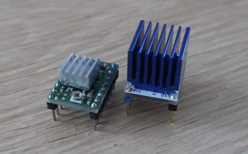
The TMC2208 stepper motor drivers are a popular choice for reducing the stepper motor noise on 3D printers and laser cutters. They’re particularly useful because they can be used as an almost direct replacement for the A4988 stepper motor drivers which are already widely used. They have the same footprint and pin layout so that they are able to operate in place of an A4988 driver without any significant modifications.
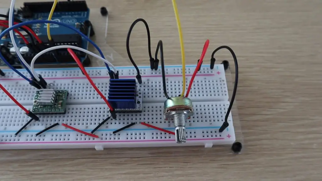
Here’s a photo of the green A4988 driver on the left and the white TMC2208 driver on the right. The TMC2208 driver has a significantly larger heat sink, the boards are actually the same size.
I’ve heard that people have been impressed by how well they’ve worked to silence their 3D printers, but I was curious about how much quieter they would be. So I ordered two to try out. They’re typicallyy about $10 each (including shipping etc.), which is quite a bit more than the A4988’s, which you can often get for $2-3 each, but you only usually need 3 or 4 of them at a time, so it’s not an expensive upgrade. You can also often get much better pricing if you buy an upgrade set of 4 or 5 of them.
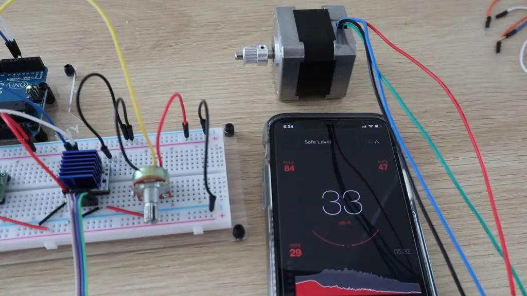
For this test, I’m going to compare the two side by side using the same motor so that you can hear the difference. I’ll also show the actual sound level readout in decibels from an app on my phone for comparison.
Here’s a video of the full test so that you can hear the sound difference for yourself:
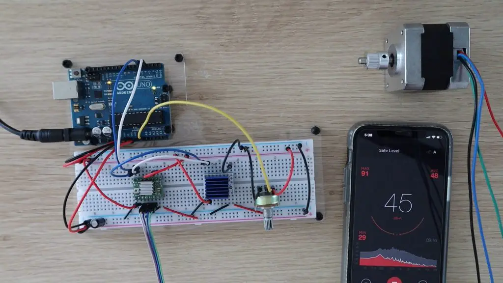
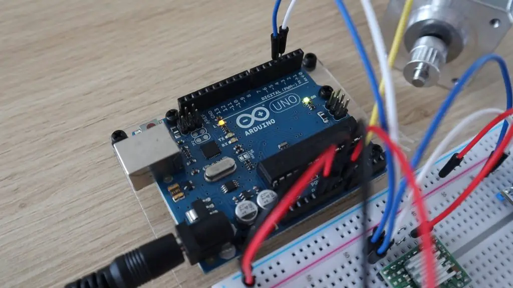
Let’s start by setting them both up on a breadboard so that we can compare them. We’ll use the same signals from the Arduino to each driver, so both drivers are on the same supply voltage, the same logic level voltage and are receiving the same direction and step signals from the Arduino. I’ll just swap the motor connection between the two to change which driver is driving the motor.
I’ve also add a 10K pot to one analog input so that we can adjust the motor speed.
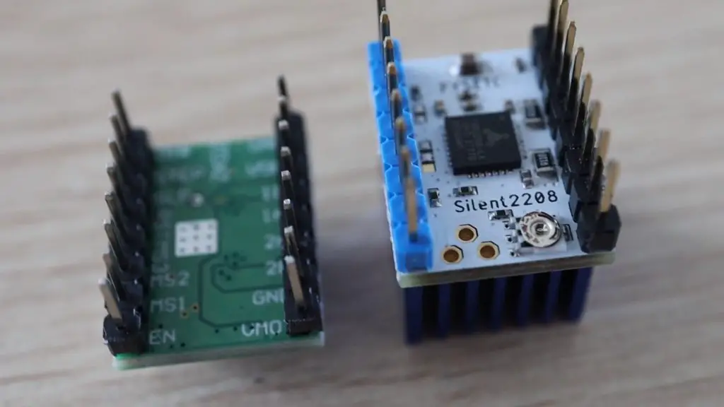
You may also have noticed, with the two boards set up side by side, that the current limit adjustment pot is on opposite sides of the two boards, so keep this in mind if you do swap your A4988 drivers with TMC2208 drivers so that you don’t install them the wrong way around.
Before starting, we’ll also need to set the motor current limit on each driver to suit this motor, which has a rated current of 0.8A. This is important to limit the maximum around of current which can be supplied through the motor coils so that the motor does not burn out.
Here is the sketch that I’m using to drive the motors using the potentiometer:
Lets start by testing the sound level on A4988 driver.
In full-step mode the steps are quite choppy when the motor is turning slowly, if we speed it up a bit it sounds a bit smoother.
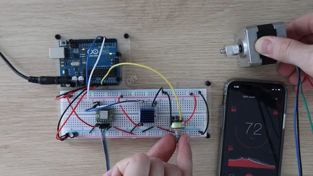
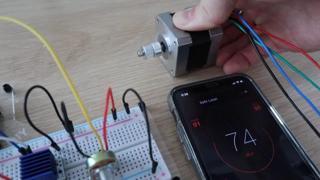
So running at a medium to high speed, we have a sound level of around 74 decibels on the A4988 driver.
Let’s change the motor over to the TMC2208 driver and see how that does. I’ll also be turning the Arduino off between tests so that we’re not swapping the motor over while the coils are being energized.
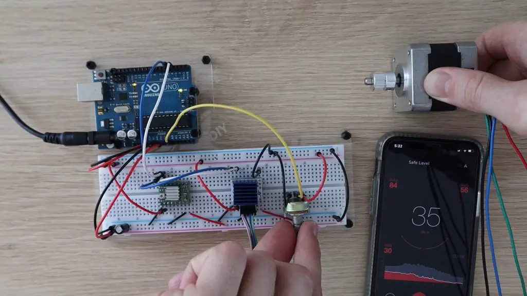
I must admit that when I tried this the first time I got frustrated that I wasn’t getting the TMC2208 driver to work and I kept messing around with the connections and power supply until I noticed that it was actually working, it was just completely silent. I wasn’t expecting such a substantial difference, I thought it would still make a small amount of noise, but it is literally almost completely silent at low speeds.
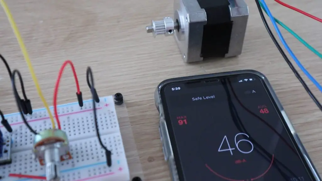
If you turn the speed up a bit you can start to hear it. Even at high speed, we’re only getting an increase of around 3 decibels over the ambient sound level and most of this is caused by the motor “stuttering” which is likely caused by the poor quality connections on the breadboard.
Now, to be fair to the A4988 driver, when operating in legacy mode, the TMC2208 will automatically interpolate the received step signals into 256 micro-steps. So let’s try changing the A4988 driver to 16 micro-step mode (which is the maximum it allows). This allows the driver to micro-step the motor 16 times for each full step, so it should be a bit quieter and smoother. We do this by putting 5V on the three micro-stepping pins on the driver.
Micro-stepping the motor has made it a lot smoother and quieter. We’re now getting a sound level of around 45 decibels, but it’s still way louder than the TMC2208 drivers.
So if you’re looking for a way to make your 3D printer quieter, and it uses these A4988 drivers, then this is a great way to do it without having to spend a fortune.
Let me know in the comments section if you’ve used these drivers on your 3D printer or laser cutter. They’d also be great for camera sliders, where smooth movement is critical.
Owning your first home is an important milestone in life, so it’s important to make it beautiful. Some people prefer to buy their home, while others enjoy starting from scratch and building their own dream house. Both options are fine, but the second one carries more weight as it requires careful planning, analysis, and more effort. Of course, it’s totally up to you to decide which one works better. So, if you’ve decided to design your first family house, here are some important things you should consider.
Be realistic and start slow
Sometimes, it’s easy to get carried away with planning every single detail that you often forget about the basics. But that’s quite common, so before you start planning, remember to keep your head on your shoulders and be realistic about the possibilities. Also, if your architect/interior designer tells you that something is unfeasible, it’s better to listen to them. Doing something just because you want it can have consequences in the future, so make sure to avoid all the risks in the beginning.
Assess your needs first
The number of rooms in your house is important when choosing a layout. So, make sure to assess your needs first? Do you have kids? If yes, then they’ll probably need their own rooms and a bathroom too. Do you or your spouse work from home? Consider getting a home office so you won’t have to work in the dining room. Also, if you have guests frequently then consider adding a separate room where they can sleep in peace. Additionally, you can use one room as your home office and guest bedroom, or even a soothing meditation corner, that way you’ll save space for more important stuff.
If big house is not an option, find other alternatives
A big family house is the ultimate home goal for many, however, in this economy, owning a large property is simply not always an option. Luckily, there are other alternatives that can be equally enticing and elegant, such as modern duplex designs that will accommodate your needs to the fullest. This is great for childfree couples and families alike, but it’s also important to plan the space in communication with professionals, so everything feels fit to a tee.
Include some extra storage space
In many homes, garages are used as storage space, but this doesn’t have to be the case if you plan things well. Of course, feel free to use your garage as you see fit, but when designing your new home, it’s important to include some extra space that can be used for storage. This can come handy if you plan more kids, because keeping strollers, toys and bicycles can become exhausting as time goes by. So it’s always better to have a designated space for things you don’t use on a regular basis.
If you want staircases, plan them properly
Having lavish dramatic or spiral staircases look great in theory, but if you have kids, they can be more of a nuisance than an asset. That’s why it’s crucial to plan the placement of staircases before you have kids or while they’re still too young to walk and explore their surroundings. Unusual or spiral staircases can actually pose a threat for children, as they’re difficult to navigate due to their structure. So before you opt for a staircase, make sure to plan things through and consult an expert who will be able to find the perfect solution for your needs.
Don’t forget your yard space
Yard space can add a whole new dimension to your home, especially if you plan to decorate it with a patio or various plants and even trees. However, before you start planning landscaping, you should make sure to put safety as your top concern, even if you don’t have children. Adding water access such as a swimming pool or a man-made pond can freshen up your backyard, along with a fire pit or an outdoor kitchen. But, in order to make your yard pop, you have to take care of every detail, so hiring a landscape designer or an architect can be a great idea, especially if you don’t have experience in this type of design.
Conclusion
Choosing a family house layout is not an easy task, but with a bit of planning, it’s possible to turn your dreams into beautiful reality for the whole family to enjoy. Just make sure to follow the advice of those who know more, and also, don’t be afraid to voice your concerns or add your opinions, because after all, you and your family will leave there, so be sure to do your best to make your space look great and comfortable.
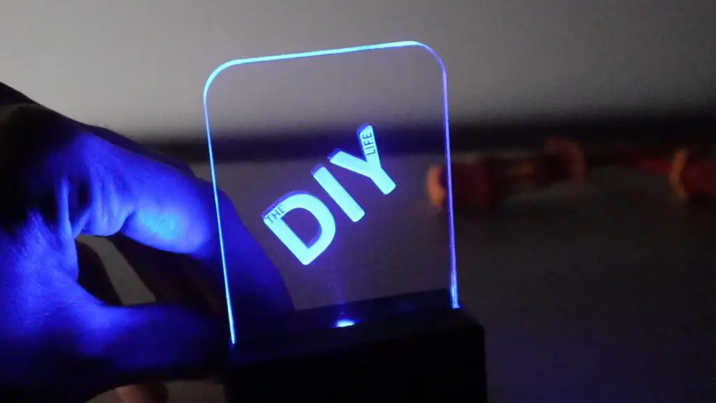
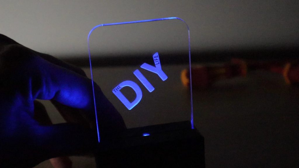
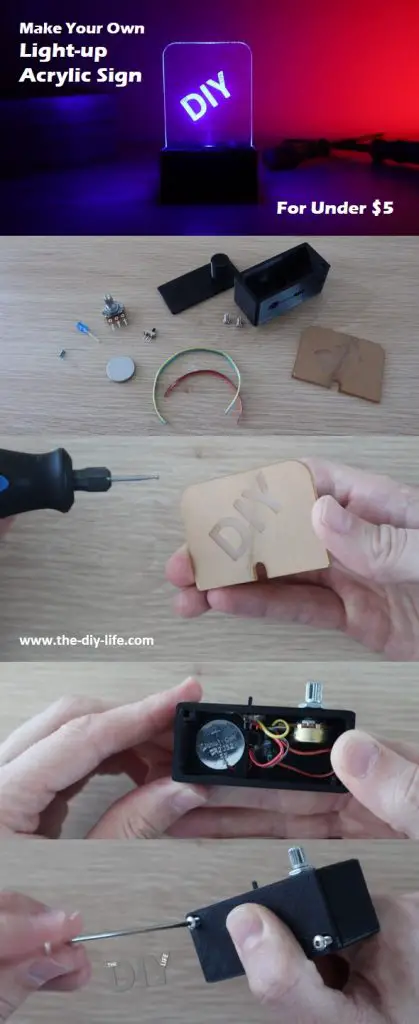
In this project, I’ll be showing you how to make a simple light up acrylic sign with a dimmer and power switch for under $5. In fact, this one cost me just under $3 to make. They’re battery-powered and all of the electronics are contained in the free-standing base, making them perfect for a table, desk, or shelf. The LED lighting is eye-catching, especially in darker environments, so they’re great marketing and promotion tools for indoor or night time events.
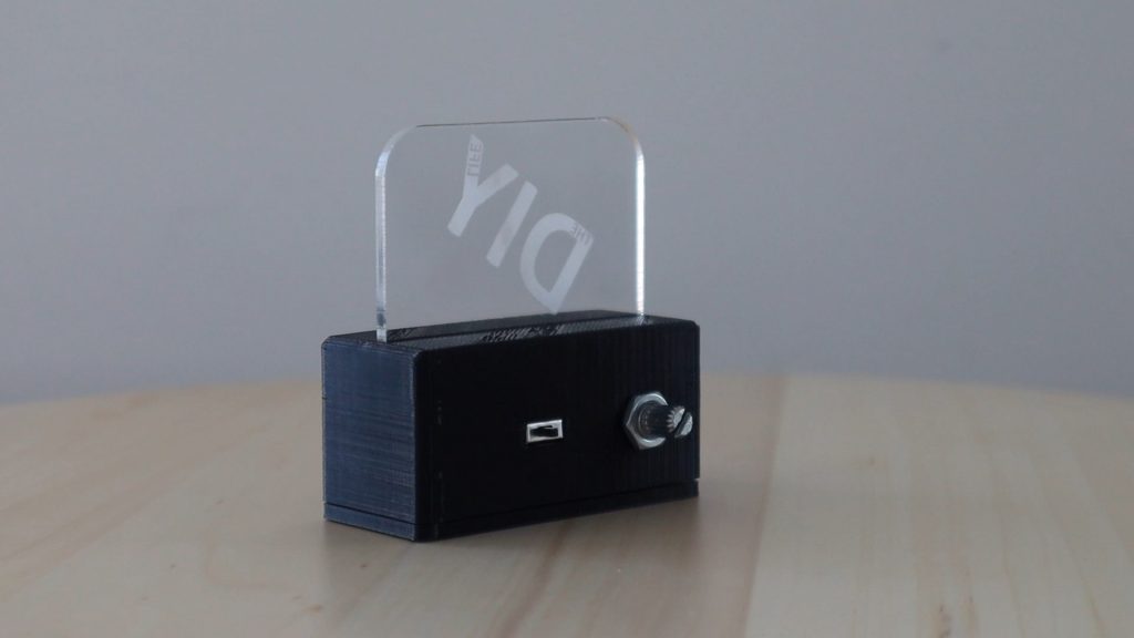
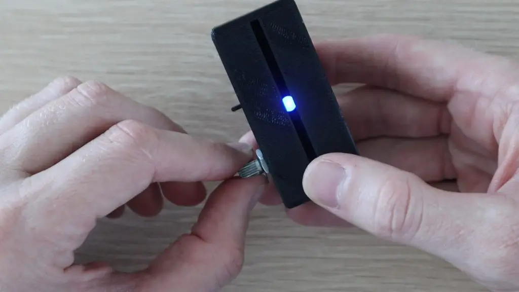
You can change the brightness of the sign using the adjustment pot on the back of the base.
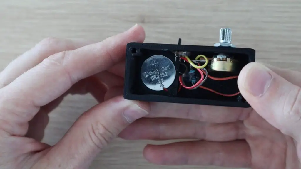
Each sign is powered by a CR2032 coin battery which can easily be replaced through the bottom screw-on cover.
A small power switch and adjustment pot on the back allows you to switch the LED on and off and make adjustments to the brightness.
Here’s a video of the build and the sign being used, read on for the step by step build instructions.
You’re also going to need some basic DIY tools and a 3D printer, but if you don’t have a 3D printer, you can also make use of an online printing service to print the components for you and ship them to your door.
Here’s the 3D printer I’ve used:
Creality Ender 3 Pro – https://amzn.to/3aYDssg
Black PLA Filament – https://amzn.to/2QNYemS
The above links are affiliate links, intended to indicate the correct components required and provide an option for any components you aren’t able to source locally. For this project, it would be most cost effective to visit a local electronic component store to source the parts you need.
How To Make Your Acrylic Sign
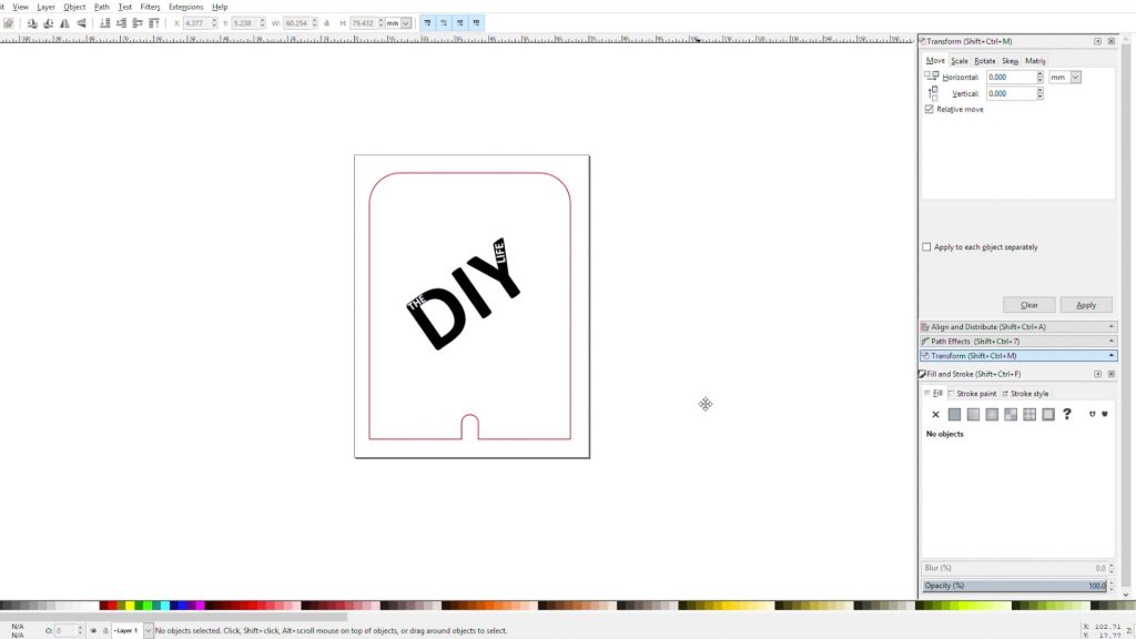
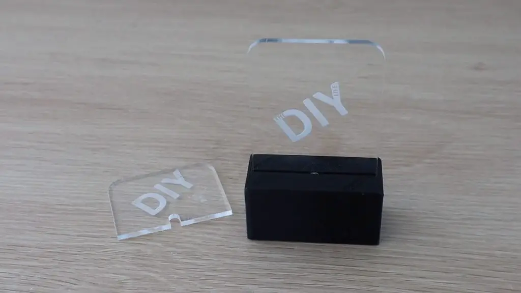
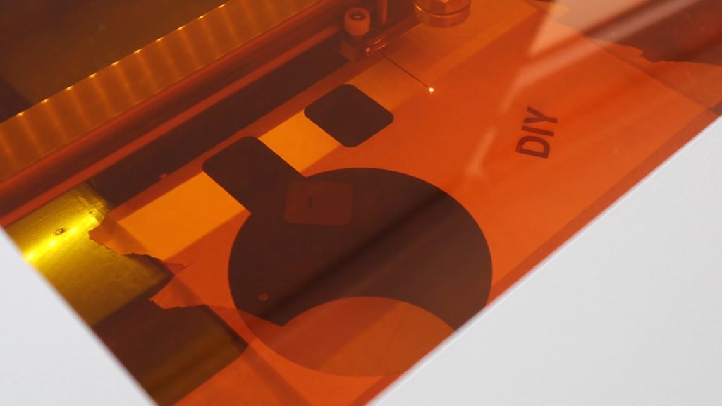
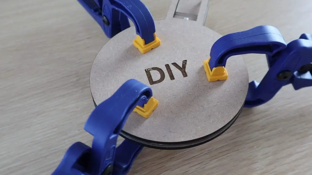
Cut & Engrave The Acrylic
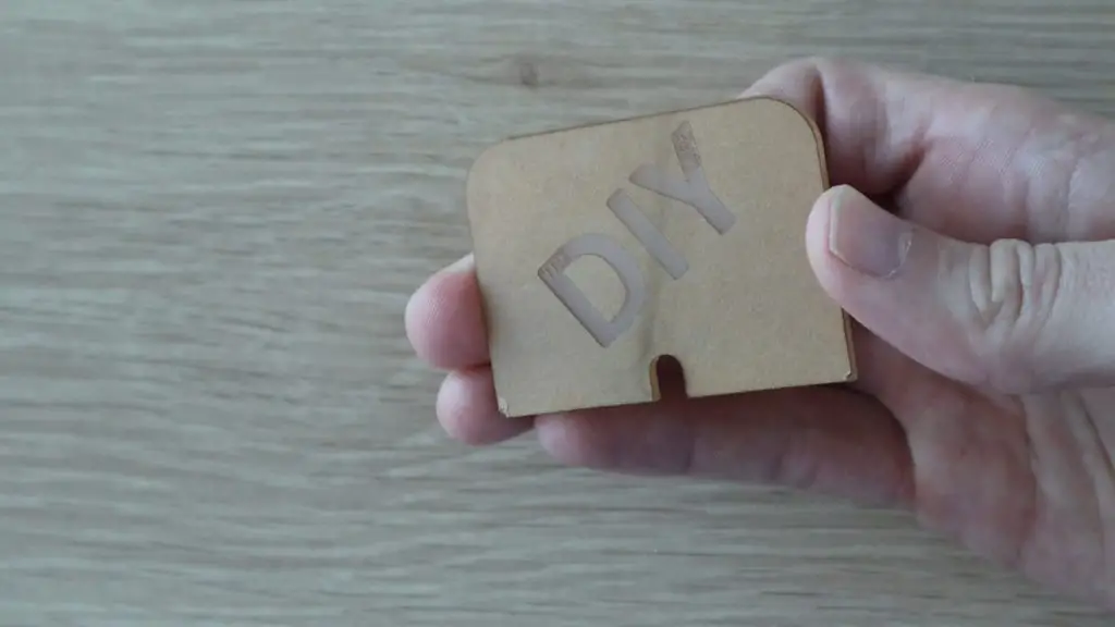
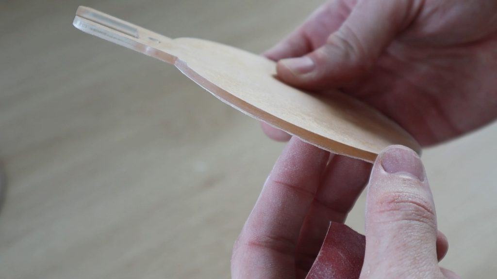
The start out, you’ll need to cut and engrave your acrylic sign. This is the part which is going to be glowing when the LED is illuminated, so it’s worthwhile spending a bit of time on it to make sure that it’s done neatly.
Also, keep the protective film on the acrylic while you’re working on it as any scratches or chips will be illuminated by the LED as well.
I designed the sign to be 60mm wide with a 5mm cutout in the center for the LED. You can make the sign as tall as you’d like to accommodate your logo and any text you want to display. Any length up to 120mm on this size base should work well.
You can print out the templates provided through the above link as a guide, or use the .svg files to laser cut your own. I’ve used two sizes in this example, a smaller one which is 50mm high and a larger one which is 80mm high.
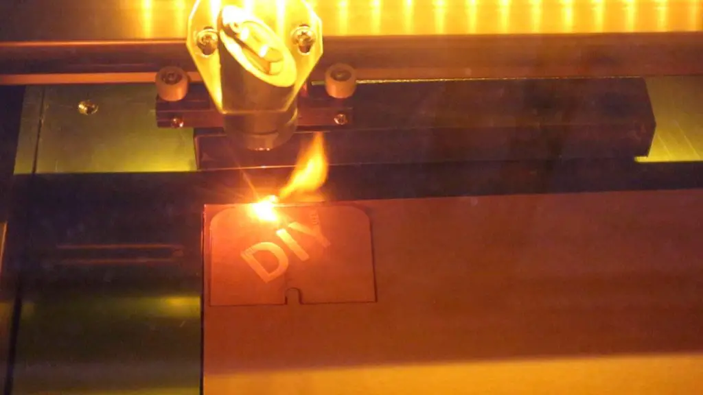
The easiest way to cut and engrave the acrylic is with a laser cutter. If you don’t have access to one, there are a number of online services that will cut and engrave the acrylic for you.
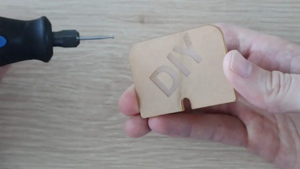
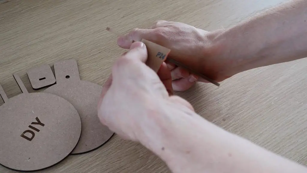
If you’d like to keep the cost down, you can also cut the acrylic yourself using a simple hack saw or band saw and engrave your logo by tracing out the text using a sharpie and then engraving it with a Dremel or other rotary type tool.
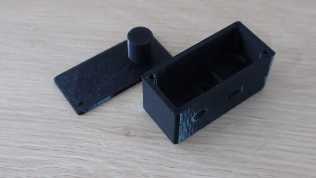
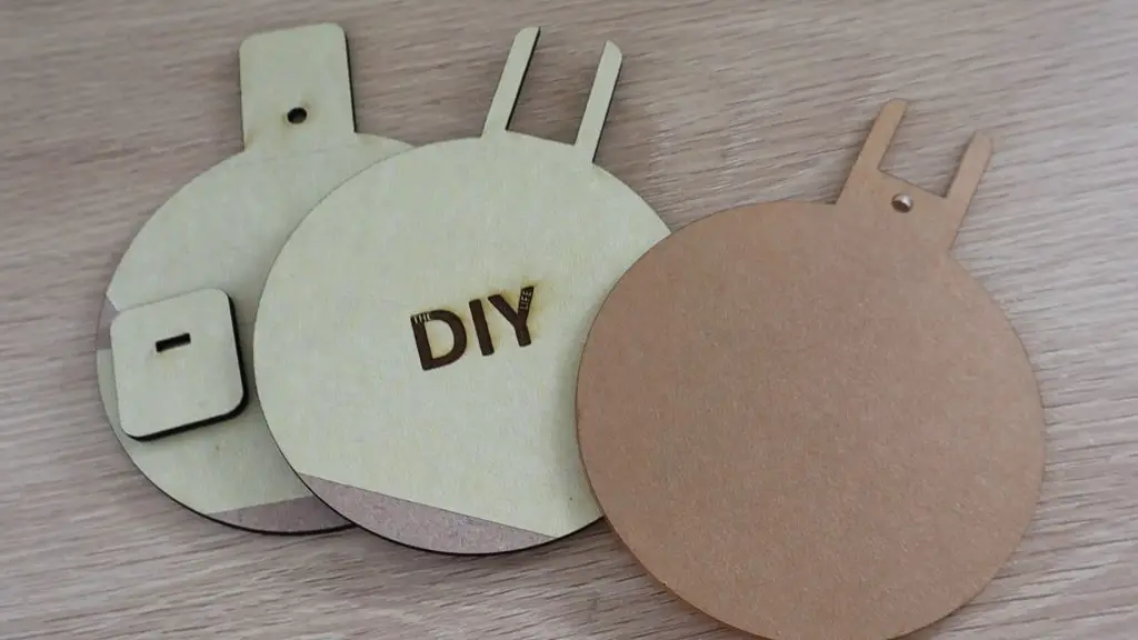
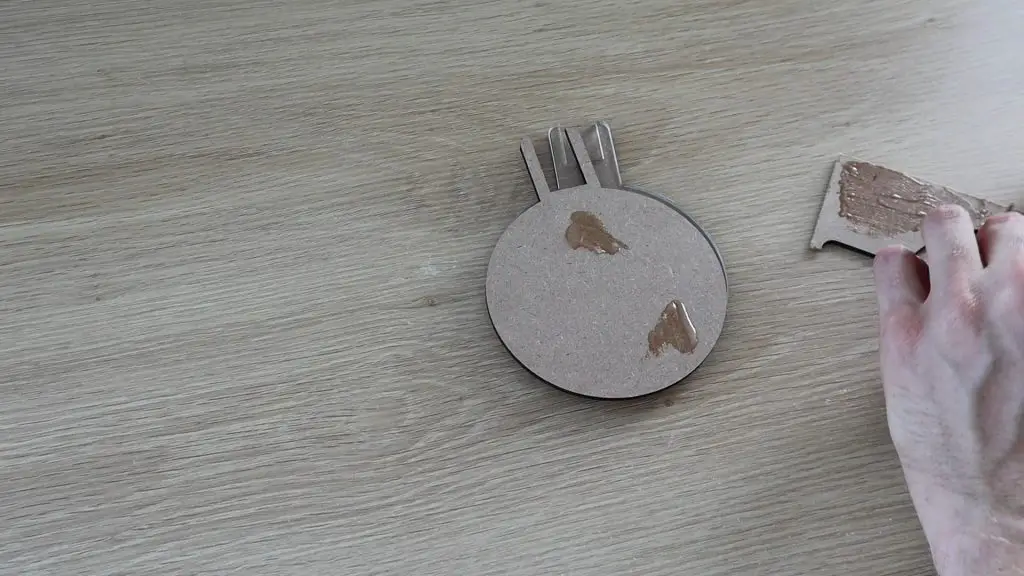
3D Print The Base
Next, you’ll need to print out the two plastic components which make up the base. I printed these out in black PLA with a 15% infill.
You can make the base any colour you’d like to match your theme or brand colours.
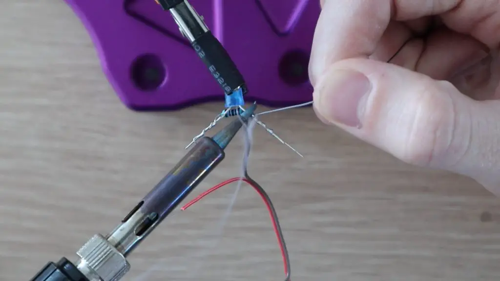
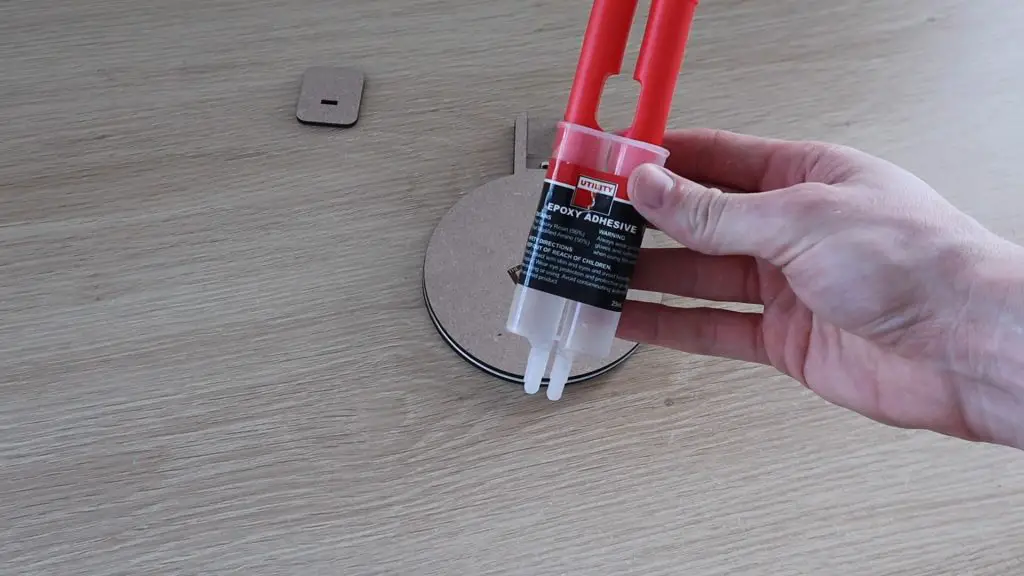
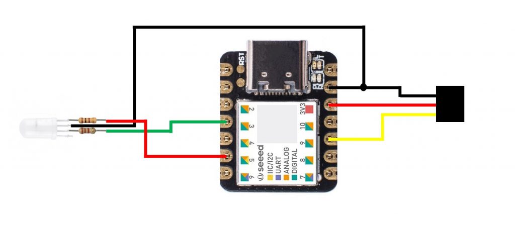
Solder The Electronic Components
Finally, we’ll assemble the electronic components.
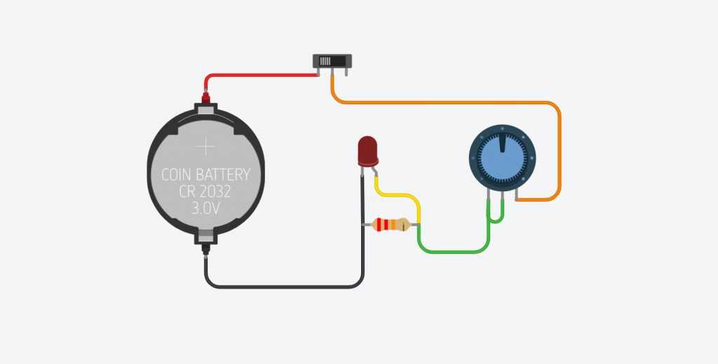
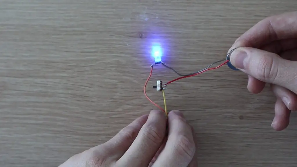
The circuit is a simple LED dimmer circuit with a 22K resistor across the LED and a 10K pot to control the brightness. It’s connected to a power switch to turn the LED on and off and the lead then feeds into the battery tray in the housing, so you don’t need to buy a separate battery holder.
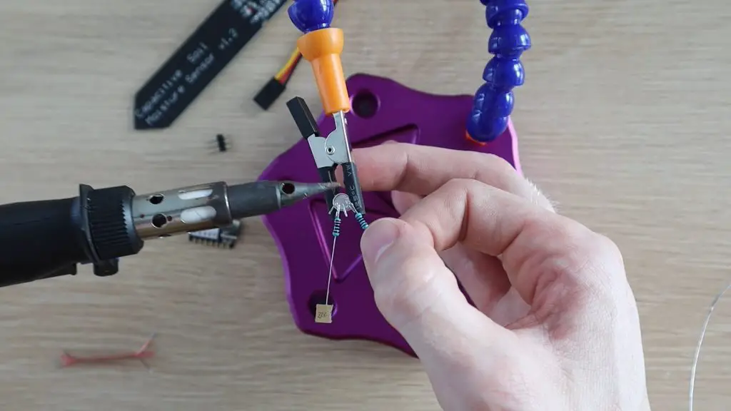
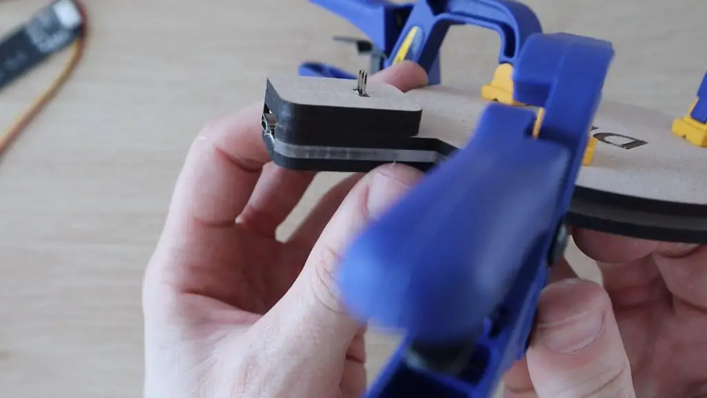
Try to solder the resistor directly across the legs of the LED and the bridge onto the legs of the pot to save additional wiring.
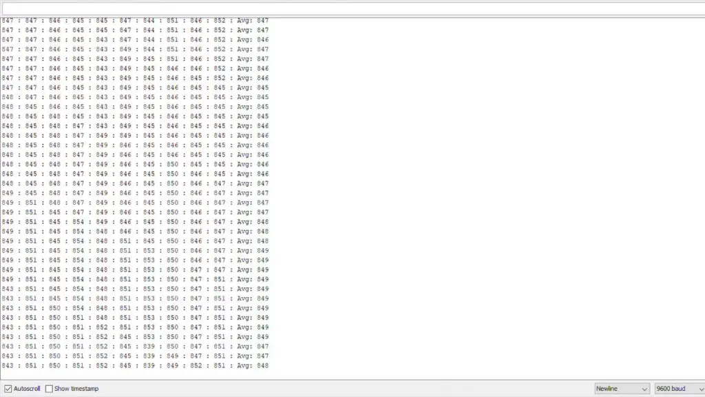
Try holding the leads onto the battery and sliding the power switch to provide power to the LED and test that the circuit works. Also, try turning the pot and check that the LED is able to be dimmed.
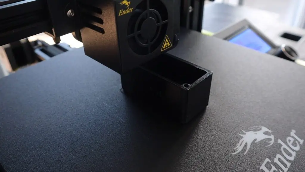
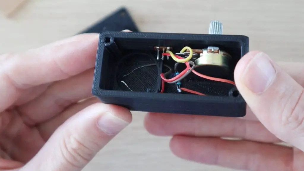
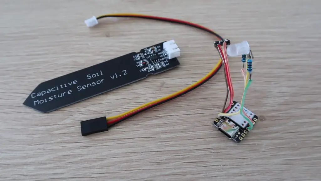
Once you’ve soldered and tested the electronics, install the components into the housing.
There are already cut-outs in place in the housing for the switch and the pot.
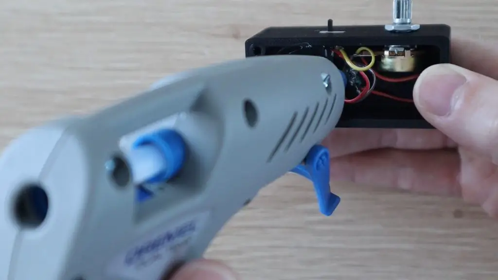
I put a drop of hot melt glue onto the inside of the switch and over the LED to keep them in place.
The pot is held in place with a nut on the outside.
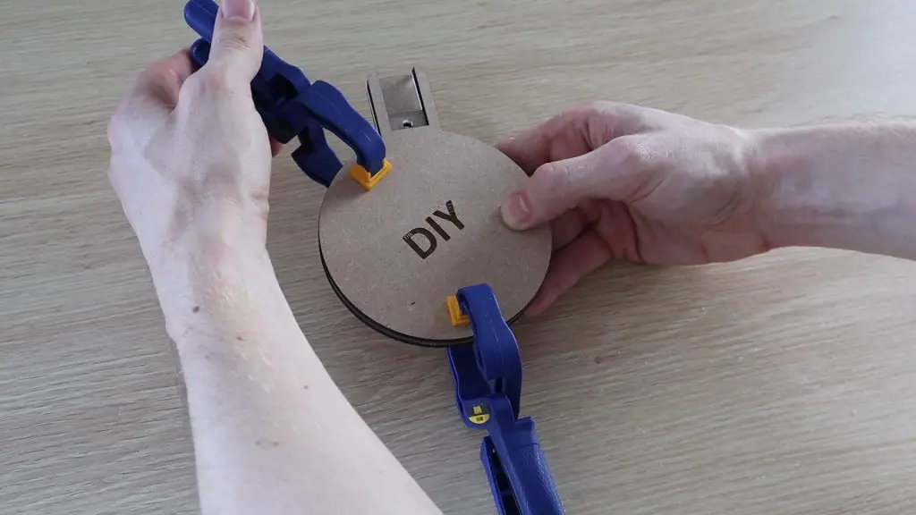
Assemble The Acrylic Sign
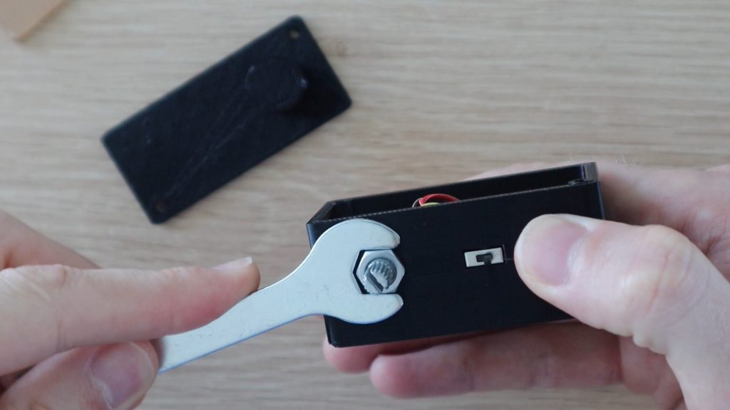
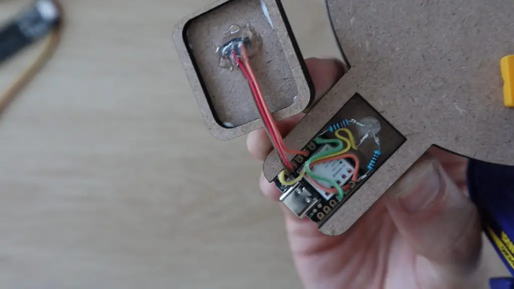
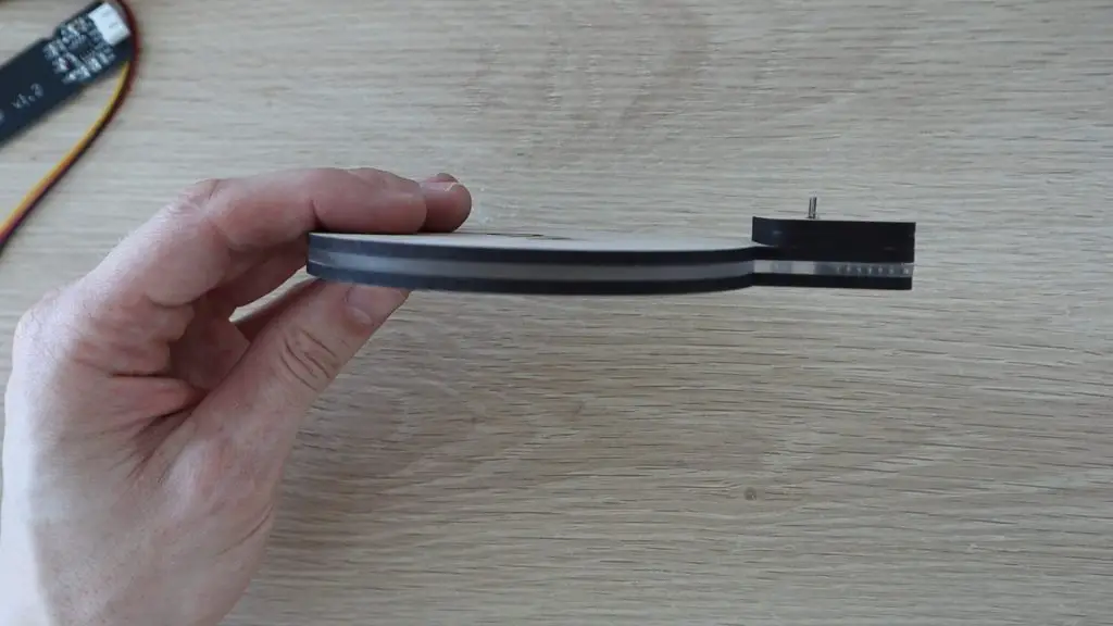
To complete the sign, you need to install the battery, close up the base with the cover and then insert the acrylic sign.
Place the battery into the battery holder with the negative lead touching the bottom of the battery. Then place the positive lead over the top of the battery.
When you install the bottom cover, the cylinder on the cover will press this lead down onto the battery to keep it in contact.
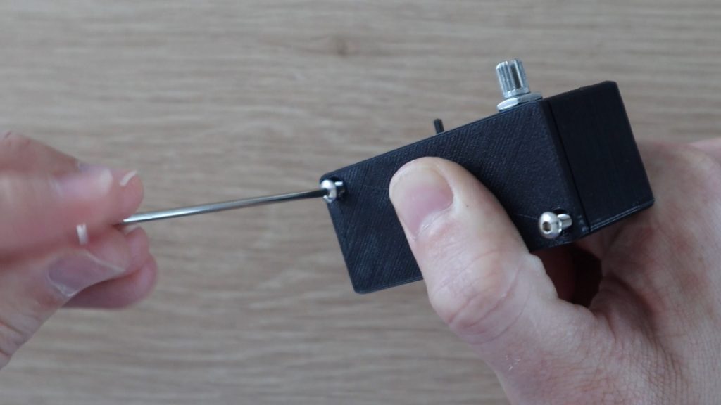
Once you’re happy with everything functioning then close up the bottom cover and secure it with two M3 x 15mm machine screws.
You can do one last check on the electronics before installing the acrylic sign if you’d like.
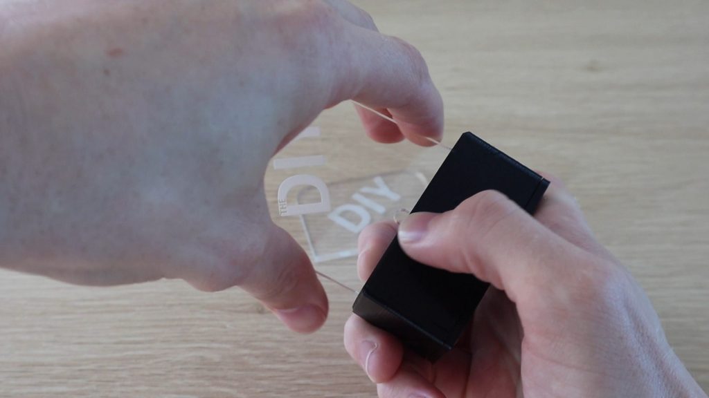
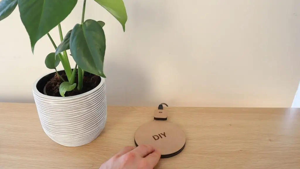
Now you just need to push your acrylic sign into the base and switch it on. It should be a snug fit into the base so you don’t need to glue it and you can then easily swap out or change the signs if you’d like.
You sign is now complete.
I hope that you enjoyed this project, have fun making your own Acrylic signs. Let me know what you’ve made them for in the comments section.
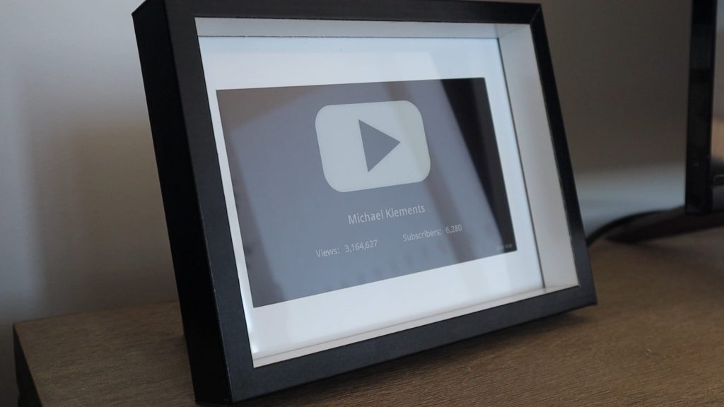
I’ve seen a couple of different designs for YouTube subscriber counters and social media follower counters and I had a Raspberry Pi Zero W lying around which I wanted to put to use. I didn’t want the distraction of a bright LCD display at night, so an e-ink or e-paper display seemed like the best option. So, in this project, I’ll show you how to make your own Youtube Subscriber Counter using a 7.5” Waveshare E-Ink display and a Raspberry Pi Zero W to update it.
The Raspberry Pi uses a Python script to query the YouTube API a couple of times a day and then refreshes the e-ink display to update the counter. It’s really simple to make as it just uses the Waveshare Hat for Raspberry Pis, so there is no soldering required and you don’t have to worry about tinkering with any other electronics to get it working.
The e-ink display provides great visibility during the day, even in bright light, and only uses power when it’s being refreshed, so the counter uses very little power to run. The updates take about 40 seconds to complete and between updates the Pi uses around 0.5W while at idle.
Here’s a video of the build and the display updating, read on for the step by step instructions to build your own.
What You Need To Make Your Own Youtube Subscriber Counter
Waveshare 7.5” HD E-Ink Display (B) With Controller – Buy Here
6×8” Shadow Box Frame – Buy Here (The one linked to is not exactly the same as used in the project, but the most similar I could find on Amazon)
Keyboard, Mouse & Monitor For Setup (Or Connect Through SSH)
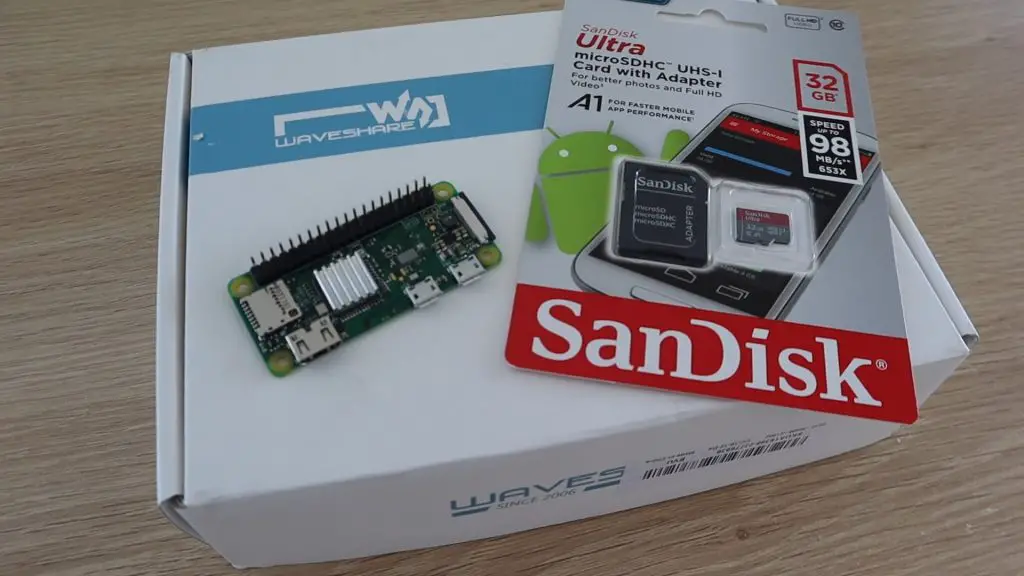
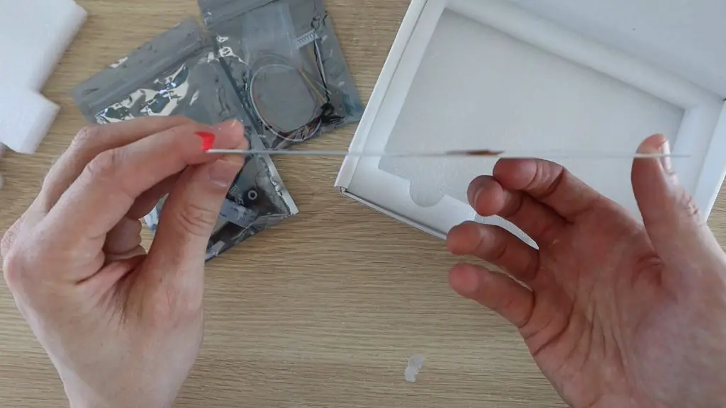
All you need for this project is a Raspberry Pi Zero W, an SD card, and a Waveshare E-Ink Display, make sure that you order the display which includes the hat display controller for the Raspberry Pi. You’ll also need a suitable frame to put it in, you may even have one lying around your home.
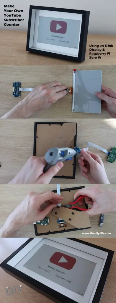
Connect & Prepare The Electronics For Your YouTube Subscriber Counter
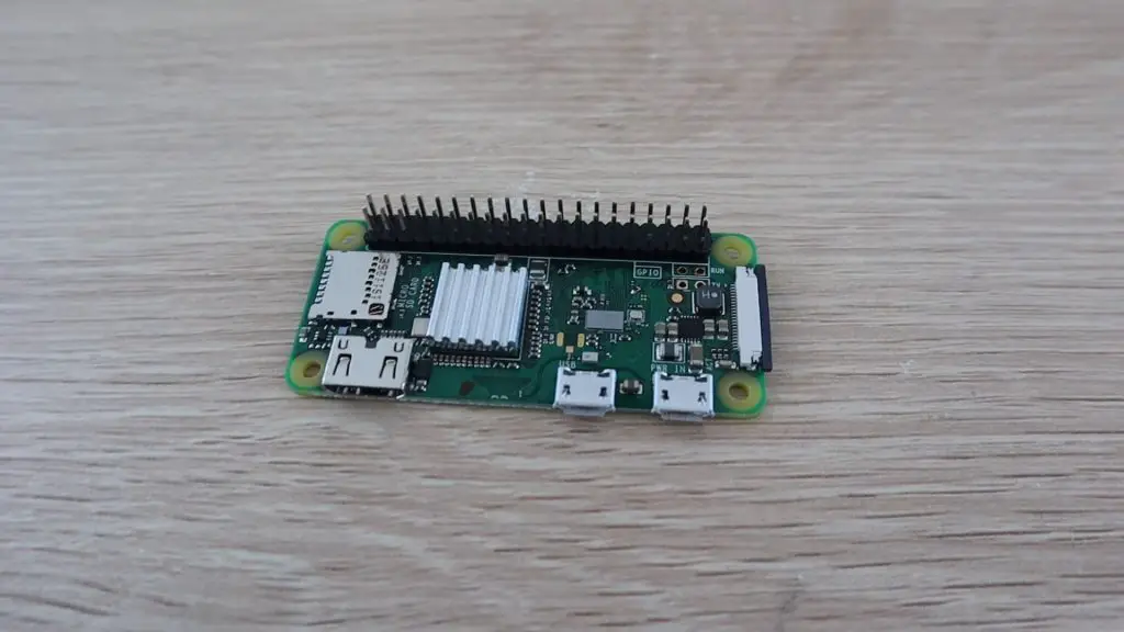
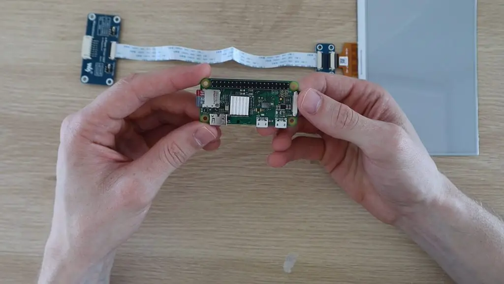
Let’s start by preparing the Raspberry Pi Zero W. You’ll need the header pins to be soldered to your Pi Zero, so if yours didn’t come with them already installed, then you’ll need to install them before starting. Also, attach the heat sink to the CPU, this project isn’t particularly strenuous on the CPU, but it’s a good idea to install it anyway.
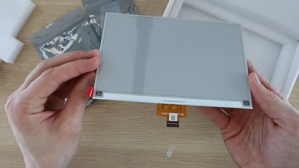
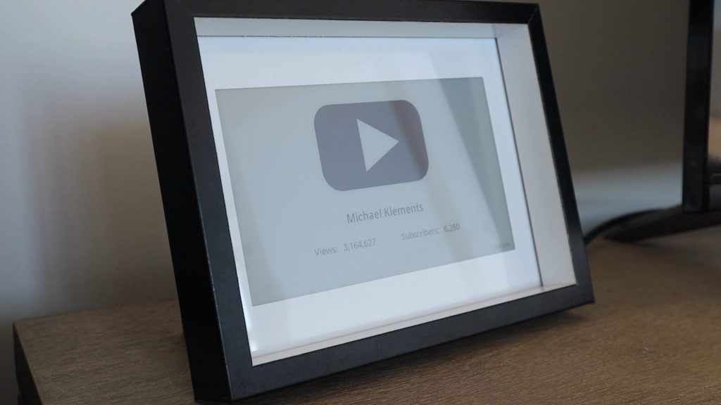
Once your Pi is prepared, you can connect the display. I’ve used the 7.5” HD 3 colour version, the three colours being white, black and red. You also get a two colour version which is just black and white and another 3 colour version which had yellow instead of red. The red just works better for the YouTube play button.
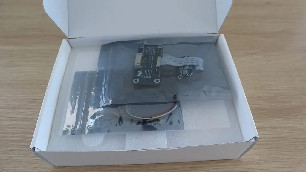
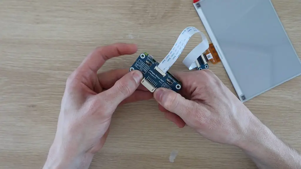
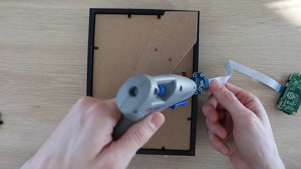
In the box, you get the SPI e-paper display controller, which is designed as a Raspberry Pi hat, to plug directly onto the GPIO pins. It also includes a plug and a set of leads to connect the controller to another SPI capable device, such as an Arduino or ESP32.
The actual display is really thin and has a thin ribbon cable at the bottom which plugs into the controller.
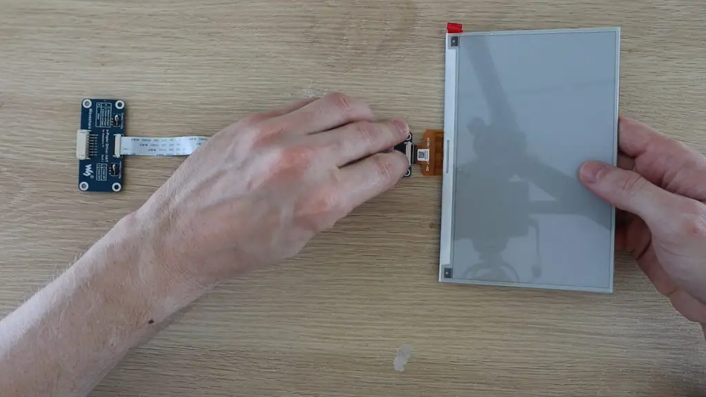
To connect the electronics together, you simply lift the black tab on the back of the connector, plug the display’s ribbon cable into the connector and then push the black tab down to lock it into place. Make sure that you get the orientation of the plug correct, the components are all face-up when laid on a flat surface.
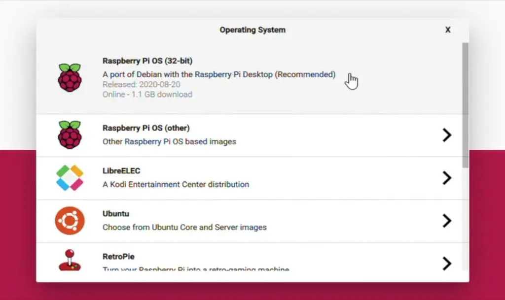
You’ll need to prepare your SD card with an installation of Raspberry Pi OS, which can now be easily done using the Raspberry Pi utility for Windows and Mac computers. You just choose the operating system you’d like, then the target SD card, and the utility does the rest for you.
For this project, you can use the full version of Raspberry Pi OS or the Lite version which doesn’t have the GUI (graphical user interface) if you’re comfortable using the terminal (command line prompts) to set it up. If you’re planning on setting it up using SSH then you’re better off just using the Lite version.
Plug your formatted SD card into your Pi and then plug the hat onto the GPIO pins.
You can now get started testing the display. I’d suggest that you get it working like this before building it into the frame if this is your first project using one of these e-ink displays.
The Waveshare Wiki for the 7.5″HD e-Paper Hat (B) is a great place to start. It walks you through the exact steps required to get the example code working and the display running through some example images and text. The Python script used for this project is based on this Waveshare example script.
If you’re not comfortable tinkering with the display and working through this Wiki then just follow the steps I’ve outlined in the subsequent sections to get it working for this specific project.
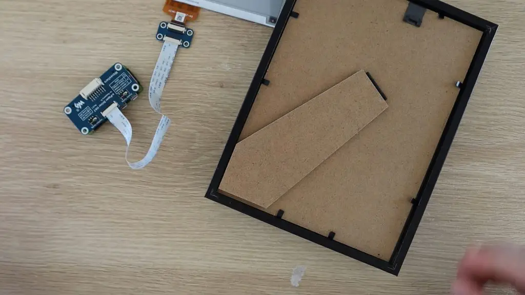
Build The Electronics Into The Frame Or Display Box
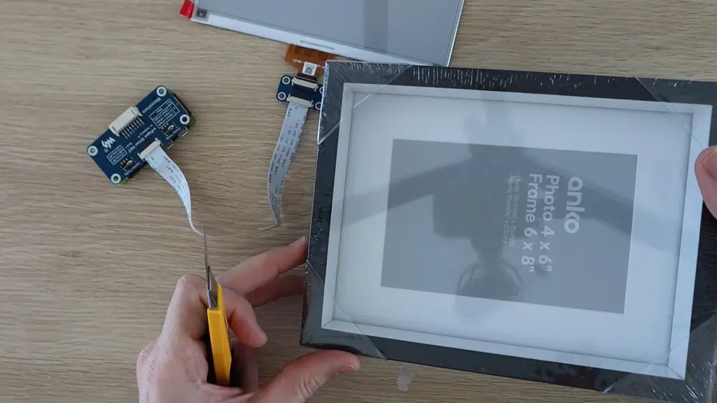
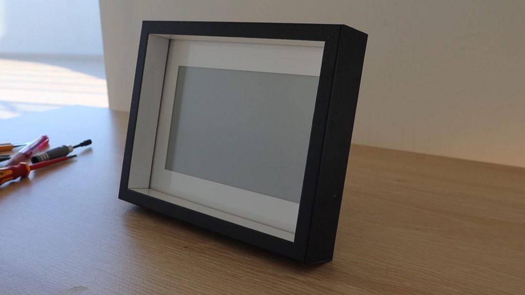
Now let’s build the display into the frame or display box. I found this cheap 6×8 inch box frame which will work quite well. You should be able to pick up a shadow box or deep photo frame around this size from a local discount store for a few dollars.
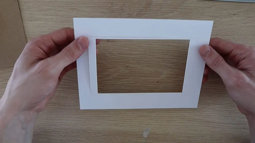
I started by removing the back layer to get to the white frame panel.
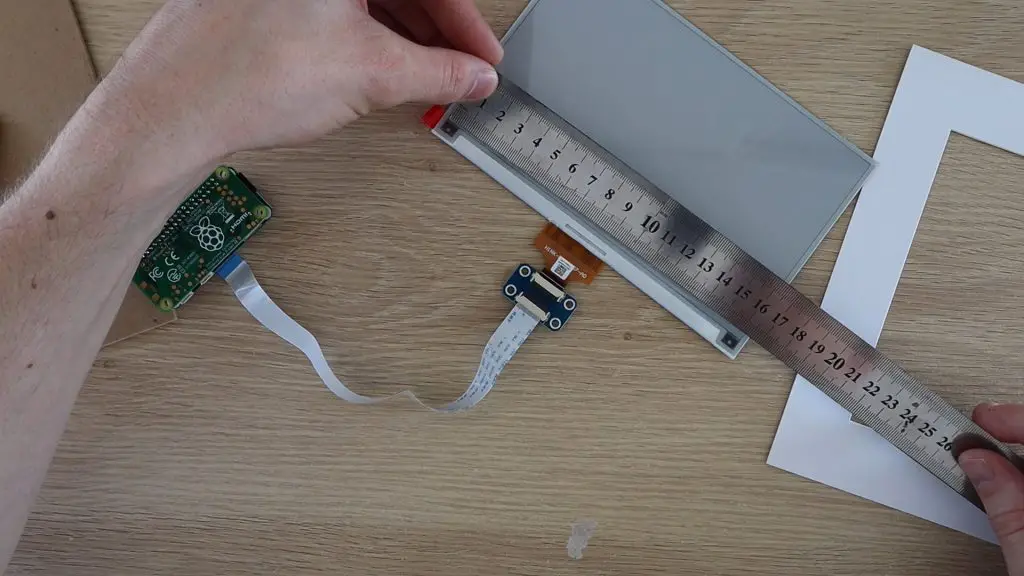
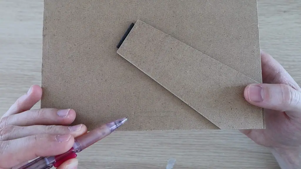
This is likely sized for a 4×6 inch photo like mine, so you’ll need to open it up a bit using a craft knife and a ruler so that it fits your display.
Measure the size of the display area and then mark it out on your frame insert.
Use a sharp craft knife and a ruler to cut along the new lines to open the frame up to fit the display.
You could also just adjust the display content size to fit within the frame area if you don’t want to modify yours.
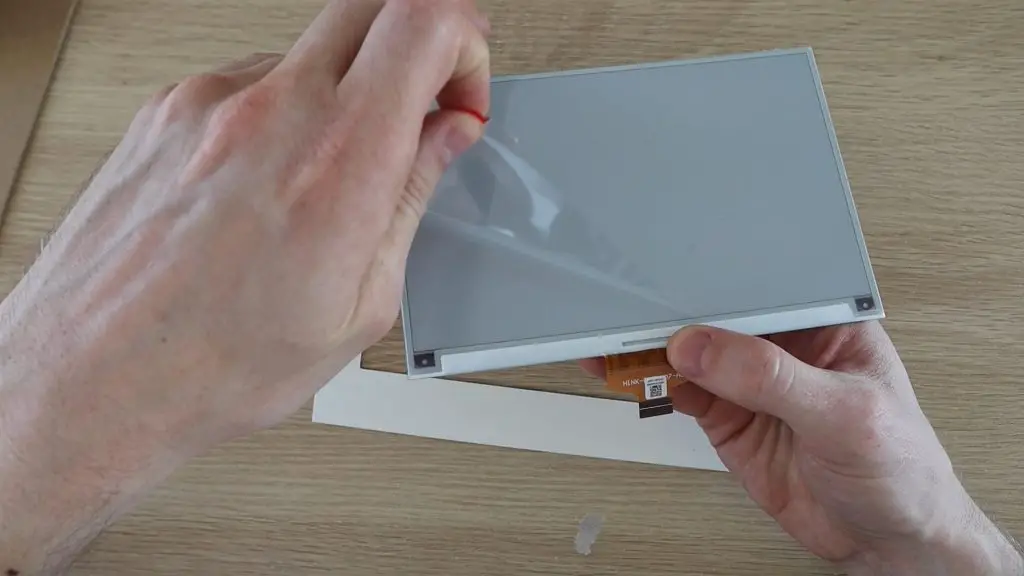
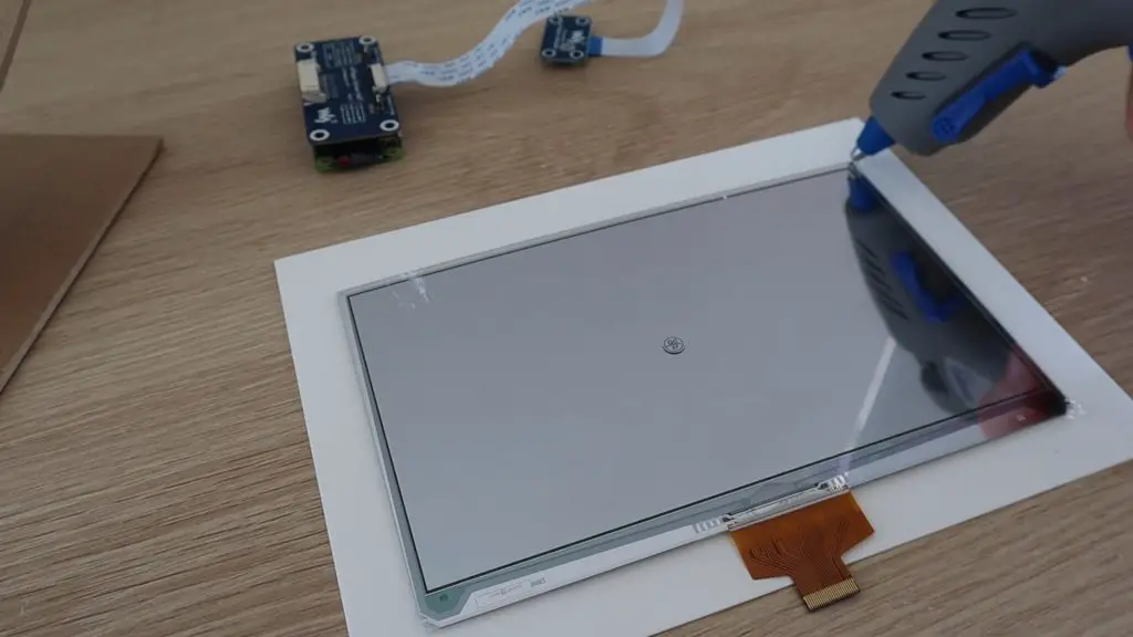
Peel off the protective film from the display.
Then carefully glue the back of the display to the frame, making sure that it’s centred and straight. I used a drop of hot glue on the corners to hold it in place.
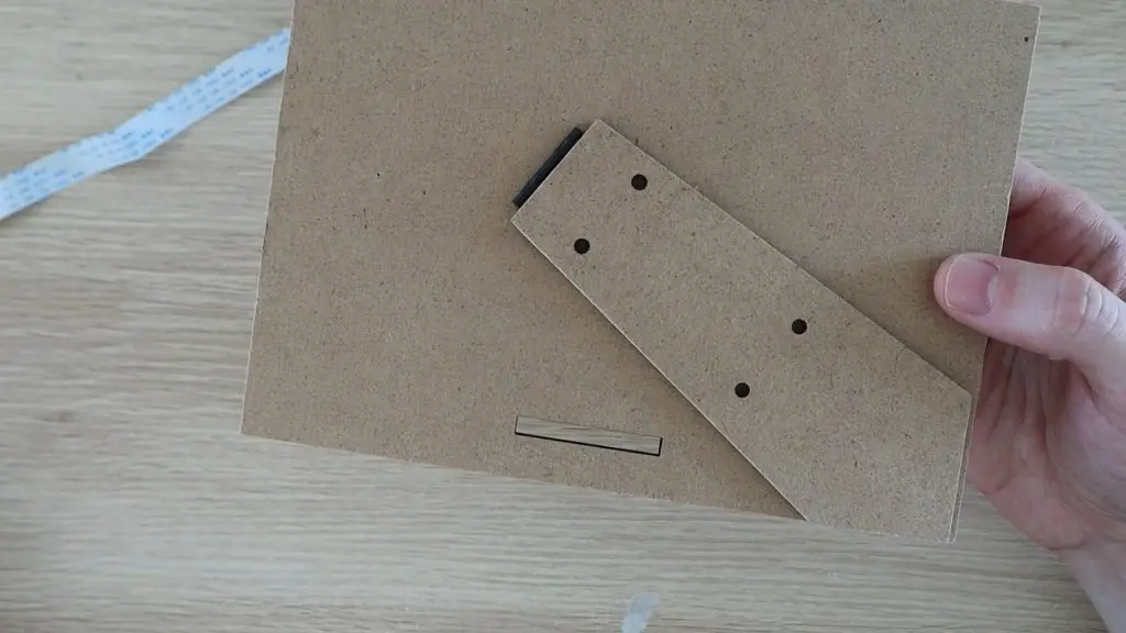
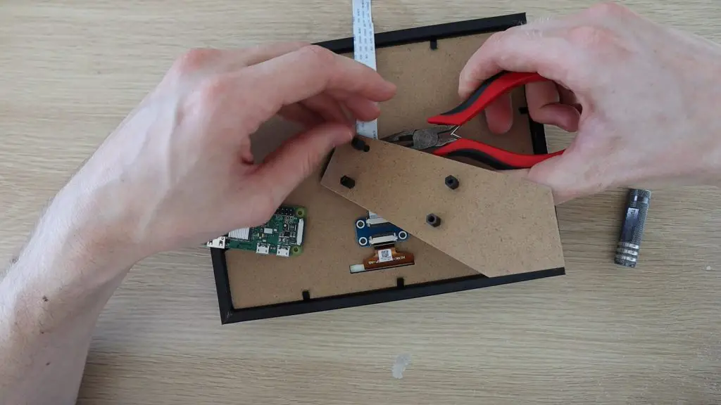
Next, mark out and cut a slot in the back layer to pull the display’s ribbon cable through.
I also made the holes to mount the Raspberry Pi onto the stand.
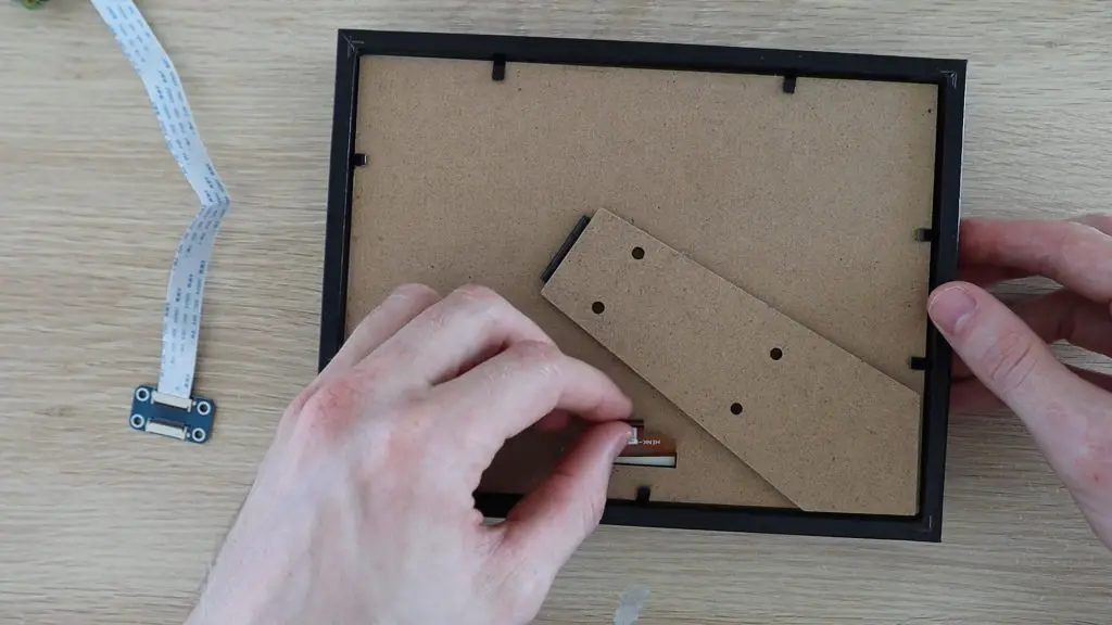
Now re-assemble the frame and clamp the back layer back into place. If you don’t want a glossy finish to your frame, you could remove the glass panel from the front or use a matt finish panel instead.
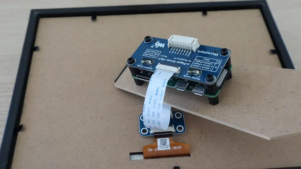
Plug the display back into the controller and glue the connector in place so that it doesn’t put any stress onto the display’s ribbon cable.
Now lets add some plastic standoff mounts to mount the Raspberry Pi and the Hat.
Your frame is now complete and ready for programming.
Setting Up & Programming Your Raspberry Pi Zero W
The first time you boot up the pi, it will take a while to set up the Operating System, get connected to your WiFi network, and do any updates. Most of this is done automatically and you should be guided through prompts until you get to your Desktop view and your Pi is ready for programming.
Before you start with the Python script, there are a couple of libraries to install and setup steps to work through.
Please also remember that software changes quite often with these devices, these steps work as of 6 October 2020, but you may encounter errors in the future as packages are updated and pieces of software become obsolete.
The Raspberry Pi communicates to the display controller using the SPI interface, so you’ll need to enable it on your Pi.
Open the terminal window and enter the following command:
sudo raspi-config
Choose Interfacing Options -> SPI -> Yes
You may need to reboot your Pi for the changes to take effect.
sudo reboot
Once you’ve restarted your Pi, open a new terminal window again and enter the following to install the libraries:
Install the BCM2835 libraries:
wget http://www.airspayce.com/mikem/bcm2835/bcm2835-1.60.tar.gz
tar zxvf bcm2835-1.60.tar.gz
cd bcm2835-1.60/
sudo ./configure
sudo make
sudo make check
sudo make install
In order for the Python script to retrieve your current subscriber count and number of views, you’ll need to add your Channel ID and your YouTube API key.
Go to your Dashboard and the click on “Create Project”, choose a name for your project and click “Create”.
Next, click on “Enable APIs and Services” and type – Youtube Data API v3 – into the search box. Enable it and click “Create Credentials”.
On the next page, you should see a link to create an API key in small letters, click on this link.
Next click “API Restrictions” and select “YouTube Data API v3”.
Click “Create” and you should then be given your API key which you’ll need to copy into the main Python script below.
You’ll also need to get your Channel ID. You can find this under “Advanced Settings” for your channel account. Click on your profile picture in the top right, then go to “Settings”, wait for the page to load and then click on “Advanced Settings” from the menu on the left.
You can test your API Key and Channel ID by going to the following address in your broswer, replacing YourChannelID and YourAPIKey with the ones you’ve just got:
We start by importing the libraries, functions and directories needed as well as getting the current date.
We then use the Youtube API to get the subscriber count and number of views. Remember to update these in your script before running it, just replace the ****** with your own ID and Key.
We then format the returned numbers with commas and finally connect to the display to update it. You’ll also need to update your channel name to your own channel name by replacing the “Michael Klements” with your own channel name in this portion of the code.
The script then puts the display into a low power sleep again until the next update.
If you’d like to play around with the layout of the display, try adjusting the numbers in the display portion.
draw_blackImage.text((200, 435), noViews, font = font24, fill = 0)
The first number is the X position and the second number is the Y position of each object to be displayed.
You’ll also need to run the setup.py script, included with the above code download, once before you run the actual script:
Try to run the script and after a few seconds, you should see your display start to refresh. The full refresh of the display does take quite a while, somewhere around 30 seconds on the Raspberry Pi Zero. It is a bit faster on a Raspberry Pi 4.
The flickering is normal for these controllers and is done to prevent burn-in on the display. It’ll first flicker black and white to clear the display, then load a black and white version of the image and finally replace some of the black with red as instructed.
Schedule The Python Script To Run Automatically
Once you’ve got the script working, you’ll just need to schedule the script to run automatically using crontab, mine updates the YouTube subscriber counter display every 8 hours, running three times a day. You could probably just refresh the display once a day, but Waveshare recommends updating the display at least once every 24 hours to prevent burn-in. So I just went with every 8 hours to be safe.
I followed this guide by scottkildall to get crontab to automatically run the script at 6AM, 2PM and 10PM.
You essentially need to create a launcher.sh script in the same folder as your Python script:
#!/bin/sh
# launcher.sh
# navigate to home, then script directory, then execute, then back home

cd /
cd home/pi/SubCount/SubCount/
sudo python3 subCount.py
cd /
This script tells the Raspberry Pi to change directory to the home directory, then navigate to your script, then run the script using python3 and then go back to the home directory.
Once you’ve got your launcher script created, open crontab by opening a terminal window and entering:
crontab -e
You’ll then edit crontab to run the launcher.sh script by adding lines:
Save the changes and your Raspberry Pi should now be all set to update automatically at 06:00, 14:00 and 22:00. You can edit the minutes and hours in the above lines to set the times you’d prefer. The first is the minutes and the second the hours, in 24 hour format.
Using Your YouTube Subscriber Counter
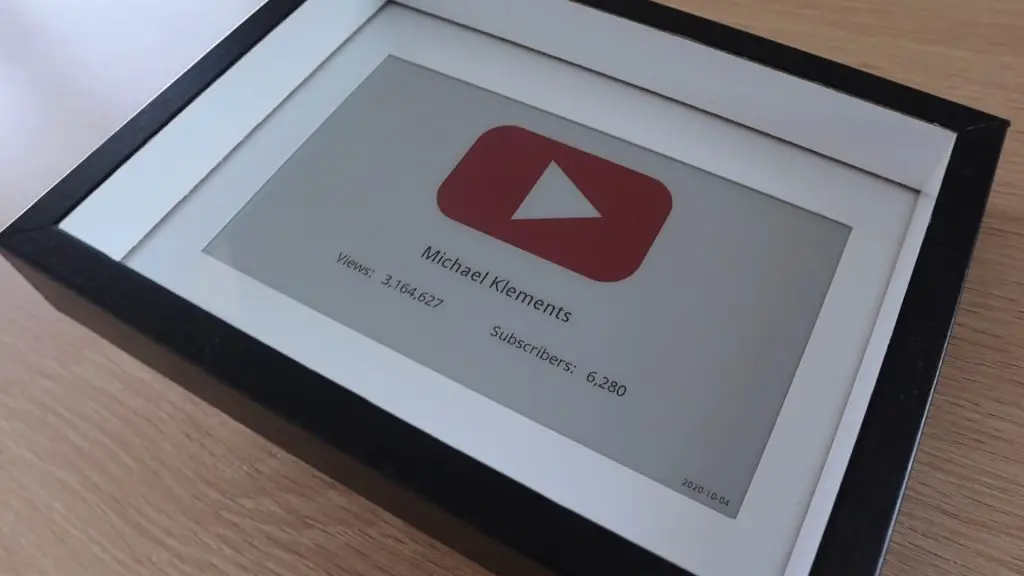
Once you’ve got the scripts set up and scheduled to run automatically, your Youtube Subscriber Counter is complete. Just plug it into a USB power supply and place it on your desk or shelf.
The date in the bottom right corner is updated to reflect the last time the stats were updated, so you’ll be able to see if anything goes wrong and the Pi stops updating the display regularly by checking this date as well.
I wanted to build this particular YouTube Subscriber Counter using a Raspberry Pi Zero W, but you could also use an ESP32 to use even less power by putting the controller to sleep between updates to the display, something that’s difficult to do on a Raspberry Pi.
Let me know what you think of it in the comments section and let me know if you try building your own!
A while ago, I made a soil moisture monitoring stick that gives you some useful information about the soil moisture level for your indoor plants.
It does a great job, providing indication LEDs and giving you a numerical readout of the moisture content of the soil, but it looks quite ugly stuck into your pots and it’s not easy to see the flashing LEDs from far away. This got me thinking of a way to make a better-looking moisture level indicator which could give you all of the basic information you need at a glance, a smart indoor plant base.
After throwing around a couple of ideas, I thought of making a round base for the pot to stand on, similar to a coaster, with an indicator layer which could be lit up in different colours to indicate whether your plant needs some attention.
The indicator layer would be lit up in green when the plant had enough water and red when it needed more water. I could also create a colour fade between these two limits as a sort of level indicator. So a greeny-yellow would mean that there’s still a fair amount of water, while an orangy-yellow would mean that you’d need to water the plant soon.
I didn’t want the base to become bulky and unattractive as well, so I wanted to keep it as thin as possible.
Here’s a video of the build and the smart indoor plant base in use, read on for the full step by step instructions.
I decided to use a layer of 3mm acrylic wedged between two layers of 3mm MDF. An RGB LED on the back would illuminate the edges of the acrylic to be green when the plant was healthy and red when it needed some attention, with the levels in between being varying shades of yellow.
I’ll still be using the same soil moisture sensor that I used previously, only now it won’t have any other electronics attached to it, all of the processing will be done in the base by the small microcontroller.
The microcontroller I decided to use was this Seeeduino XIAO. It’s really small, has an ARM Cortex CPU, and is Arduino compatible, so it’s easy to program and interface with the components. The best part is that they cost just $5 from Seeed Studio.
Designing The Smart Indoor Plant Base
I started out by measuring the base of the pot so that I could design the new base to be slightly larger. I designed the three circular layers of the base and the small enclosure at the back to house the Arduino.
The Arduino has a built-in USB C port for power, so it’s easy to just plug the base into a USB outlet using a USB C cable to power it once it’s built.
The components were designed in Inkscape so that they can be exported for laser cutting.
Once the components were designed, I cut them out on my laser cutter.
If you don’t have a laser cutter, you can also easily cut MDF and acrylic with a hand saw. Just print out the PDF template supplied with the laser cutting files and trace them out onto your MDF and acrylic.
In order for the edges of the acrylic to light up evenly, you need to roughen them with some sandpaper so that they’re opaque. The rough edges diffuse the light and make the acrylic layer look as if it is lit up entirely.
I used some 240 grit sandpaper until they had an even white appearance all around.
Next, I glued the three layers together using some epoxy adhesive.
Use a small amount of epoxy, you don’t want it to seep out of the edges and onto the areas you’ve just sanded or you’ll need to sand them again.
I used some small tool clamps to hold the layers in place while it cured.
Solder The Electronic Components Together
While the epoxy was curing, solder the electronic components together.
The circuit is not very complex as you’ve only got two components to interface with the Arduino, the sensor and the LED:
You need a current limiting resistor on each leg of the LED, 100Ω on the red leg and 220Ω on the green leg, and some header pins to plug the moisture sensor into. The green light from the LED tends to be more intense and washes out the other colours, so I used a higher resistance on the green leg than the red leg to balance it out.
I connected my soil moisture sensor the 3.3V output on the Arduino. I have noticed that some of these sensors don’t run reliably (or some even at all) on 3.3V, although they are supposed to be able to accept 3.3V to 5V. If yours is not working correctly, try powering it from the 5V supply on the Arduino – VCC. The sensor steps the voltage down in any case, so you’ll still only be supplying 3.3V back to the analogue input. Be careful if you’re using a different sensor as this Arduino’s analogue inputs can only accept a maximum of 3.3V.
Install The Electronics Into The Base
Next, you’ll need to install your soldered electronics into the housing at the back of the base.
When I tried to assemble my electronic components I saw that I had been a bit optimistic in thinking I’d get all of the components into the two-layer space. So I cut an additional spacer to create a bit more headroom. This spacer is included in the cutting file download and should be glued to the underside of the top cover.
Push your LED into the hole in the acrylic, not too far as you want the brightest part to be in the acrylic layer. Then glue your Arduino into the housing and glue the pins into the cover layer. It’s a good idea to cover up the soldered joints on the header pins so that they don’t short out on the LED legs when you assemble it.
Lastly, close the housing up. I used a glue gun as it’s quicker to work with, but you can use your epoxy adhesive as well.
That’s it for the assembly, now we just need to program and calibrate it.
Programming The Arduino
The sketch is quite simple, it just takes analogue readings from the moisture sensor and then adjusts the LEDs proportionally between two limits.
You’ll need to calibrate and set the two limits up according to your own plant as some plants need more water and some can survive in dryer soil. Essentially you want the LED to be red when you need to water it and go green once you’ve given it enough water, you shouldn’t need to over-water the plant to get the base to turn green. There’s more about this setup step later on.
In my first revision of the sketch I just updated the LEDs with the value read from the sensor. I noticed that there was some variation between measurements and every so often there was a value significantly higher or lower which caused weird colour flicker to occur.
So I switched to a moving average system where the average of the past ten readings is taken and this produces much more consistent results and a slow fade when you water the plant. This is why the code looks a bit more complex than it should have been.
Here is the final version of the sketch:
//The DIY Life
//Michael Klements
//26 September 2020

#define greenLED 3                                        //Define the IO pin numbers
#define redLED 5
#define moisturePin 9

#define wetCal 750                                        //Wet and dry calibration limits
#define dryCal 1023

int measurements [10];                                    //Array to store the last 10 measurements
int counter = 0;                                          //Counter to keep track of the current array position

void setup()
{
  pinMode(greenLED, OUTPUT);                              //Define the pin modes
  pinMode(redLED, OUTPUT);
  for (int i=0; i<=9 ; i++)                               //Populate the array with starting readings from the sensor
    measurements [i] = analogRead(moisturePin);
}

void loop()
{
  addData(analogRead(moisturePin));                                       //Take a new reading and add it to the array
  int moistureLevel = getAverage();                                       //Get the new average of array readings
  if(moistureLevel > dryCal)                                              //Constrain reading between the high and low limits
    moistureLevel = dryCal;
  else if(moistureLevel < wetCal)
    moistureLevel = wetCal;
  int greenBrightness = map(moistureLevel, dryCal, wetCal, 0, 255);       //Calculate the green and red LED brightness according to the reading
  int redBrightness = map(moistureLevel, wetCal, dryCal, 0, 255);
  analogWrite(greenLED, greenBrightness);                                 //Set the green and red LED brightness
  analogWrite(redLED, redBrightness);
  delay(2000);
}

void addData(int num)                                                     //Function to add a reading to the array and increment the counter
{
  measurements [counter] = num;
  if (counter < 9)
    counter++;
  else
    counter = 0;
}

int getAverage()                                                          //Function to return the average of all readings in the array
{
  int ave = 0;
  for(int i=0; i<=9 ; i++)
    ave = ave + measurements [i];
  ave = ave/10;
  return ave;
}
We start by defining the IO pin numbers and the calibration limits, we then have an array to store the last ten readings and a counter to keep track of the array position being updated.
In the setup function, we define the pin modes and then populate the array with ten initial readings from the sensor as a starting point.
In the loop function, we take a new reading and call the addData function to add the reading to the array in the current position. We then get a new average value for the array before checking that the value is within the wet and dry limits. If it is not, it is limited to a maximum and minimum, being the two limits.
We then map the average moisture level to a corresponding green and red led brightness and then set the LED brightness accordingly using a PWM output. We then wait 2 seconds before repeating the loop.
We then have two functions, addData and getAverage which manage the data in the array. The addData function just adds the latest measurement to the array at the current position and then increments the counter. The getAverage function returns the average of all of the values in the array.
Calibrate the Sensor
As mentioned previously, you’ll need to calibrate your sensor in order to get meaningful results from the base. The best thing to do is to start when your plant soil is “dry” or at a level where you’d expect to need to water your plant again.
Place your plant onto the base, push the sensor into the soil, and plug it into the header pin socket.
Connect the Arduino to your computer using a USB C cable, and open up your Serial monitor on your Arduino IDE. Output the soil moisture readings to the monitor, one every second or two, and note the average of around 10-20 readings once they’ve stabilised (aren’t varying significantly). This will be your dry setpoint.
Once you’re happy with your dry readings, you’ll need to water the plant. Water your plant as you would normally, giving it enough to be fully absorbed into the soil, but not over watered. Now do the same as you did before and take the average of around 10-20 readings on your serial monitor. This will be your wet setpoint.
Update the two setpoints in your code and then re-upload the sketch to start using the base properly.
Since you’ve just watered your plant to calibrate it, the indicator layer should now be green. It will slowly go red again over the next few days as the soil dries out.
Using The Smart Indoor Plant Base
You’ve now got a smart base for your indoor plants which shows you at a glance when your plant needs to be watered.
The Smart Indoor Plant Base when your plant needs more water:
Give your plant some water:
After a minute or so, the water should be absorbed into the soil and the sensor base should indicate that the plant has been watered:
The base after a day or two when the water is drying up:
If you’re going to use yours in a really sunny room then you’ll probably want to add two or three LEDs and possibly another layer of acrylic to brighten the display a bit. Else you’ll only be reminded to water your plant at night.
Let me know what you think of this smart indoor plant base in the comments section. Are you going to try building one?