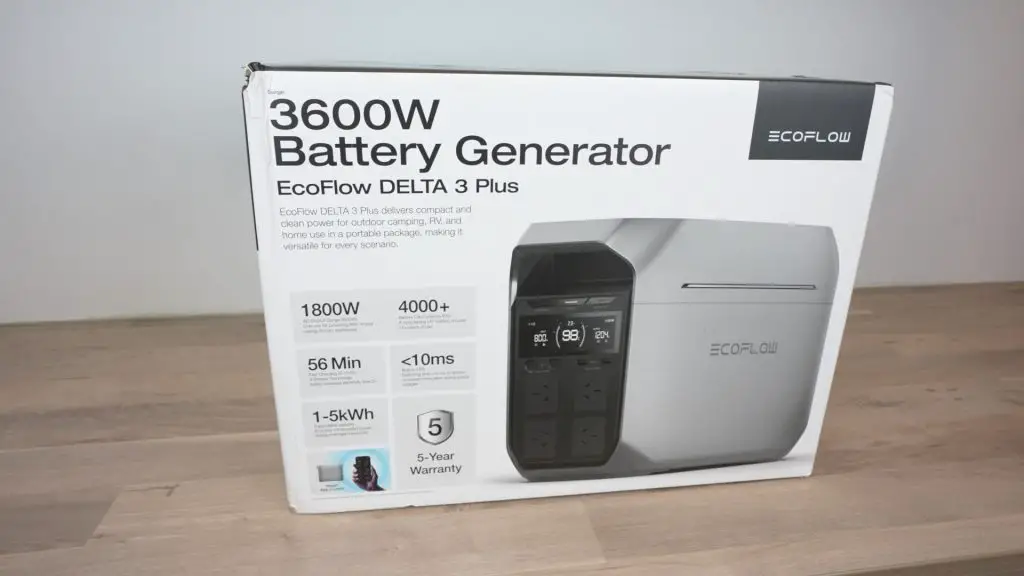
Today we’re going to be taking a look at the EcoFlow Delta 3 Plus portable power station. This is the latest iteration of their Delta series, including a 1024Wh battery and 1800W pure sine wave inverter alongside a host of other exciting features.
If you don’t know what a portable power station is, it is an all-in-one battery, charger, inverter and DC power supply in a compact and portable package. They’re great for taking care of your power needs on days out, at work sites, in the event of a power outage or on camping trips.
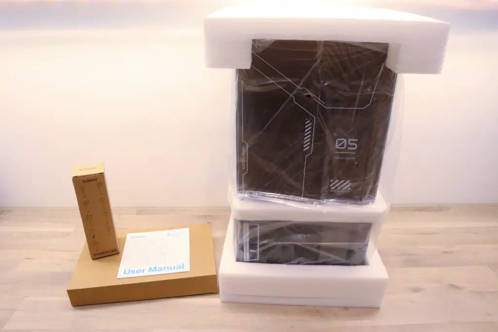
EcoFlow have sent me the Delta 3 Plus to try out, so let’s get it unboxed and then we’ll take a look at what it has to offer.
Here’s my video review of the Delta 3 Plus, read on for the written review;
Where To Buy The EcoFlow Delta 3 Plus
- EcoFlow Delta 3 Plus (Amazon US) – Buy Here
- EcoFlow Delta 3 Plus (Amazon UK) – Buy Here
- EcoFlow Delta 3 Plus (Web Store) – Buy Here
Equipment Used For Testing
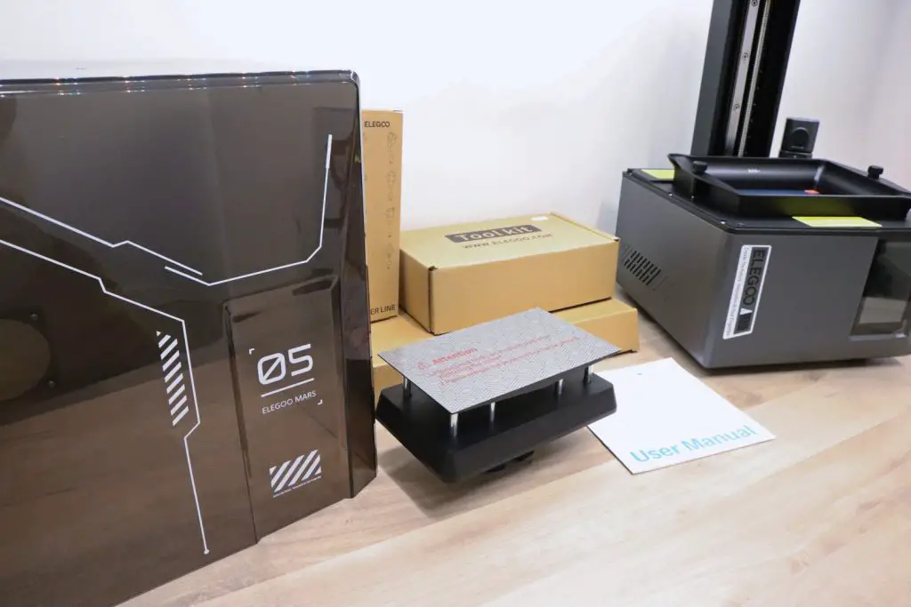
Unboxing And First Look At The Delta 3 Plus
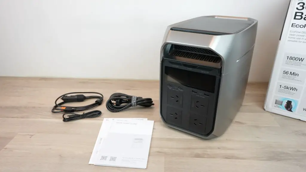
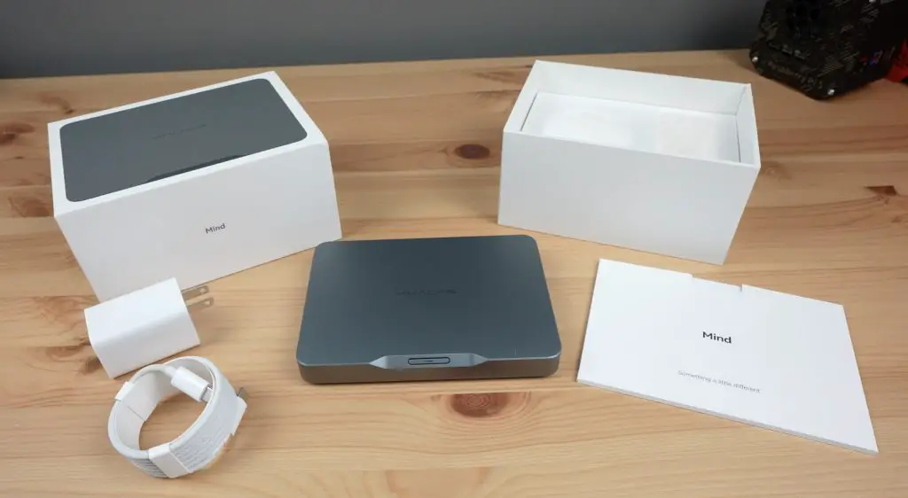
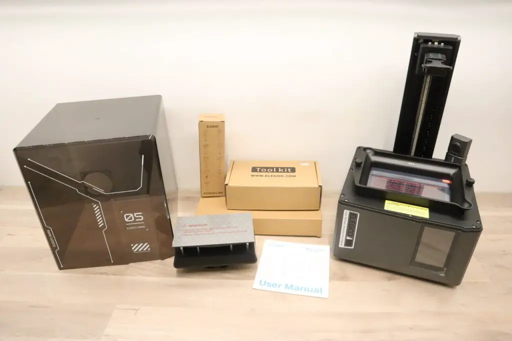
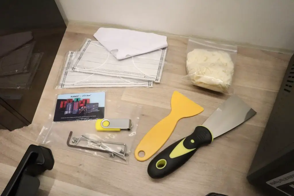
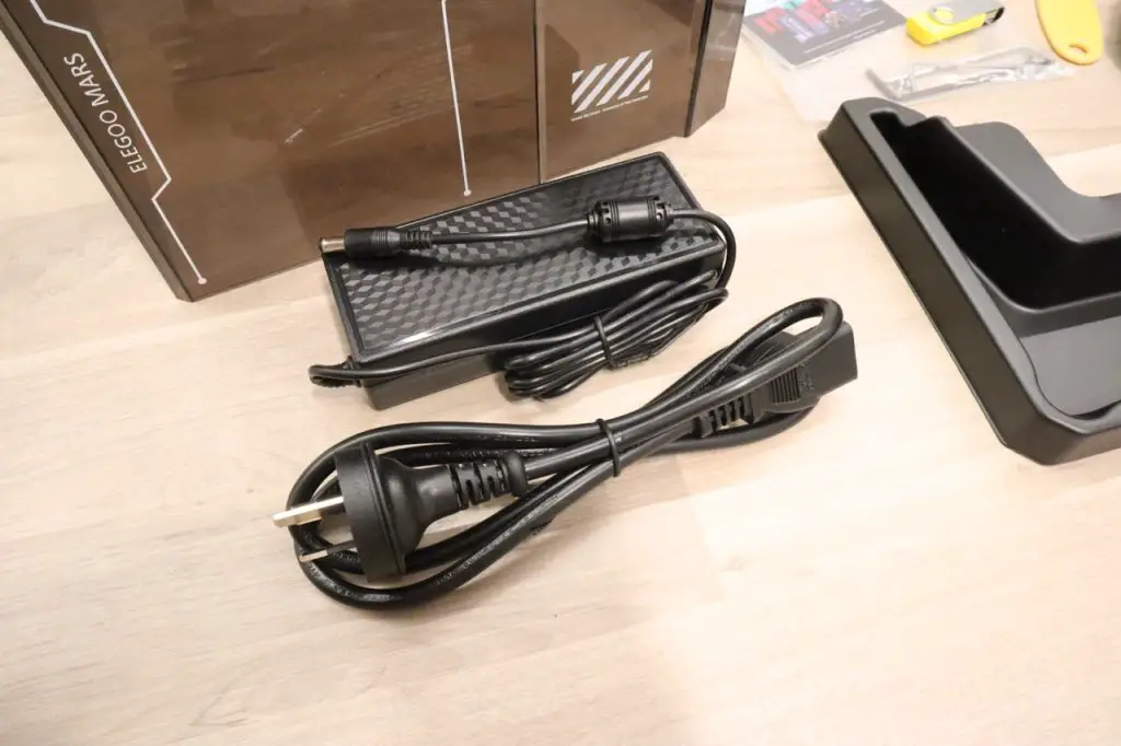
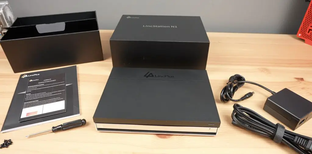
In the box, we’ve got the Delta 3 Plus Power Station, a quick start guide and three cables;
- A mains power cable
- A car charger cable
- A barrel jack cable
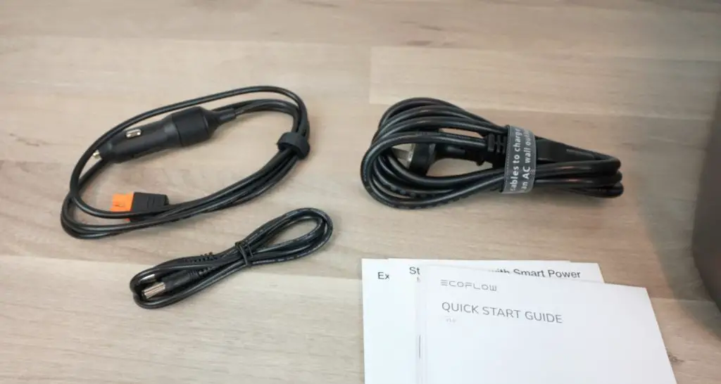
Unlike some other power stations, the AC charger is built-in, so you don’t need to carry a charging brick along too, so you don’t need any more than the power station and a cable or two to connect it up.
Inside the Delta 3 Plus is a 1024Wh LiFePO4 (Lithium Iron Phosphate) battery which is good for over 4000 full power cycles. If you used the full battery capacity every day, it would last almost 10 years and still have 80% of its original capacity.
The battery is also protected by a 3-layer system;
- The first is an IP65 battery enclosure which protects it against dust and splashes.
- The second is a smart battery management system that provides real-time monitoring and regulation.
- The third is a thermal runaway and fire propagation protection layer.
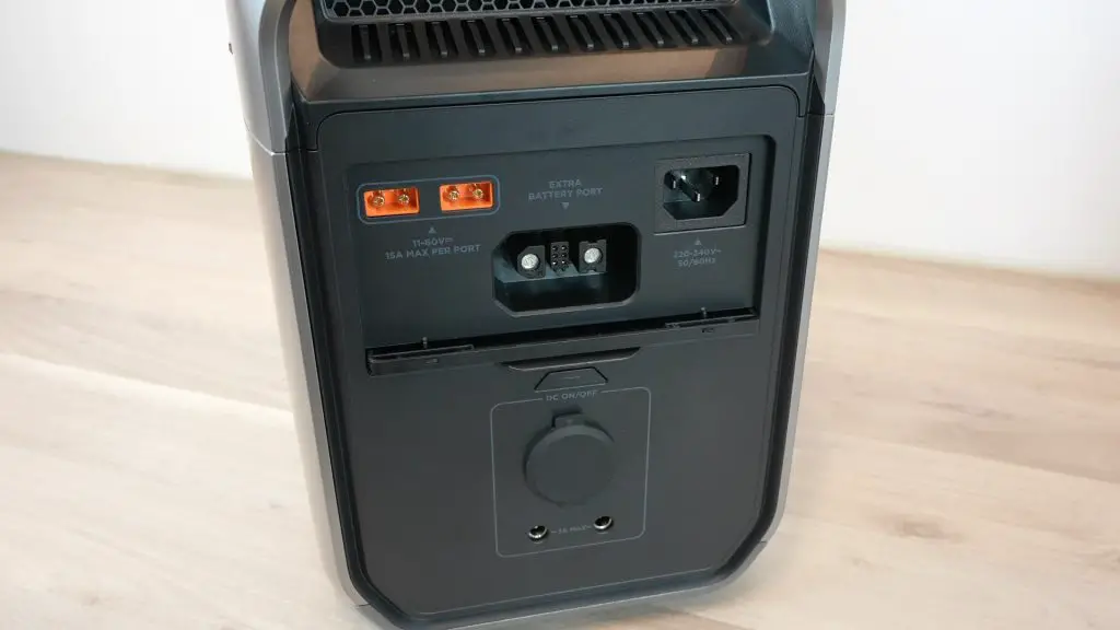
The battery is expandable up to 5kWh by adding compatible battery packs through the battery port at the back.

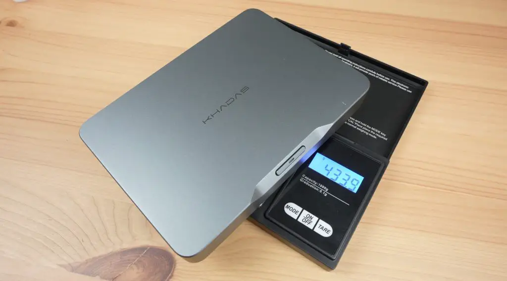
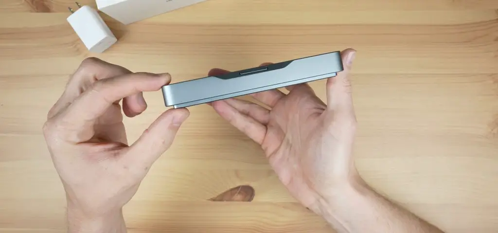
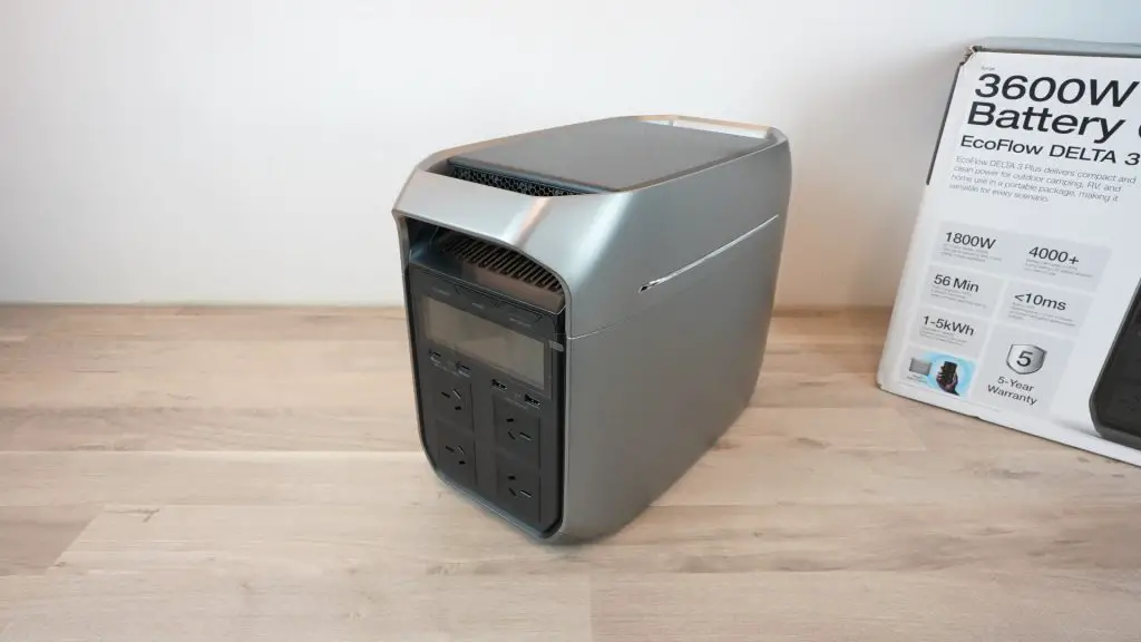
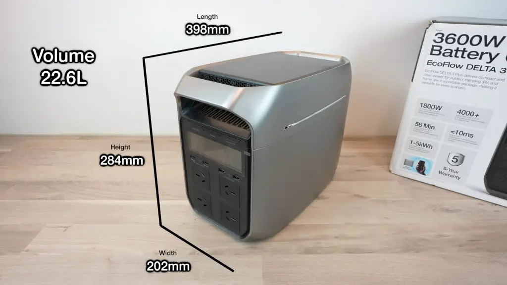
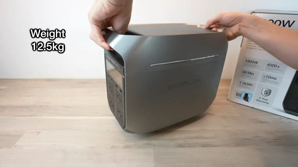
The Delta 3 Plus measures 398mm x 202mm x 284mm for a total volume of 22.6L, making it really compact for the features and battery capacity that it includes. It is about 5% smaller than the previous generation Delta 2 and packs in more powerful charging options. It is also relatively lightweight at 12.5kg.
Charging Options
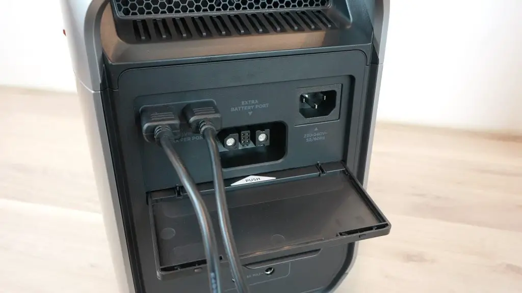
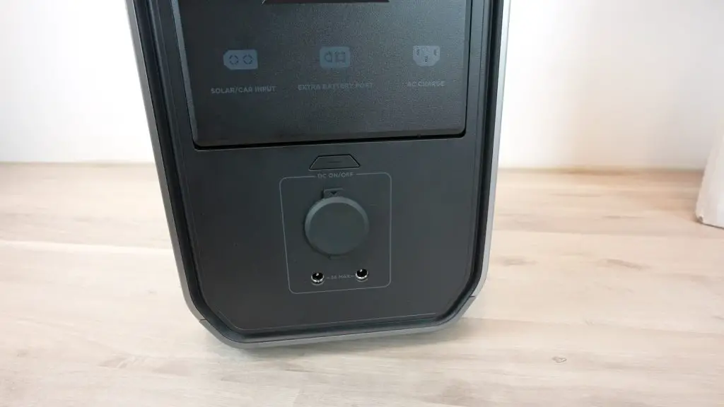
To charge the Delta 3 Plus up, you’ve got a couple of DC and AC options and they’re all under this newly designed cover on the back, which I quite like.
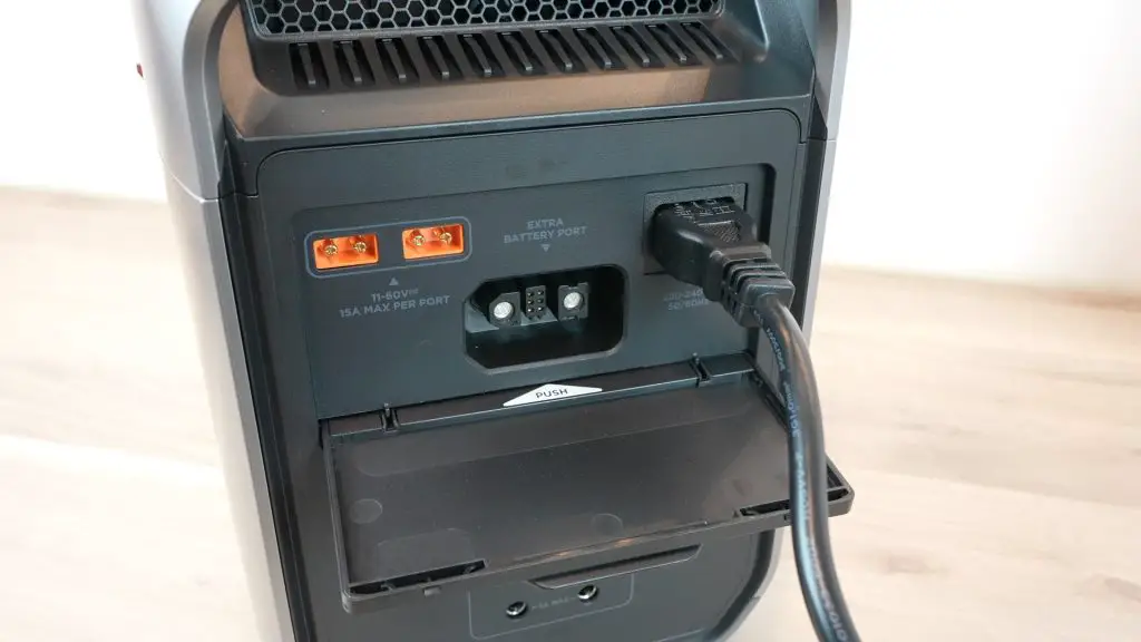
Using the built-in mains charger, you can charge the EcoFlow Delta 3 Plus at up to 1500W which will take it up to 80% charged in under 40 minutes and fully charged in under an hour – something that was previously only available on their River series.
So even if you’ve forgotten to charge your Power Station the day before your trip, you should still have enough time to charge it up while you prepare your things before heading out.
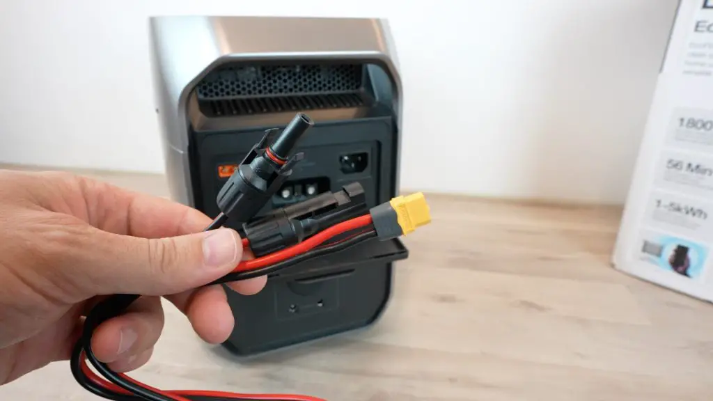
It has dual 500W MPPT charge controllers for up to 1000W of solar charging power. This will take the Delta 3 Plus up to 80% in under an hour, which is better than most of this size. The Delta 3 Plus doesn’t come with a solar charging cable, so you’ll need to buy this separately.
These DC ports can also handle up to 800W from your vehicle’s alternator to charge it up while you drive. Using the alternator input you can have the power station fully charged in a 2-hour drive.
You can also do a combination of charging inputs up to a total of 1500W. So if you have 1000W of solar input, you can increase the total charging input to 1500W by adding 500W of mains power too.
The cover on the back also stows away into the unit to get it out of the way, which is a nice design feature.
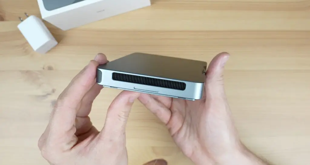
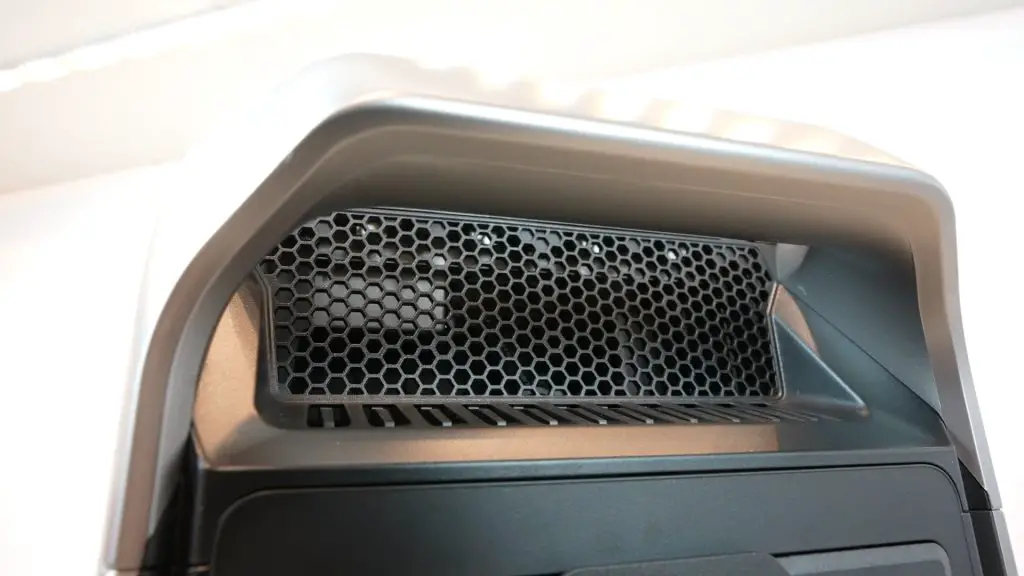
To keep the battery and inverter cool, there are some vents and a cooling fan at the top of the Delta 3 Plus. The fan isn’t always on though, it’s PWM controlled and only comes on under higher loads, particularly when charging or when supplying a high AC load, so it shouldn’t be very audible most of the time.
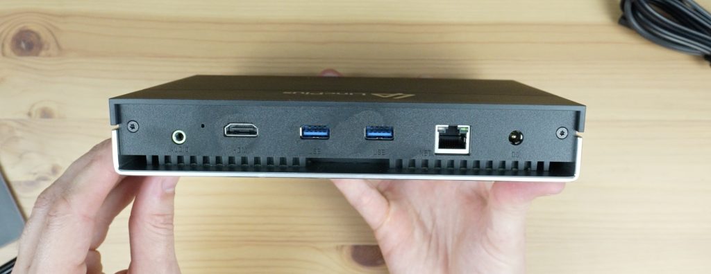
Power Outlet Options
To use the stored power, the Delta 3 Plus has a range of ports and outlets. The 4 AC outlets are powered by an 1800W pure sine wave inverter which can handle a surge of up to 3600W. Like with some other EcoFlow products, using their X-Boost technology, it can power some devices up to 2600W continuously. We’ll take a look at this a bit later on.
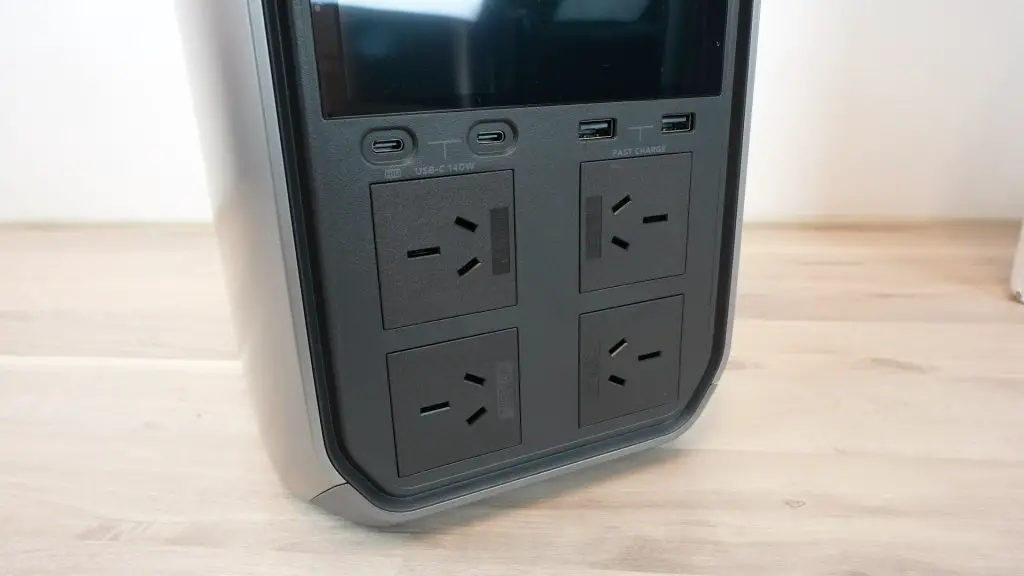
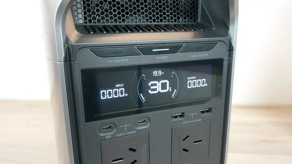
Above the AC outlets, it’s also got 4 USB ports, 2 USB type A ports that can do fast charging up to 36W and 2 USB type C ports that can do PD up to 140W.
And on the back under the charging ports, it’s got 3 DC outlets, 1 car power outlet which can do 12V at up to 10A and two barrel jack outlets which also do 12V but at up to 3A.
Other Features On The Delta 3 Plus
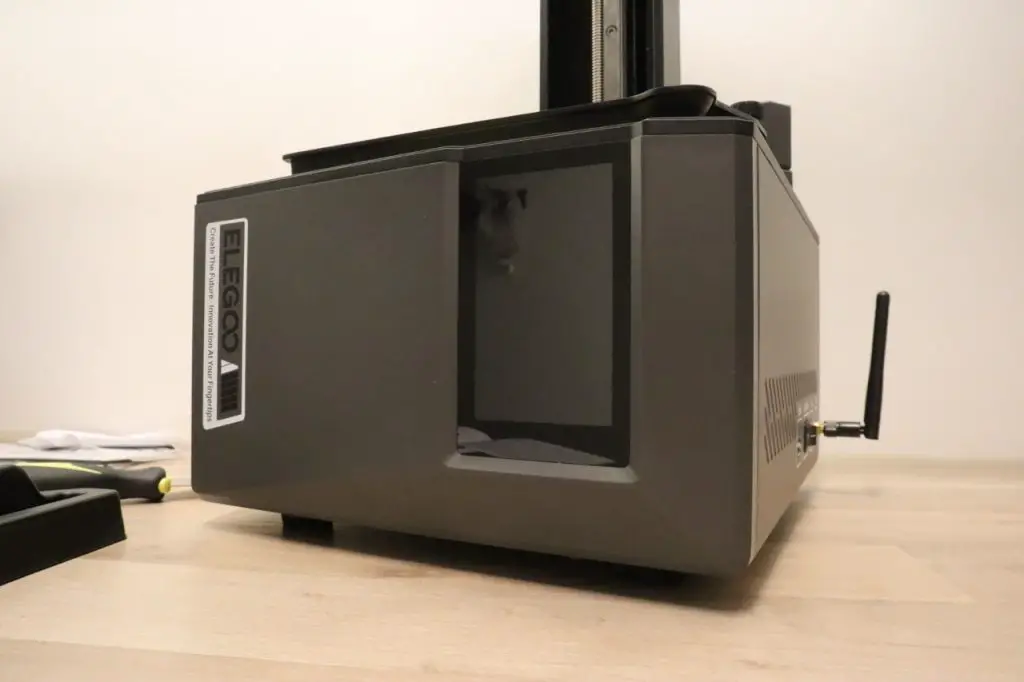
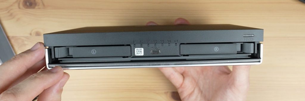
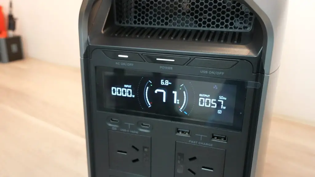
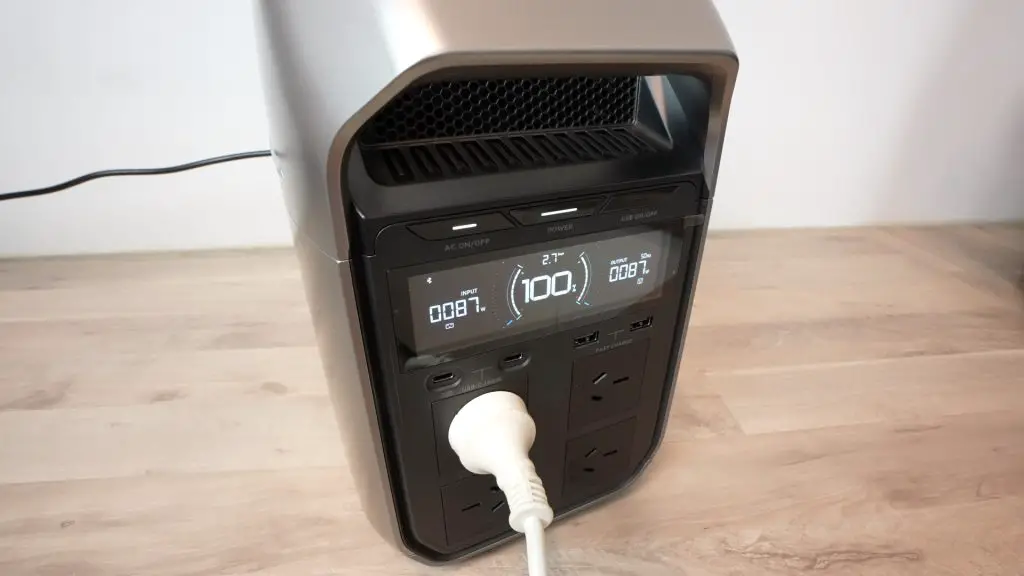
The display on the front of the Delta 3 Plus is similar to that on other EcoFlow models. It gives you a lot of information on the status of the device.
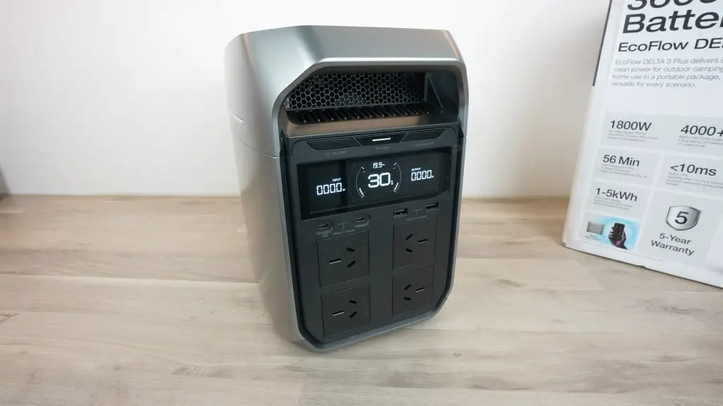
On the left, it shows you the total power input or charging power in watts, in the centre is the battery capacity within a power draw animation ring, on the right is the total power draw in watts and at the top is the time to fully charged or empty depending on whether the battery is being charged or drained.
Other small indicator icons come up when certain settings are activated.
The display goes to sleep automatically after 5 minutes by default but can be woken up again by pressing the power button. You can also change the sleep duration using the app.
Above the display are three buttons. The centre one turns the power on or off and puts the display into sleep or wake mode. The left and right buttons turn the AC and USB supplies on or off respectively. The button for the DC supply is at the back above the DC ports.
Now that we’ve had a look at the features of the Delta 3 Plus, let’s try to do some tests on it.
Testing Whether It Can Be Fully Charged In Under 1 Hour
It has currently got a 30% charge, so let’s get it drained completely and we can then test whether we can achieve an 80% charge in 40 minutes and a full charge in under an hour.
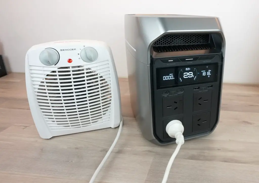
I’m going to hook up a small 1800w fan heater to it to drain completely.
The Delta 3 Plus stops the AC outlet when the battery is depleted to prevent over-discharge, but the battery management system and display remain active a little while longer.
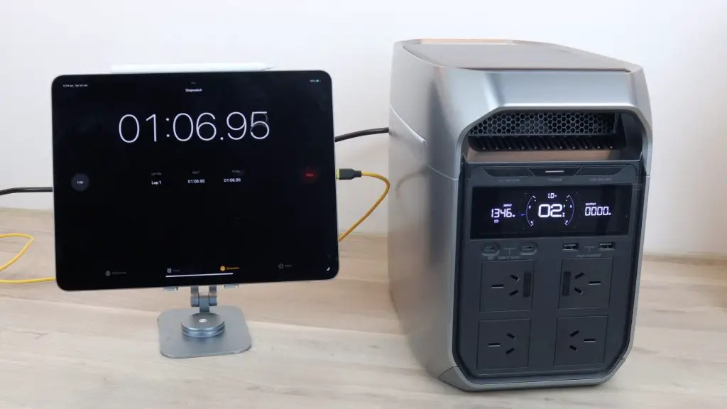
Next, I connected it up to the mains supply and timed how long it took to charge to 100% capacity. After a few seconds, the display indicated that it would be fully charged in 1hr. I checked in at 15 minutes in and the battery was 33% charged and the display indicated 35 minutes remaining, so it was on track to complete the charge in under an hour.
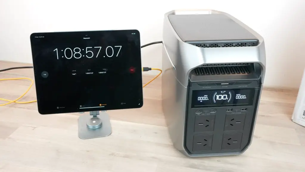
After 40 minutes, the battery was at 77% and after an hour it was at 94%. It was fully charged after 1 hour and 8 minutes.
So a bit short of the under-an-hour claim but it’s worth noting that this was in a workshop in summer in Australia so the ambient temperature is around 29 degrees, which reduced the charging speed a bit. A big part of fast charging a battery is keeping it cool, so if the ambient temperature is lower then you’ll be able to charge it faster.
Powering Some Other AC Devices
Now let’s plug some devices into it to test the AC supply.
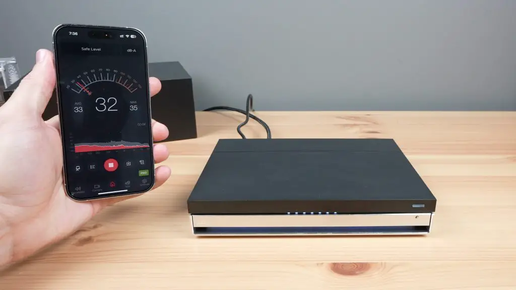
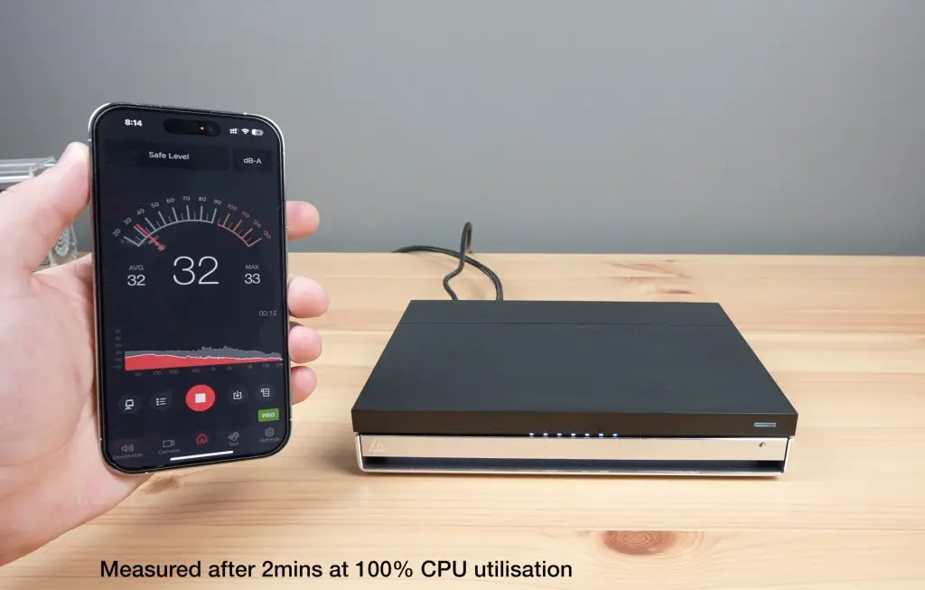
I’ve already shown the Delta 3 Plus powering an 1800W heater, but you couldn’t hear the Delta’s fan over the sound of the heater. So if I move the heater to another room and use an extension we can see how quiet it runs.
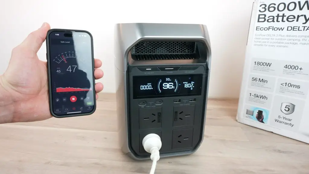
At full load, the fan ramps up almost immediately but it’s still fairly quiet, it stays at around 48db right within 10cm.
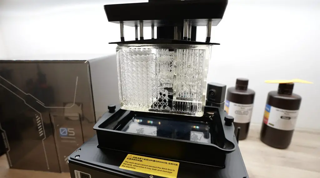
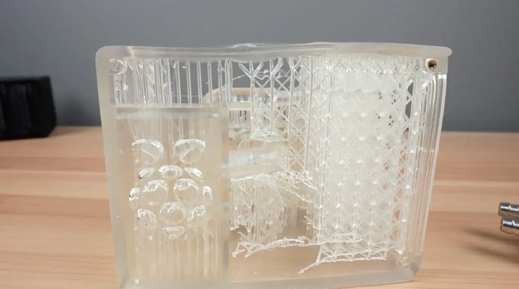
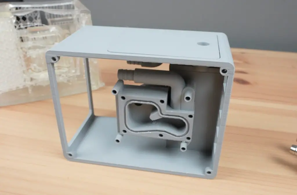
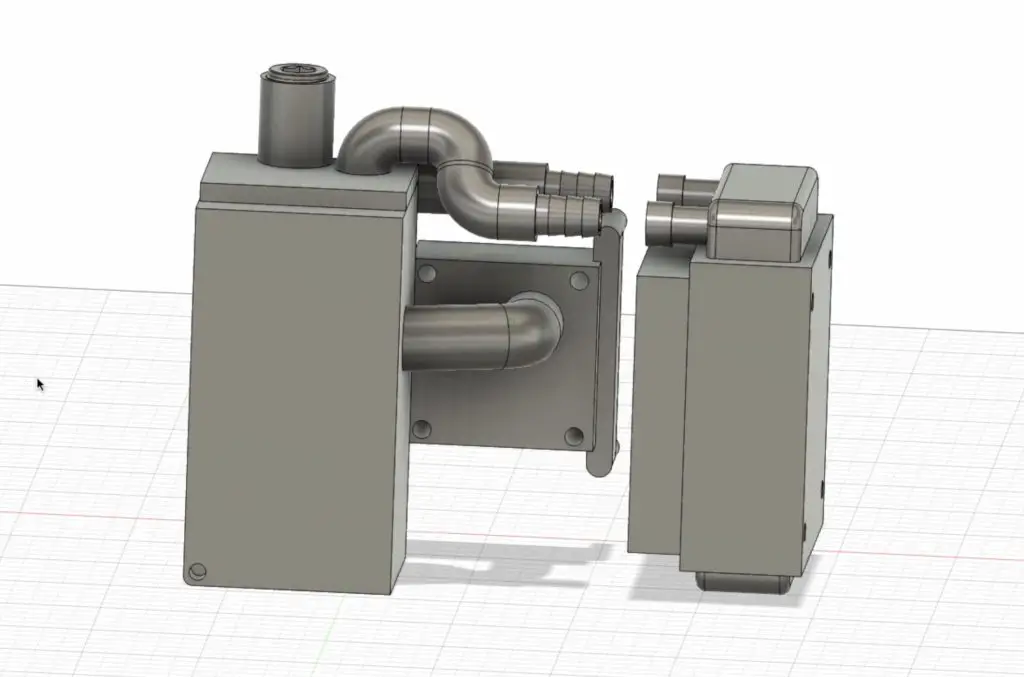
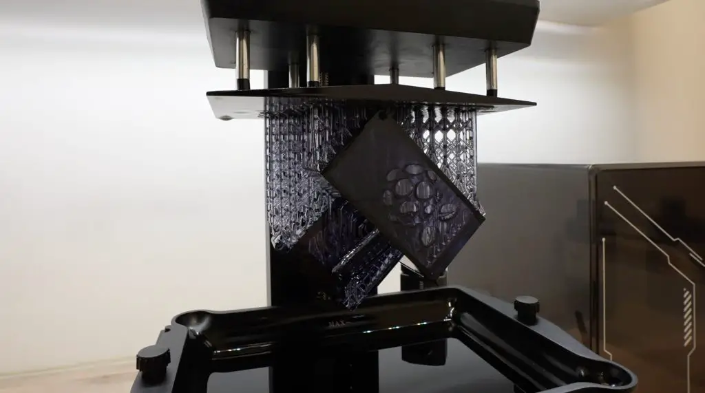
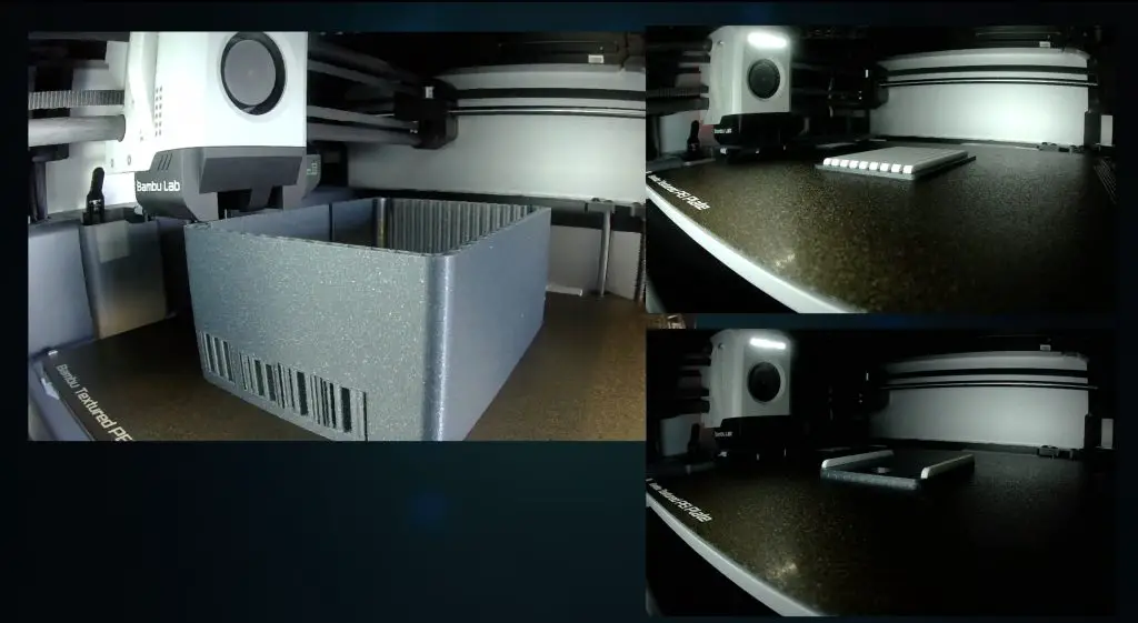
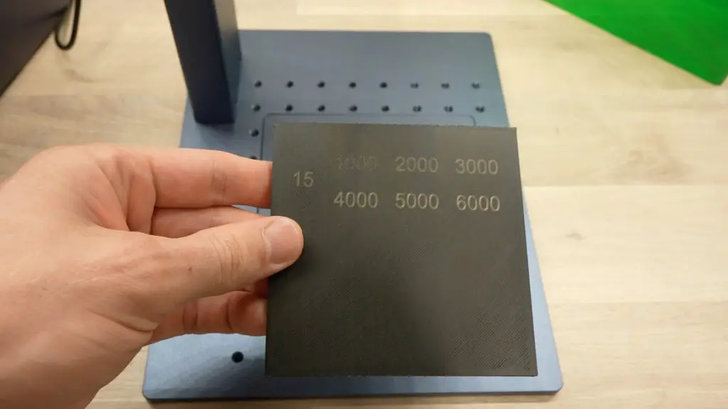
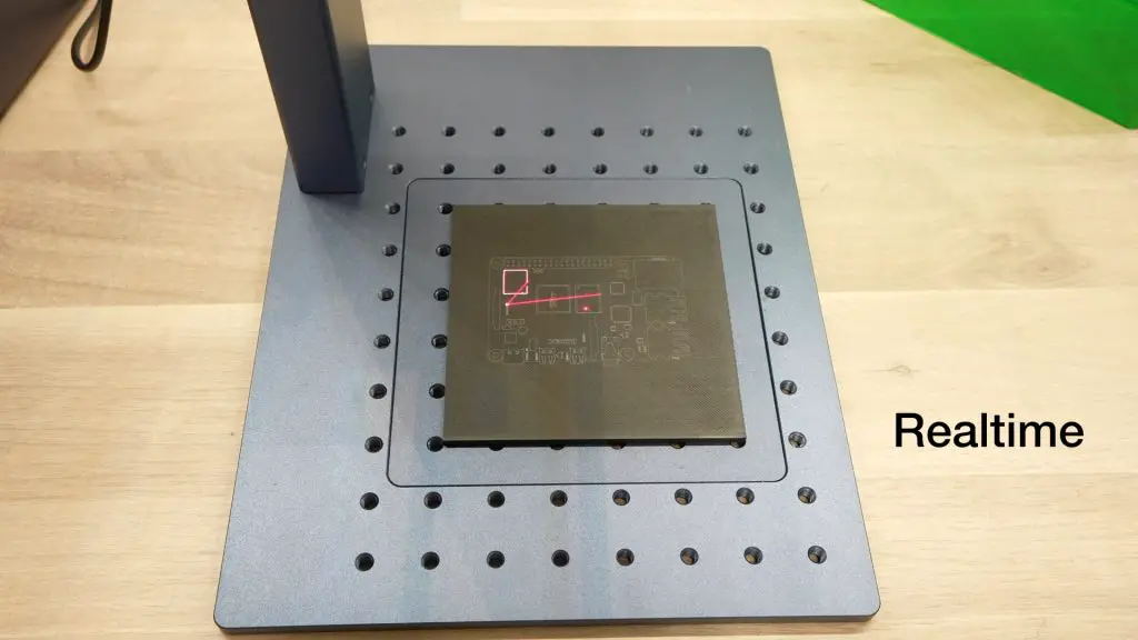
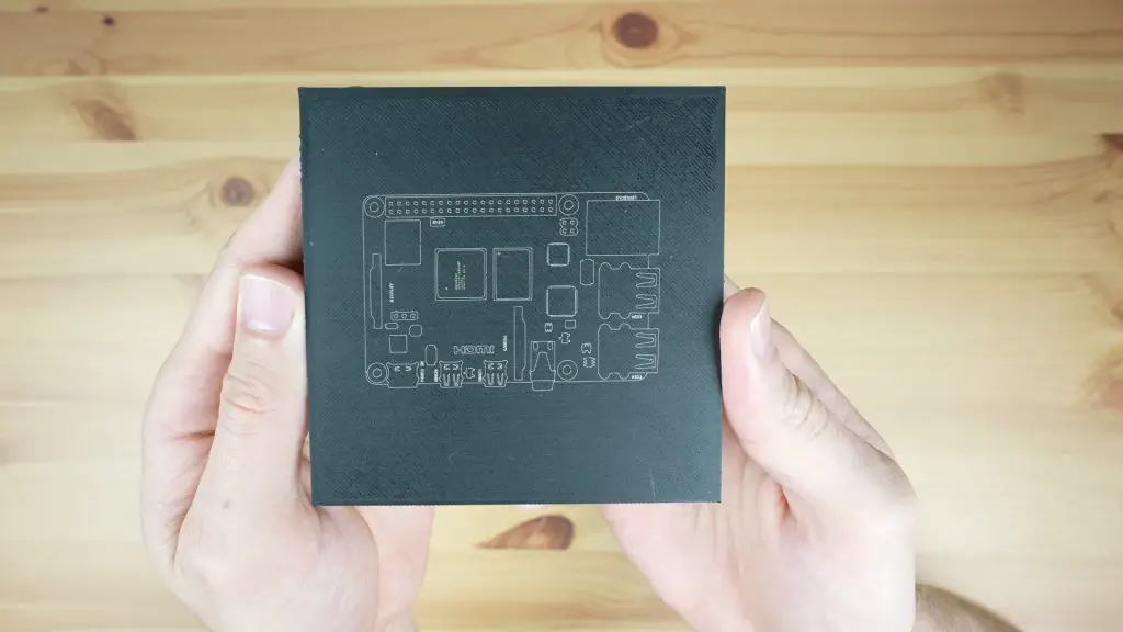
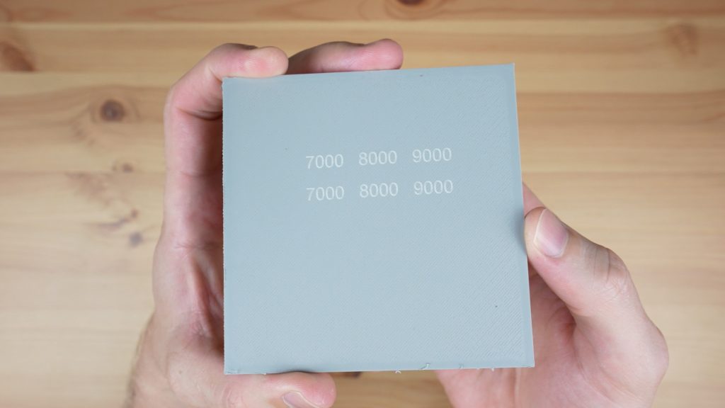
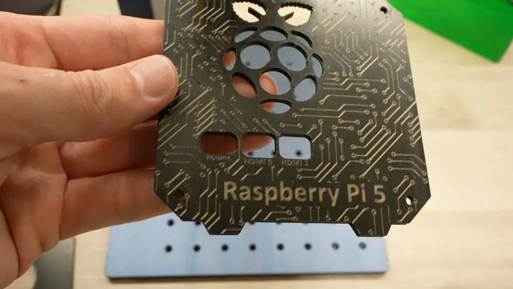
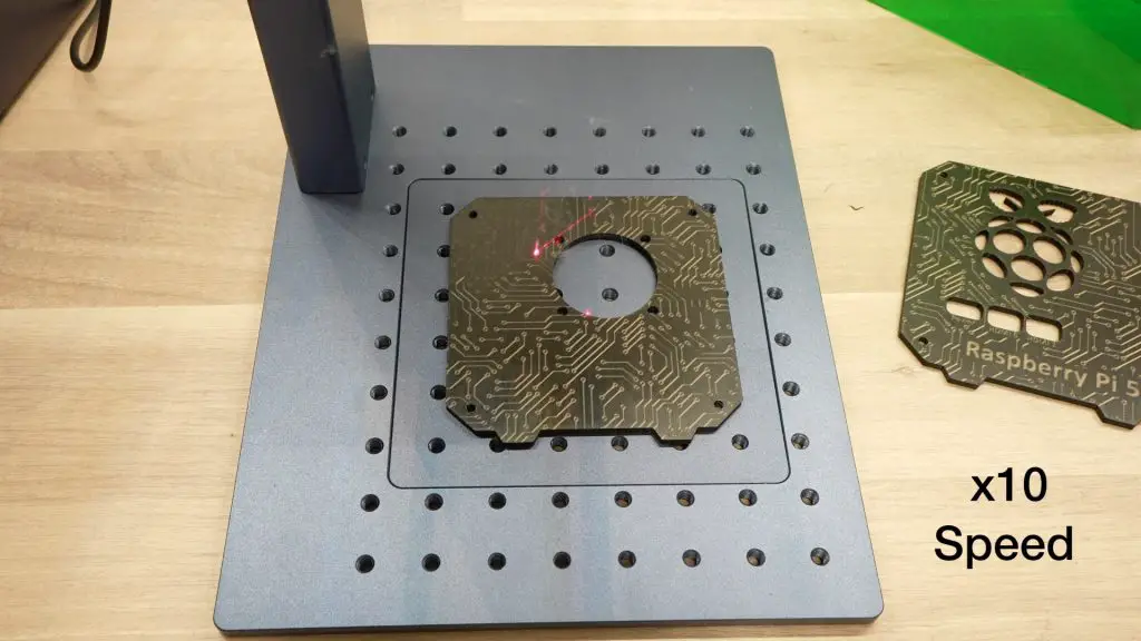
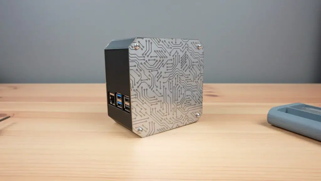
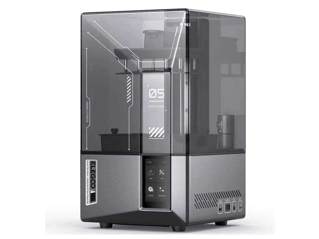
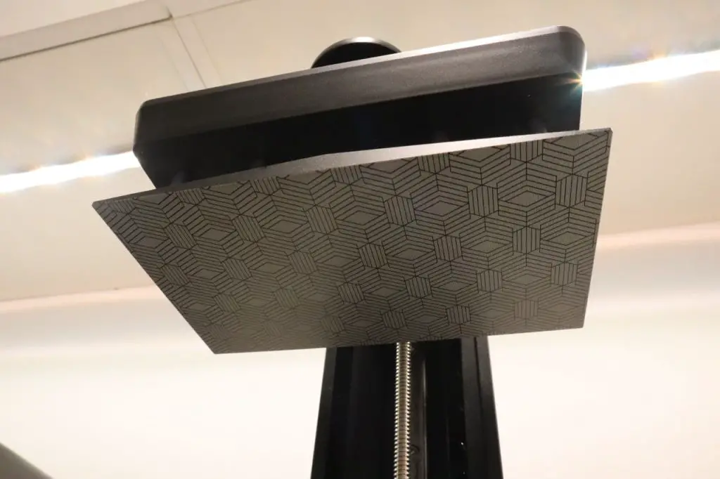
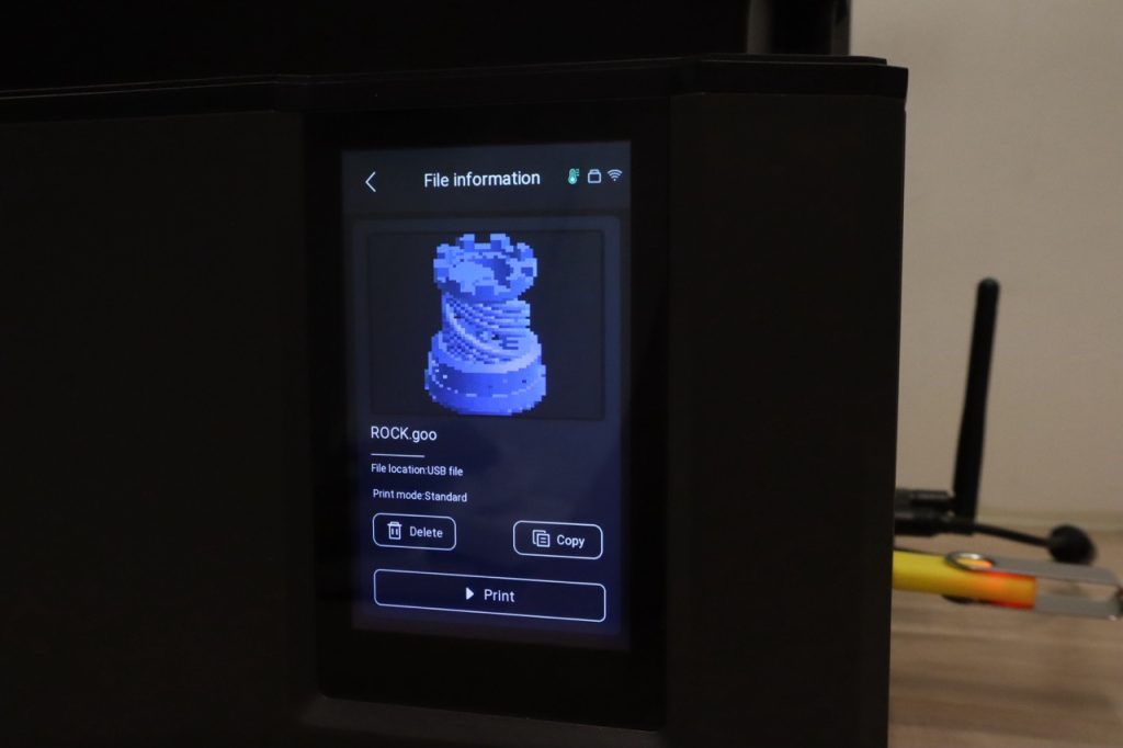
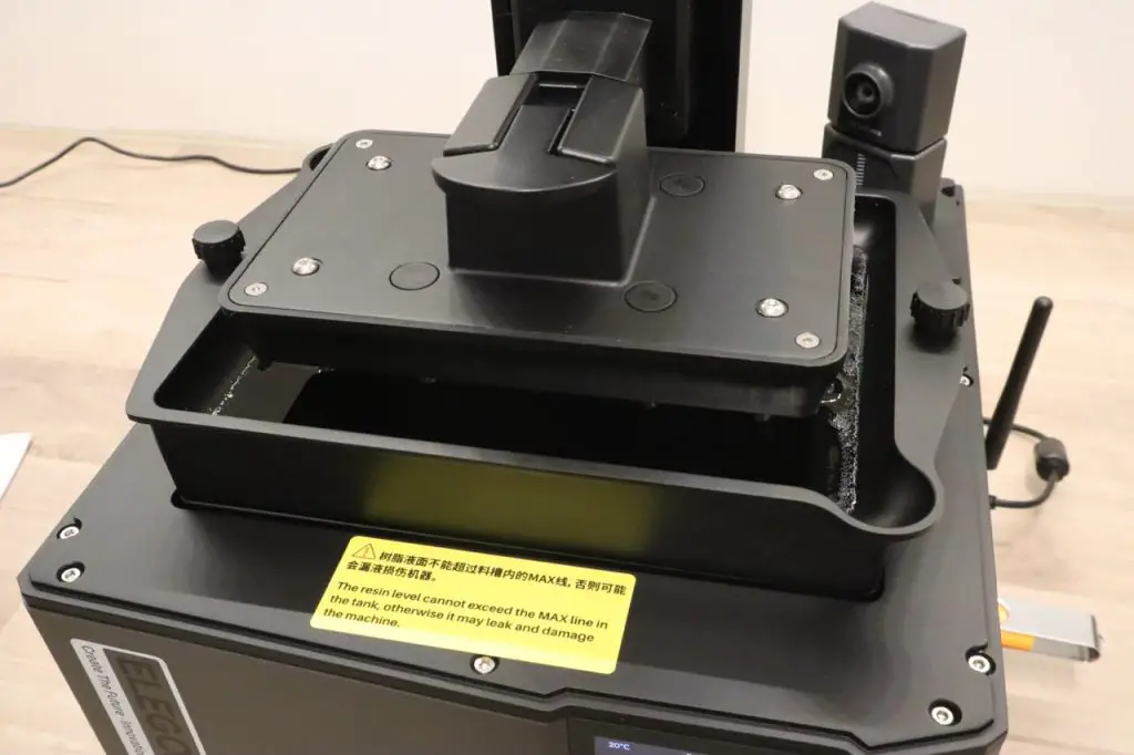
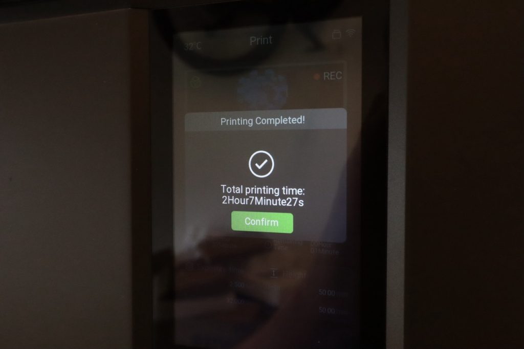
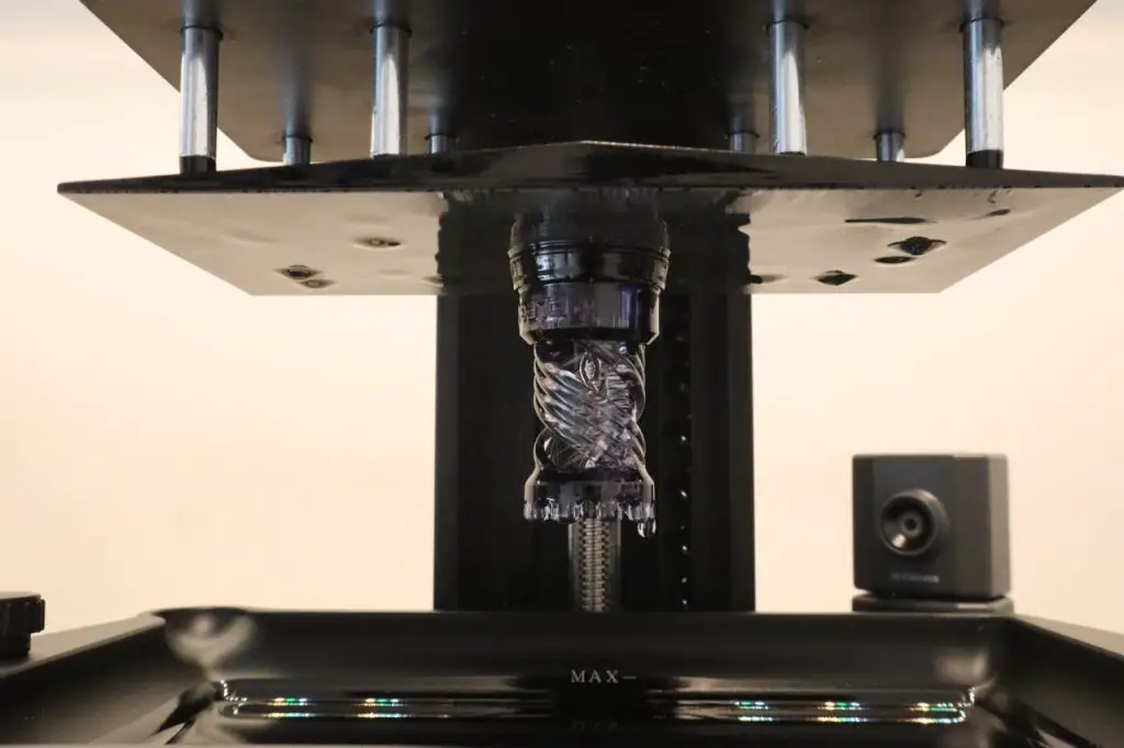
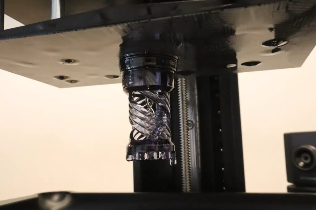
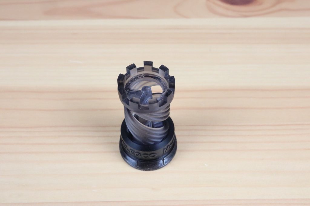
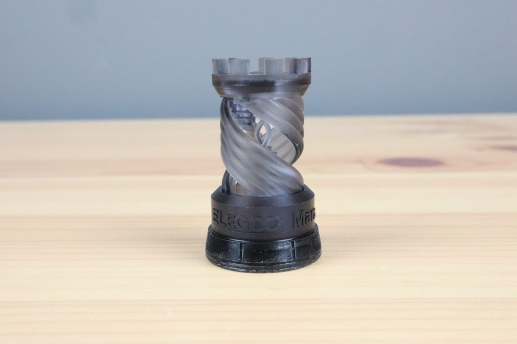
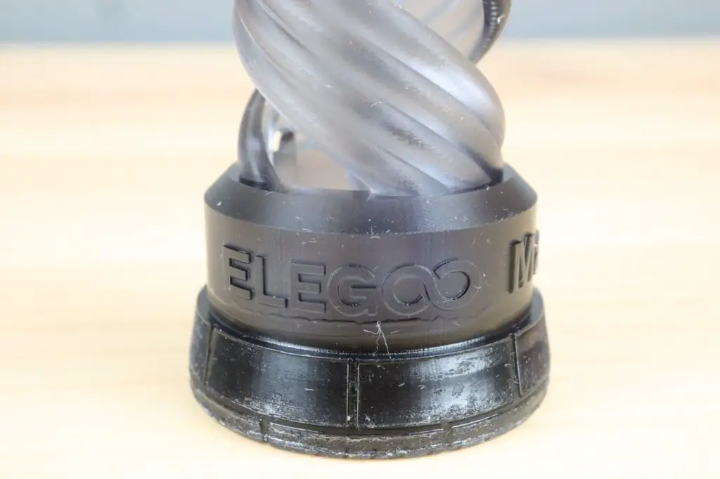
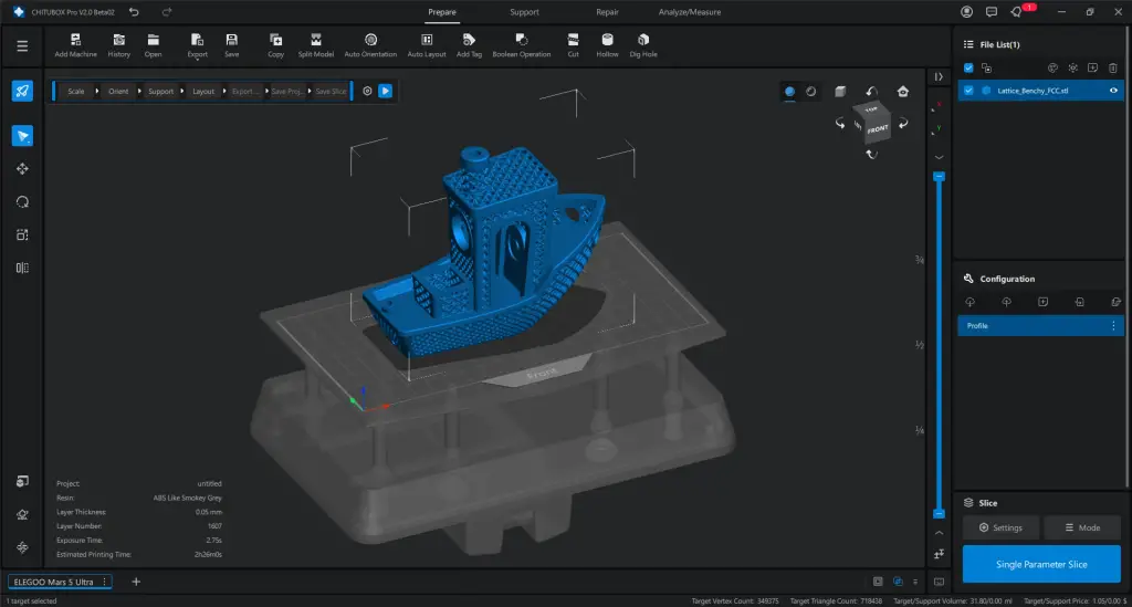
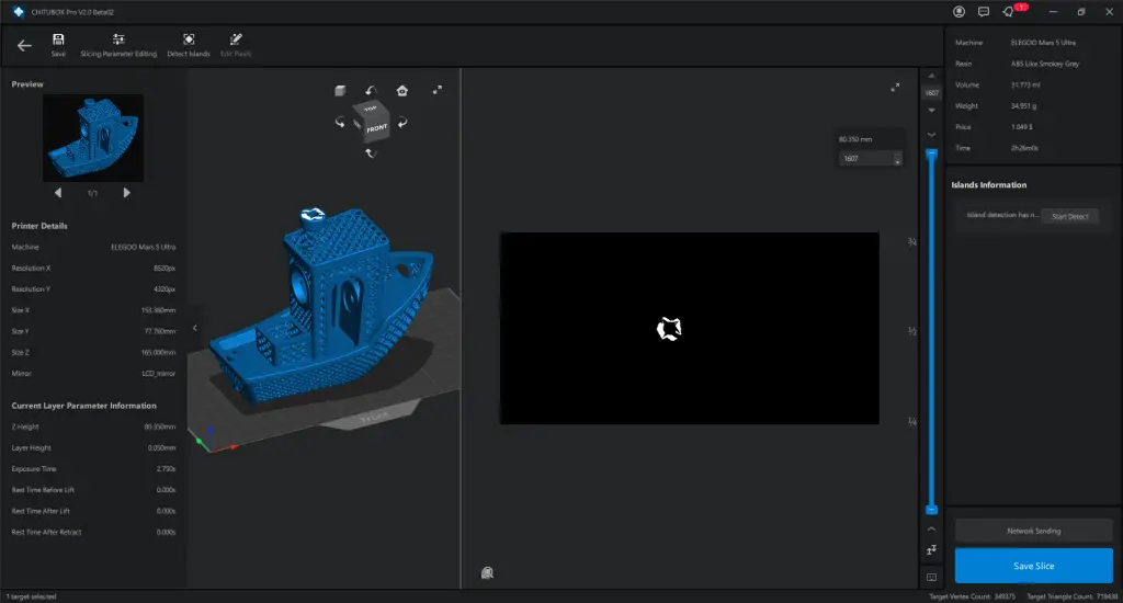
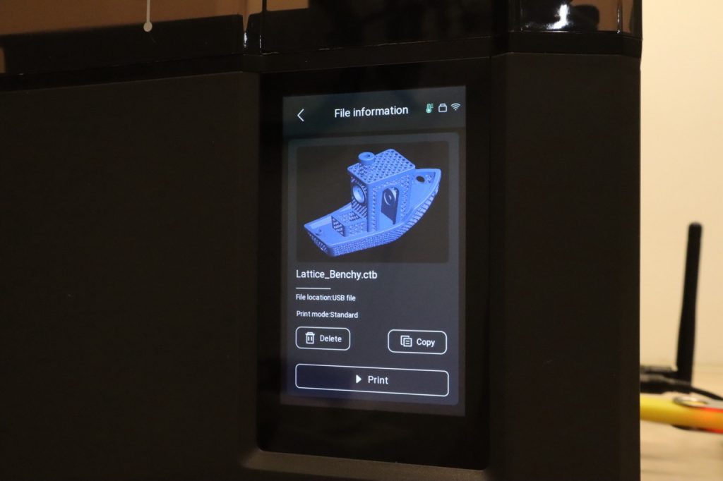
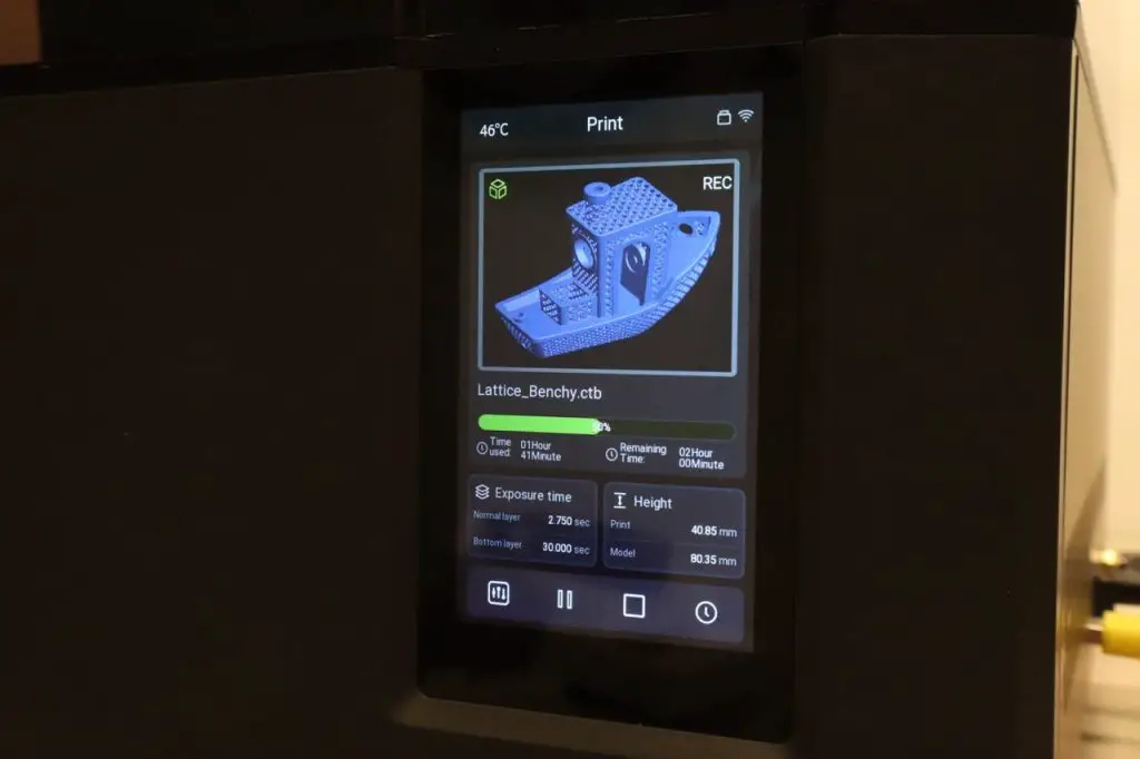
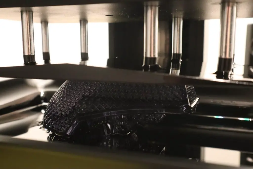
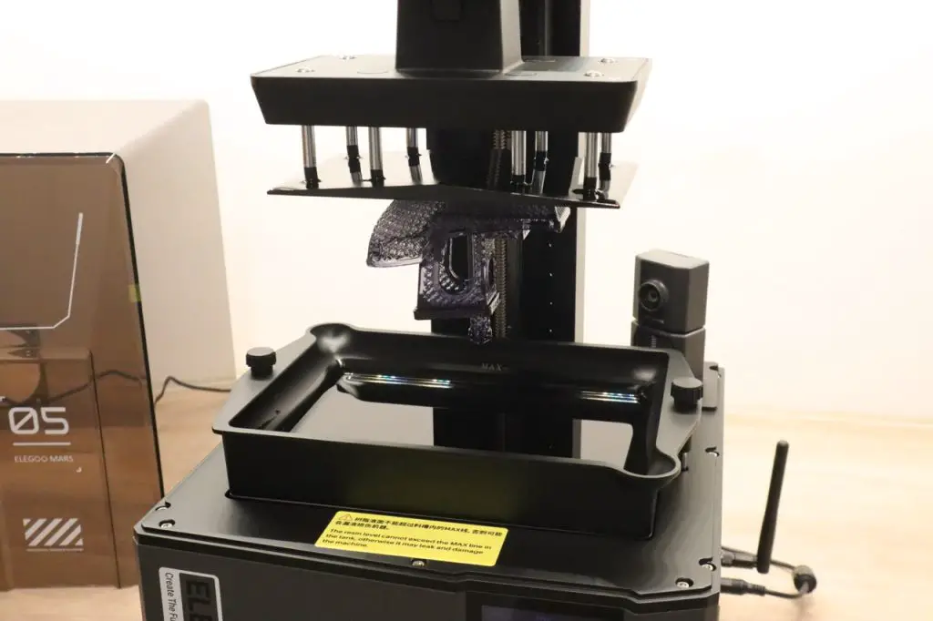
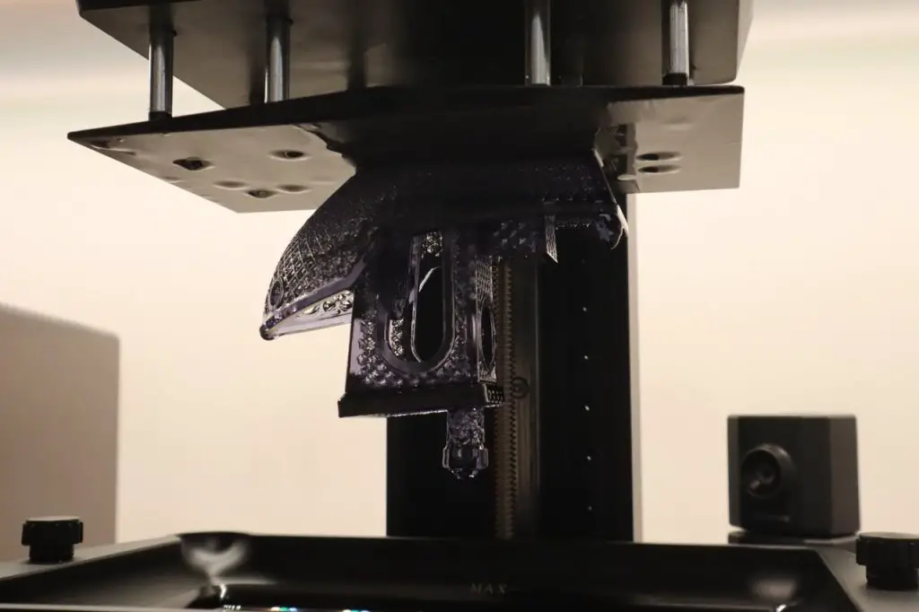
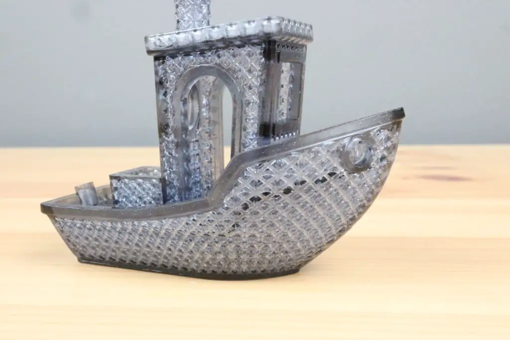
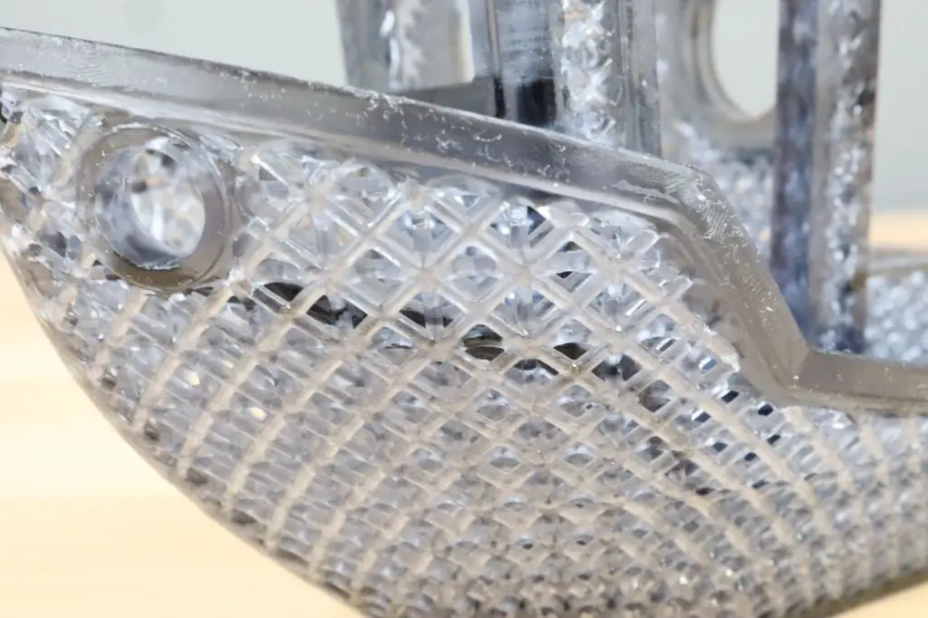
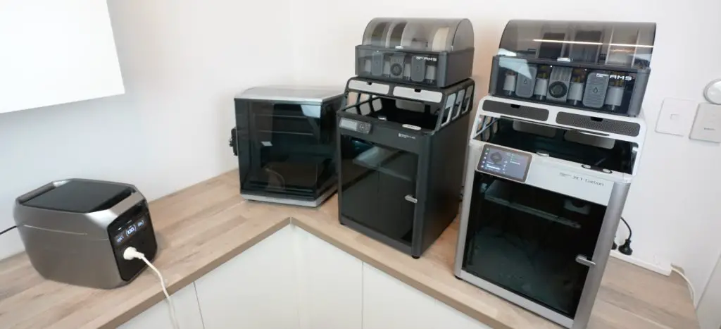
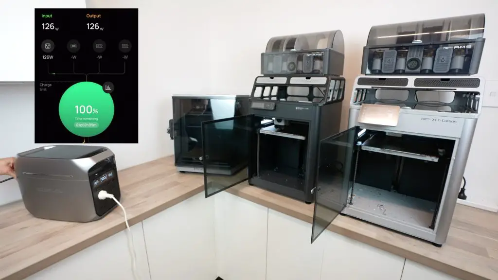
Next, I’m going to run my two 3D printers to print a vortex cube. These each draw about 500W when heating up and settle on an average of under 100W once printing.
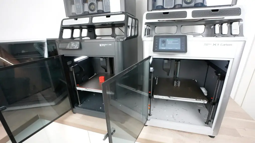
They ran for about half an hour to print both cube components and at the end, the Delta 3 Plus was at 71% capacity.

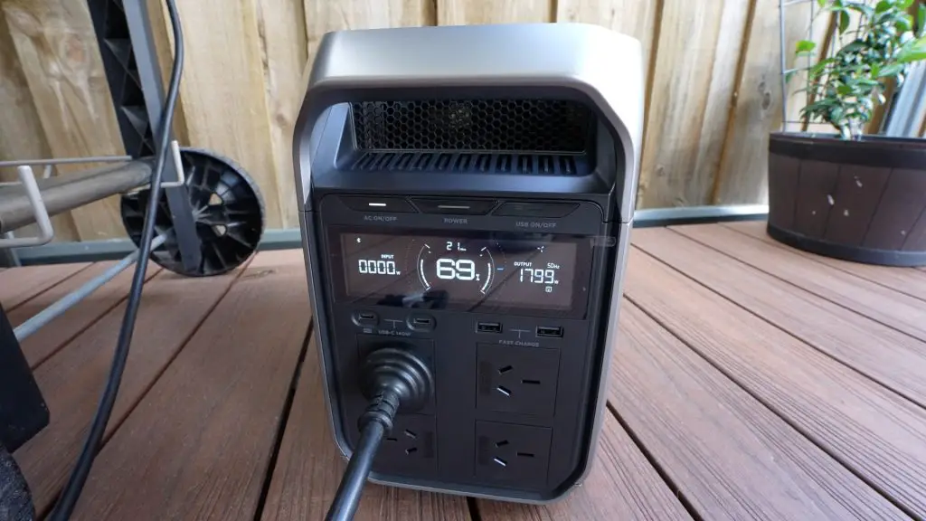
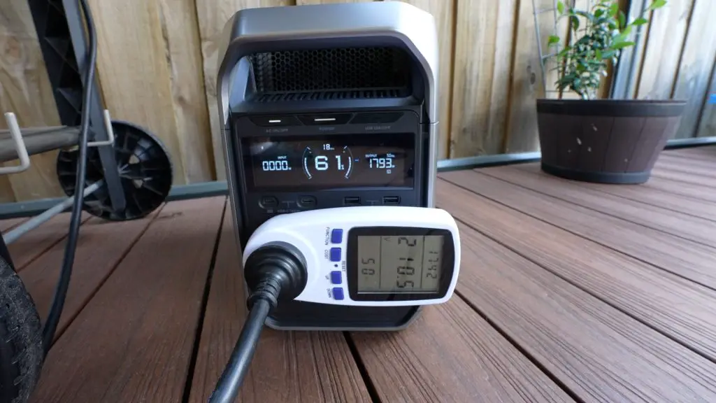
As I said earlier, the Delta 3 Plus is equipped with an 1800W inverter, but using EcoFlow’s X-Boost technology, they claim that you can run most appliances up to 2600W without overloading it. So I’m going to try to power this electric BBQ that draws a little over 2200W when turned all the way up.
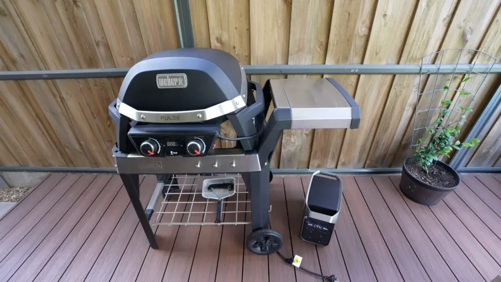
So the Delta 3 Plus is able to power the BBQ when it is turned all the way up, but you’ll notice that the power output is still only around 1800W.
X-Boost is able to power the BBQ on the highest setting by still only outputting the inverters maximum continuous power of 1800W. It does this by intelligently reducing the output voltage so that the inverter is not being overloaded but is still powering the appliance. Now obviously this is going to lead to a slight reduction in the performance of the appliance, but it does at least give you a way to use it. The BBQ will likely not get hot as quickly as it would on the full 2200W but it’s at least usable.
There are some limitations with X-Boost. Because it’s lowering the output voltage, which is common to all outlets, you can’t use it if you’ve got multiple devices connected to it.
You can also turn X-Boost on and off in the settings menu in the app if this is something you don’t want to use. It’s off by default.
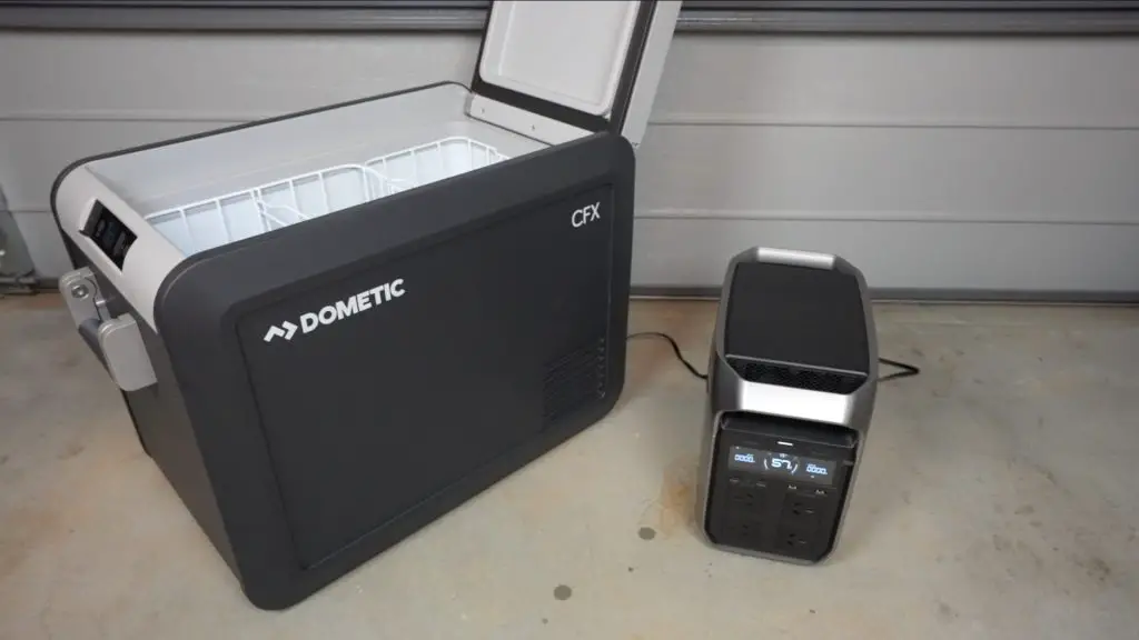
Testing The DC Power Options
Next, I tried the DC output on a small fridge that you would use for camping. That ran well as you’d expect and the display indicated that it could power the fridge for around 13.5 hours on the remaining 57% charge. It’ll likely land up being a lot longer than this as the fridge will draw much less power once it has cooled down to the target temperature.
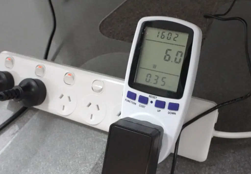
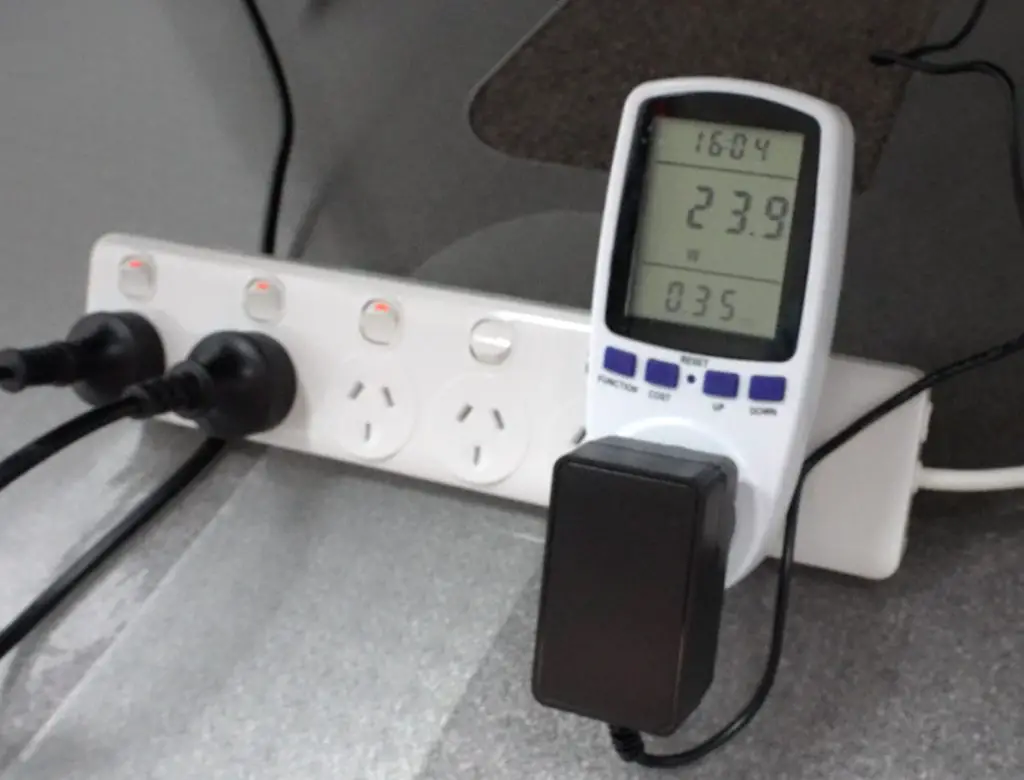
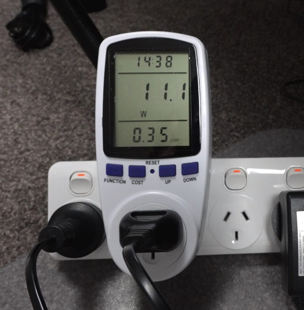
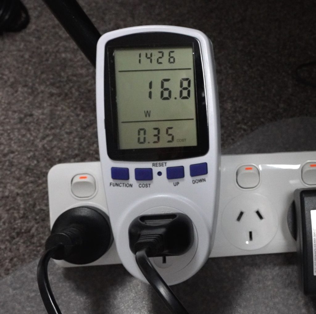
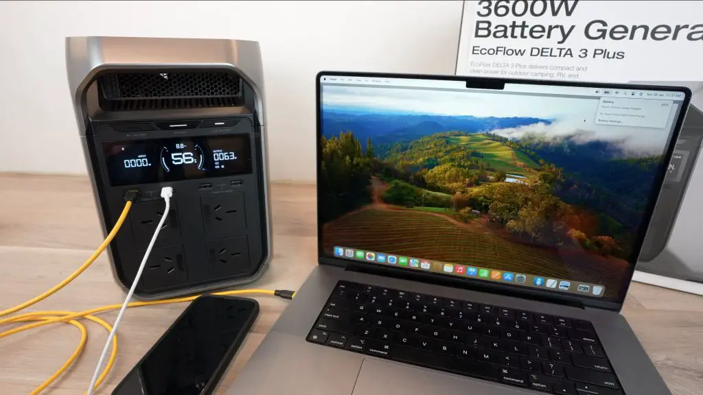
I then tried the USB C port to charge my MacBook and it indicated that it was charging at 50-60W because it was over 80% charged already. I added my phone and that increased the draw by another 7W but is still way under the rated 140W output for these USB C ports.
Testing The UPS Functionality And Changeover Time
One of the features I’m most interested in is the UPS functionality. My 3D printers and a desktop milling machine often run for long periods and a single short power interruption can cause failed prints or projects. So I’d like to put the Delta 3 Plus in line with their mains supply so that they’re kept powered through any interruptions.
The UPS on the Delta 3 Plus has a 10ms change over time, which is really fast for these style power stations. Most others have an advertised 20-30ms change over time so this is 2-3 times faster. Its 1kWh capacity will also be able to keep both printers running for 4-5 hours in the case of a longer interruption – which is really good for a UPS.
So I’ve got both 3D printers running off the AC outlets. I’ve used an adaptor because the printer’s power cables are quite short.
There are two important metrics to look at here. The first is the transfer or change-over time of the UPS, which in this case should be under 10ms and the second is the hold time of the device being powered. Because most electronic devices have power supplies with capacitors in them, they can usually handle a total power loss of a couple of milliseconds without the device turning off.
Both 3D printers are now running a print and are being powered through the Delta 3 Plus. Let’s pull out the mains supply to the Delta 3 Plus and see whether the printers notice it.
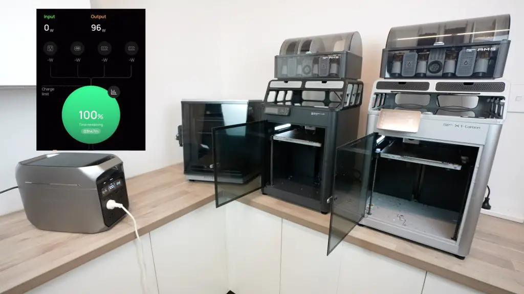
So both of the printers are still running with the mains power now turned off and they didn’t seem to mind the interruption.
When the power comes back on, the Delta 3 Plus changes back over to the mains supply.
I also connected a handheld oscilloscope to the AC output so that we could visualise the interruption to the sine wave to see what the transfer time is.
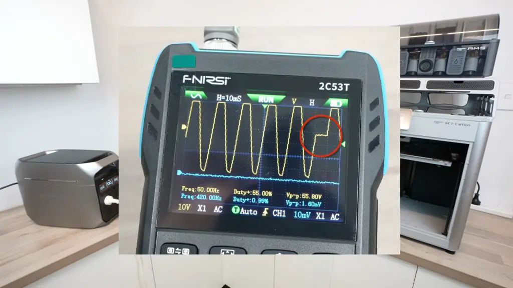
The interruption shows up nicely. We have 10 millisecond divisions and the flat line starts a tiny bit after the division starts and the sine wave starts again where the division ends. So the transfer time is a tiny bit faster than 10 milliseconds.
Another nice feature if you’re using it as a UPS long-term is to limit the maximum and minimum depth of charge, which is done through the app.
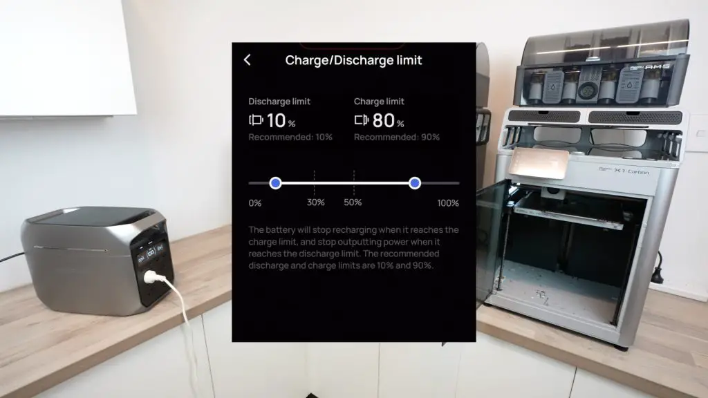
Limiting the maximum and minimum charge depth improves the longevity of the battery as you aren’t putting as much strain on it for each cycle.
Using The EcoFlow App With The Delta 3 Plus
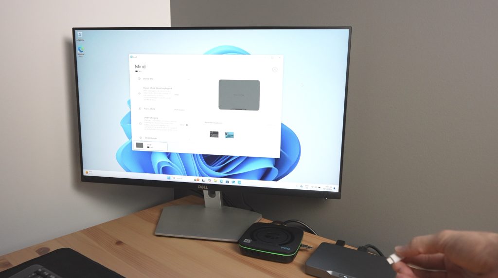
As I’ve shown a couple of times already, you can also connect the Delta 3 Plus to your smartphone through Bluetooth or WiFi to monitor and control it as well as change its settings.
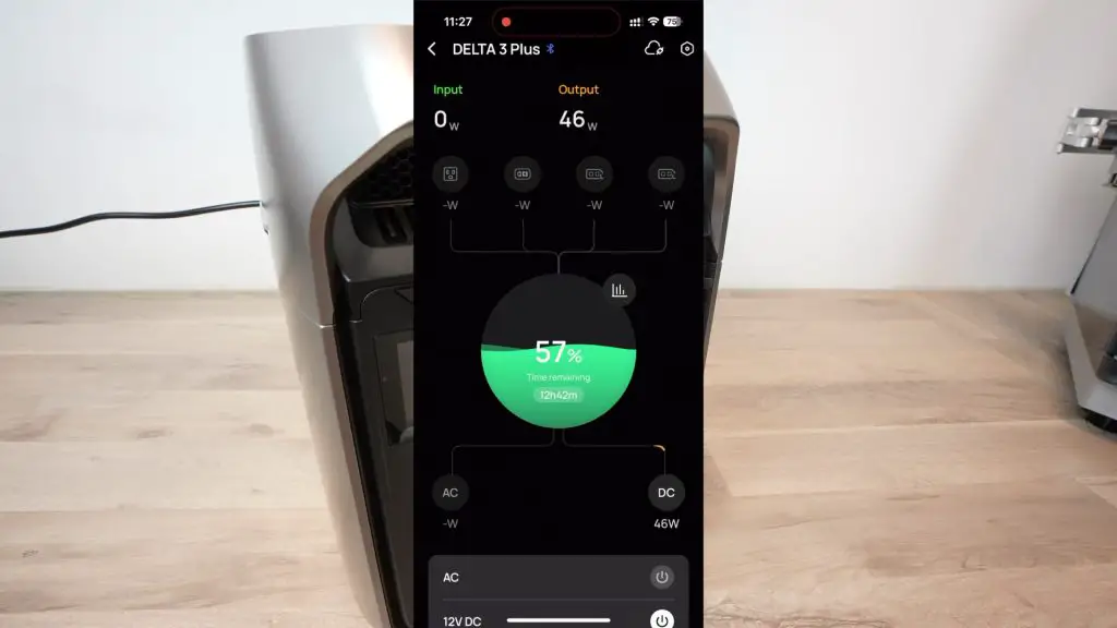
From the main screen, you can see the time remaining to fully charged or empty depending on whether the battery is being used or charged, you can also see the current rates of charge and discharge in watts of each individual port below that. You can turn the AC or DC inputs or outputs on or off remotely through the app as well. So you’ve got a lot of control through the app which is useful if it’s in a hard-to-reach place.
You can also access the device settings which allows you to do things like turn X-Boost on or off, set timeouts, manage charge and discharge levels and even reduce the maximum power that the power station can draw from mains when charging.
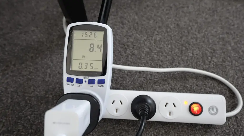
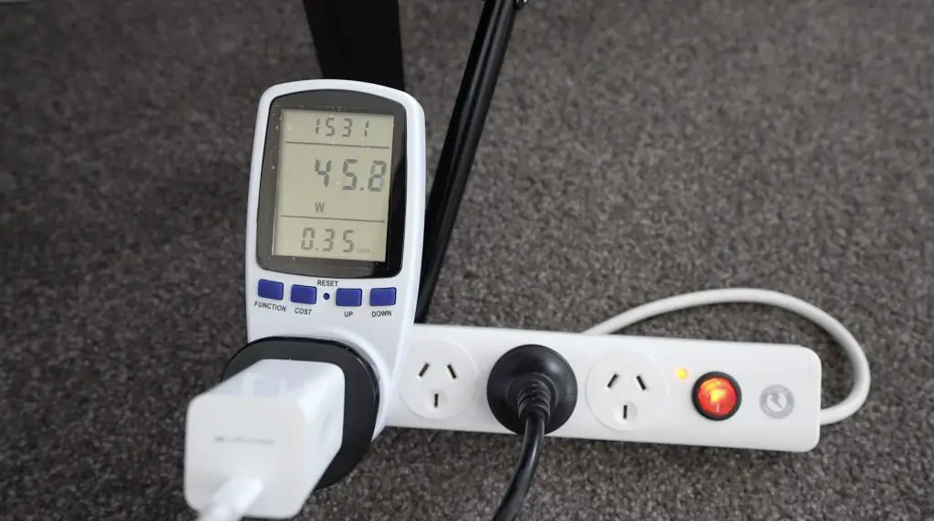
So if we turn it down to a maximum of 100W then it limits the mains charger draw to 100W.
This is useful if you’re at a campsite or charging it from another low-capacity power source. Without this, it’ll just trip or overload the device that you’re trying to charge it from.
It also has two presets, one for optimal battery life at 500W and one to keep the unit as quiet as possible during charging, limited to 200W.
It’s got similar options for the DC inputs as well, both set as current limits.
Final Thoughts On The Delta 3 Plus
Overall I’m really impressed with the Delta 3 Plus. Being a third-generation product, it is well-refined and has a good set of features. They’ve also made some nice ease-of-use adjustments over the original like moving the outlets to the front, adding the cover over the ports at the back and improving charging rates.
With the lithium iron phosphate battery, it should also last you around 8-10 years even with moderate use.
If you’re in Australia you can buy the EcoFlow Delta 3 Plus through their distribution partners like Anaconda, Total Tools, Autobarn, Harvey Norman or online from Amazon, eBay or from the EcoFlow website. The Delta 3 Plus comes with a 5-year warranty.
Let me know what you think of it in the comments section below and if there is anything else you’d like to see me test on it.