When the tap in the bathroom starts dripping at night and is making it impossible to sleep, here’s an easy fix to temporarily stop the maddening sound and allow you to get some shuteye.
Tie a small length of string around the aerator and allow it to rest in the basin. The water will now run down the length of the string and into the basin instead of dripping.
In the morning, you can tackle fixing the tap yourself or call in a plumber.
Do you want to build and control your own cloud storage? Here’s an easy guide to build a home based cloud storage solution that’s inexpensive and requires no coding experience, just follow these steps to get it set up.
The whole project takes about an hour to put together and set up and costs around $100 depending on the availability of components in your area/country
What You Need To Build Your Own Cloud Storage
Raspberry Pi 3
Western Digital PiDrive (314GB and 1TB available)
Micro SD Card (4GB or More)
Ethernet Cable
HDMI Cable (For Setup)
Monitor (For Setup)
USB Keyboard and Mouse (For Setup)
How To Build Your Own Cloud Storage
The building of your cloud storage system is done in two parts, the hardware needs to be connected and then the correct software needs to be installed and configured. The HDMI cable, monitor and USB keyboard and mouse are only required to do the software setup. Once the cloud storage is working, you can disconnect these devices. This allows the setup to use less power and fit into a smaller space.
Enjoy having the freedom to not carrying your bulky external storage devices and instead rely on cloud by accessing your files and media with a windows 7 virtual desktop on the go on your favorite mobile device. With 24*7 support from Apps4Rent.
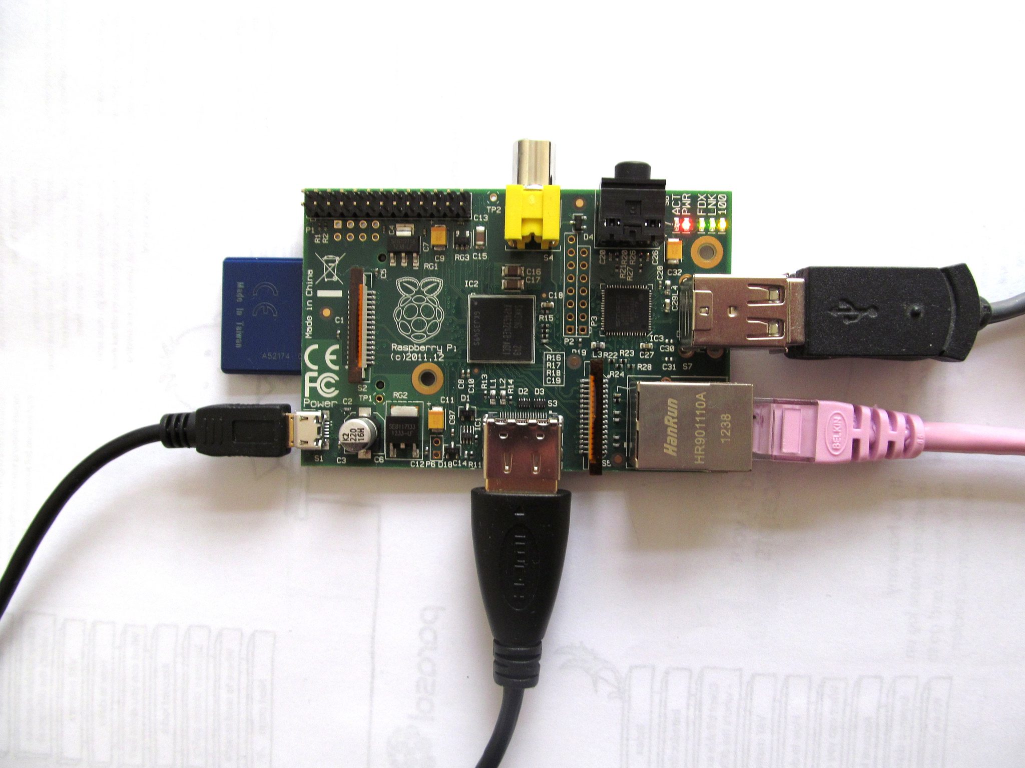
Connecting The Hardware
First plug the hard-drive into the Raspberry Pi. The hard-drive plugs into the mains and then connects to the Raspberry Pi via one of its USB ports. A micro USB plug is also provided on the hard-drive wiring harness to power the Raspberry Pi, plug this into the Pi’s micro USB socket.
Use the Ethernet cable to plug your Pi into your router to provide a network/internet connection.
Plug the monitor into the HDMI port on the Pi and the keyboard and mouse each into a USB port.
The microSD card plugs into the Pi’s card reader, keep it for the time being as you need to load software onto it before plugging it in.
Loading the Pi’s Operating System
Plug the microSD card into your laptop’s card reader or using an adapter.
Go to raspberrypi.org and download Raspbian NOOBS which will then install the Pi’s Linux based operating system. In the NOOBS folder there is a file called INSTRUCTIONS-README.txt, follow the instructions in this file to load the operating system onto the microSD card.
Plug the microSD card into the Pi and then power up your Pi via the hard drive.
The monitor should now take you through instructions to install NOOBS which takes around ten minutes or so.
Configuring the Cloud Storage
Now you need to configure the Raspberry Pi to tell it how to manage the storage on the hard-drive. This will be done through the Pi’s command prompt system, it may seem confusing at first but if you follow the instructions presented below paying careful attention to the syntax, it’s really quite easy.
Click on Menu > Accessories > Terminal. A black window will pop up which allows you to type and enter commands. Throughout the commands listed below, <Enter> denotes pressing the Enter button on your keyboard.
Start by typing:
dmesg | tail -n20 <Enter>
You will get a reply which looks like this: [5.860566] sd 0:0:0:0: [sbc] 1953547193 512-byte logical blocks: (1.00 TB/931 GiB)
In this case, the drive name is sbc but yours may be sda or sdc, change the name accordingly below and type in:
sudo mkfs.ext4 /devsda -L “Data” <Enter>
sudo mkdir /mnt/data <Enter>
sudo mount -t ext4 -o “noatime” /dev/sbc /mnt/data <Enter>
sudo mkdir /mnt/data <Enter>
sudo nano /etc/fstab <Enter>
Please the down arrow to move the cursor to a new line, then type in this:
And then save what you have done by pressing these keys in order <ctrl + x>, <y>, <Enter>
Find your Pi’s IP address by typing ifconfig <enter> into the terminal as you have just done for the setup. One of the fields will be inet addr and then a number like 192.168.1.3, this is your Pi’s IP address.
On your computer (PC or Mac) connected to the same network, open your web browser and enter the Pi’s IP address: http://192.168.1.3:8888/gui. Follow the prompts given on screen and setup an account. When you get to the main account page, click on Add Folder and choose the folder you created called /mnt/data, this is a folder on your PiDrive. Make sure the the Read & Write box is checked which allows other devices to access it. Leave this browser window open.
Open another browser window and go to: https://get-sync.com/platforms/desktop/. Install the app and open it. Now go back to the browser window with Sync open to Share -/mint/data. Click copy and then paste that URL into a new browser window. This URL will open your Sync desktop app and add your /mnt/data folder to it.
Approve the Sync request from your control panel (the one you copied the URL from) and it’s complete. If you’d like to upload files from your phone or tablet, download the Sync app and open the copied sharing URL or QR code on your desktop. You’ll need to approve it on the new devices as well.
You can now send files to your personal Cloud Storage from anywhere.
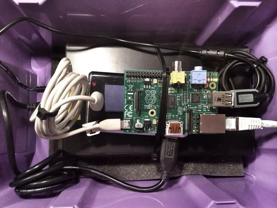
Here’s a working Raspberry Pi cloud storage server which has been built into a small storage container:
Have you been looking at becoming a home owner or buying a larger property which may require you to take out a home loan? In the last couple of years, banks and financial services providers have become increasingly stringent on the application process and their lending criteria. Applicants need to have their financial affairs in order before thinking of applying for a loan.
If you have made a resolution to buy a new home in 2017, you will need to have access your financial situation and asked yourself these six important questions before approaching your local bank for financial assistance. Some countries have much stricter credit and lending regulations, however, at the moment less than 50% of all bond applications are actually approved, mainly due to missing information or applying for more credit than you are able to afford.
So Here Are The Questions To Ask Yourself Before Applying For A Home Loan
What’s My Credit Score?
You may have heard the term “credit score” before, your credit score is an indication of how good you are at borrowing and repaying money. A good credit score and credit record are extremely important in the application for a home loan since it is a high value transaction. Depending on your country, your national credit bureau should be able to issue you with a credit report and your subsequent credit score.
You credit score is influenced by a number of factors, some of which include: missing repayments, opening too many accounts, only paying the minimum repayments etc. All of these affect your credit score and may deter potential lenders, especially with high value transactions.
What Is My Annual Income?
The maximum bond amount you can apply for as an individual or as a married couple is most likely based on your individual or combined annual income. When stating your annual income, remember to include items such as rental income, performance bonuses and investment returns. Your annual tax return is an important document which should provide a comprehensive list of all of your income sources.
What Debt Do I Currently Have?
After banks have looked at your annual income, they will calculate what your “disposable income” is. You will have to provide your bank with a list of all of your monthly payment commitments, repayments on credit cards, vehicles, insurance, taxes and rates, levies etc. The bank will then calculate your debt to income ratio which is used to determine your affordability, an individual with too much debt is a higher risk to banks than one with very little debt.
Try to pay up as much of your outstanding debt as possible before applying for a home loan to improve your affordability and improve your chances of your bond being approved.
What Is My Net Worth?
The bank will then look at your “net worth” which is calculated by adding up the value of all of your assets such as vehicles and houses and the subtracting any outstanding debt you have. The difference is your net worth or the amount of money you would have if you sold all of your assets and settled your outstanding debt. A higher net worth means that you are less of a risk to the bank as you will be able to pay back any shortfall should something happen to the property.
There is not much you can do to improve your net worth significantly in a short period of time.
What Deposit Can I Afford?
Depending on your country, banks will likely require first time buyers to put down a deposit when purchasing a property, this is typically around 10-15% of the purchase price of the property at the moment.
When working out how much you can afford to put down as a deposit, remember to include cash which you have available now as well as any money you will make on the sale of existing property or assets before you buy the house. Remember to subtract transfer fees, bond costs and lawyers fees applicable as these will be payable soon after the acceptance of the offer to purchase.
What Monthly Loan Repayment Can I Afford?
Before you even start looking at houses you should have an idea of what you can afford to repay monthly. It is easy to get an idea of what sort of price range you can look at by using an online bond repayment calculator.
Typically, your monthly home payment which includes the bond, interest, taxes and insurance should be less than 30% of your monthly income. Any more than this and your bond will likely not be approved.
Try to keep the monthly repayment as low as possible and owning a home is a long term investment. You need to consider future expenses as well such as children, tuition fees and new vehicles. Always purchase a property which you can comfortably afford and do not stretch your budget to obtain a property as it will place unnecessary stress and risk on your financial situation.
Was this article useful? Do you have any other questions which you think should be asked before applying for a home loan? Let us know in the comments section below!
Do you have an old steel door on a shed or a garden gate which you have tried to restore and is not holding its coat of paint anymore? The problem is due to saponification. Over the years, moisture has worked its way beneath the primer and formed zinc oxide. The oils from the new layers of paint react with this oxide to form a soap which rapidly deteriorates the paint film and the paint layer breaks down and loosens.
What You Will Need To Restore Your Steel Door
Wire Brush
Course and Fine Sandpaper (80 to 240 grit)
Prep & Etch Product
Acrylic Primer for Galvanised Metals or Plastics
Acrylic Top Coat
Spray Gun & Compressor or Large and Small Paint Brushes
How To Restore Your Steel Door
The solution is to strip the paint down to the bare metal again. Sand all of the rough and rusted edges down until the shiny metal beneath is exposed. Start by using a wire brush on any rusted areas and remove as much of the rust as possible. Now begin sanding with a course grit (80 to 120) sand paper and work your way down to a finer grit (180 to 240) to a smooth and shiny bare metal finish.
Once your door or gate is rust and paint free, it’s time to build the layers back. Start off with a prep and etch product which is essentially a diluted phosphoric acid. Brush it all over the exposed steel and allow it to set for around half an hour. Rinse it off and then allow the door or gate to dry off thoroughly in a hot place or in the sun.
Once the door is completely dry, prime it with a high performance acrylic primer made for surfaces which have adhesion problems, look for a primer made for vinyls, plastics and galvanized metals. Make sure you prime all of the intricate edges, gaps and grooves. This step is the most important to ensure a lasting surface finish on your newly refurbished door. A spray gun works best for applying primer, if you don’t have a spray gun, use a large paint brush for the large surface areas and a fine paintbrush for the edges and detail work.
Finally finish the door off with two coats of a good quality exterior acrylic top coat. The reason you are now using an acrylic top coat instead of an enamel paint is because there will likely still be very light remnants of zinc oxide on the steel and the oils in the enamel paint will again react with the oxide and the same problem will reoccur. Using a water based paint removes the oils from the paintwork and the saponification reaction can’t occur.
Allow the coats of paint to dry fully and your door will have a new long lasting paint finish.
Did this guide help you? Do you have any other tips and tricks to get rid of rust on steel doors? Let us know in the comments section below.
Super glue is a really versatile and useful product, perfect for a quick fix. It’s only downfall is that it is quite thin and so cannot be built up around joints or cracks for additional support, this hack addresses that problem.
Enter baking soda! Mixing baking soda and super glue create an hard, drillable and sandable filler. It sets and hardens to its full strength really quickly so you’ll need to plan ahead and work quickly.
What You Will Need
Super Glue
Baking Soda
A Small Brush
Endless Applications For Super Glue
Brush or pour the baking soda dust into the crack or around the edges of the joint you are trying to mend then drop some super glue onto the baking soda. The baking soda absorbs the glue and in a few seconds forms a strong reinforced seam. You can add multiple layers if needed.
If you are filling larger cracks or gaps, alternate layers of glue and baking soda until the crack is filled. Allow a couple of minutes between layers for the glue to fully harden. Make sure that the glue fully soaks into the baking soda with each layer without and excess glue or baking soda as seams of of glue without baking soda become brittle and seams of baking soda without glue create voids which weaken the joint.
Allow the glue to fully cure for about an hour or so before sanding or filing.
This glue and baking soda mix is really versatile and can be used to repair models, cars, boats, household items or for crafts.
Acetone or nail polish remover can be used to clean up any excess glue.
Did you find this tip useful? Share this hack and help those in your network too:
Cover Image: SuperGlue by David Goehring used and modified under CC BY 2.0.
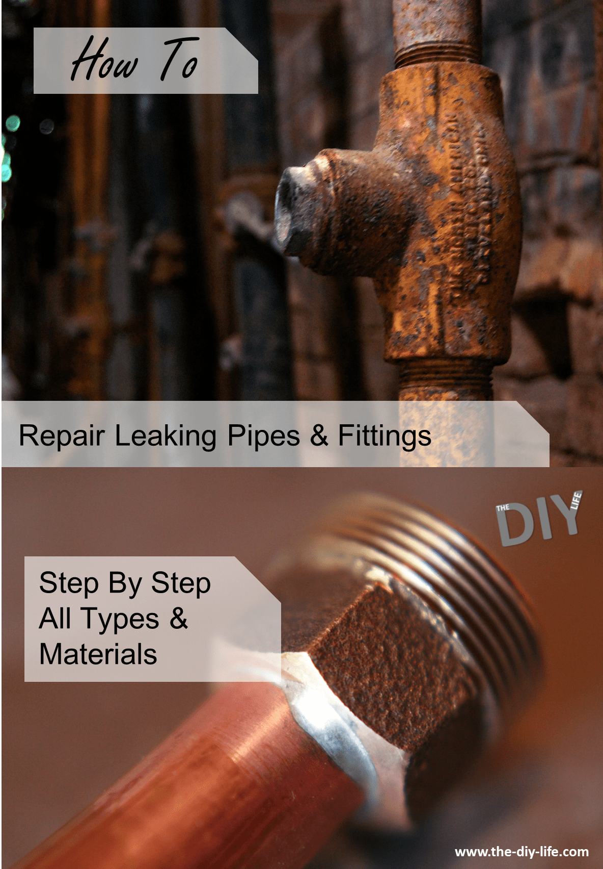
Household plumbing pipes are installed in the walls and underneath the floor during construction. They carry fresh and waste water to and from the kitchen, bathrooms, utility rooms and around the outside of the house for use in the garden. Occasionally, a pipe in your home may start leaking and will require a repair, as long as you can turn the water off and it is not underground, you should be able to fix it yourself without having to call in an expensive plumber.
Pipes typically come in PVC plastic, copper, cast iron, galvanised steel and brass with fittings made out of the same materials to connect them all together as well as to the drains and taps or faucets. Pipes don’t typically move although they do experience vibrations from turning appliances or taps/faucets on and off. They usually start leaking due to age or corrosion and can sometimes be damaged by freezing water.
First Locate The Leaking or Damaged Pipe
If your plumbing has started leaking, you will need to trace the leak back to the problem area in the pipe. Water tends to flow well, especially through gaps and slits in the walls and brickwork so tracing the leak may be a bit tricky. Water leaking out of a wall in one area may not be coming from the section of pipe directly behind it, the water may have flowed down the pipe or wall some way from the original leak. Keep this in mind when trying to locate the leak.
If the leak is in a bathroom behind tiles or in an expensive area of your home and your are not completely sure where the actual pipe damage is, it may be worth your while to call in a plumber as they have the experience and tools to more specifically locate the problem area and make a less conspicuous entry.
How To Repair The Leaking Pipe
The repair you need to make to the pipe depends on what part of the pipe is damaged and leaking and what material the pipe is made from. Here are some of the more common failures and how to fix them.
Make sure that the water supply to the pipe is turned off before attempting to cut into or remove any sections of pipe or fittings.
Replace A Copper Pipe Fitting
Clean the inside of the pipe fitting with a wire brush or emery paper so that it shines.
Clean the outside of the copper pipe in the same way until it shines as well.
Apply a thin coat of solder flux onto the inside of the fitting and the outside of the pipe on the shiny areas.
Insert the pipe into the fitting so that it is correctly seated and turn it to spread the flux, wipe off any additional flux.
Use a propane torch to heat up the joint until it is hot enough to melt the solder. Push the solder wire in around the entire perimeter of the joint.
Wipe off any excess solder.
Replace A Copper Compression Fitting
Loosen the existing fitting by loosening the nut and pulling out the compression ring.
Remove the fitting.
Slide the new nut and compression ring onto the pipe.
Insert the pipe into the fitting.
Slide the compression ring into place and secure the nut with a pipe wrench.
Remove A Section Of Copper Pipe
Slide a pipe cutter onto the copper pipe.
Tighten the cutting wheel until it gently scores the surface of the pipe.
Rotate the pipe cutter around the pipe once and then tighten the pipe cutter slightly.
Repeat until the pipe has been cut through.
Do this again on the other end of the section to be removed.
Remove the cut out section of pipe.
Patch A Rigid Copper Pipe Section With Plastic Pipe
Once you have cut out the damaged section as outlined above, measure the gap between the pipe ends.
Cut a piece of plastic pipe to suite the gap between the copper pipe and make allowance for the new fittings.
Solder the copper section of the transition fitting onto the copper pipe ends on both sides as outlined above.
Screw the brass and plastic sections of the fitting onto the soldered on fitting.
Check that the plastic pipe is correctly sized by dry fitting it.
Use PVC cement on both sides of the plastic pipe and on the joints. Slide the pipe into the two joints to bridge the gap.
Allow the cement to cure for a few hours as directed.
Replace A PVC Pipe Fitting
Cut the old pipe fitting out with a hacksaw.
Lightly sand the end of the pipe to remove the burrs.
Apply PVC cement to the inside of the new PVC fitting and onto the outside of the pipe.
Slide the pipe fitting all the way onto the pipe, twist it around as you insert it so that the cement is spread out evenly all around the joint.
Remove any excess cement and allow the joint to cure for a few hours as directed.
Replace A Threaded Iron or Steel Pipe
Cut through the damaged pipe with a hacksaw.
Unscrew the two cut off sections from the fittings on each end.
Replace the old pipe with two new nipples with a centre union.
Apply PTFE plumbing tape to the pipe nipples on both ends.
Screw one nipple into the fitting and tighten it with a wrench.
Slide the ring nut onto the installed nipple and then screw the hubbed nut onto the nipple.
Screw the threaded nut onto the second nipple and screw the second nipple into the second fitting.
Tighten the nipples and the threaded nut.
Slide the ring nut onto the centre of the union and screw it on.
Have we missed anything? Let us know in the comments section below and we will add them onto the list.
There’s not much worse than getting to your car, ready to go home only to find that you left something on and your battery has died. If this is the case, hopefully you or someone around you has a set of jumper cables stored in their car. Its fairly easy to jump start a car using a set of jumper cables and someone else’s car with a charged battery, just follow these steps.
What You’ll Need To Jump Start Your Car
Jumper Cables
Someone Else’s Car (With A Charged Battery)
How To Jump Start Your Car
Warning: If yours or the other persons car has an electronic ignition system or is a hybrid or electric vehicle, jump starting may damage it.
Just follow these steps:
Park the donor car in such a way that their battery is as close as possible to your battery. Engage both cars parking brakes and put them into neutral or park.
Attach one red jumper cable clamp onto the positive terminal (+) of your battery. It is also the slightly bigger terminal, if you are having a hard time identifying it.
Attach the opposite red clamp onto the positive terminal of the donor cars battery.
Now attached one of the black clamps onto the negative (-) terminal of the donor car’s battery.
Lastly, attach the other black clamp onto some exposed metal surface on your own car. The metal must not be painted, a mount in the engine bay or the hood hinge, a bolt etc.
Start the engine of the donor vehicle.
Start your own vehicle. If your vehicle doesn’t start, check the clamp connections.
Remove the clamps in the opposite order, start with step 5 and work towards step 2.
Keep your engine running for the next fifteen to twenty minutes to charge up the battery again before turning it off. If you turn off your car and it won’t start again shortly afterwards then the battery is likely damaged. You can try refurbishing your car battery yourself or replacing it with a new one.
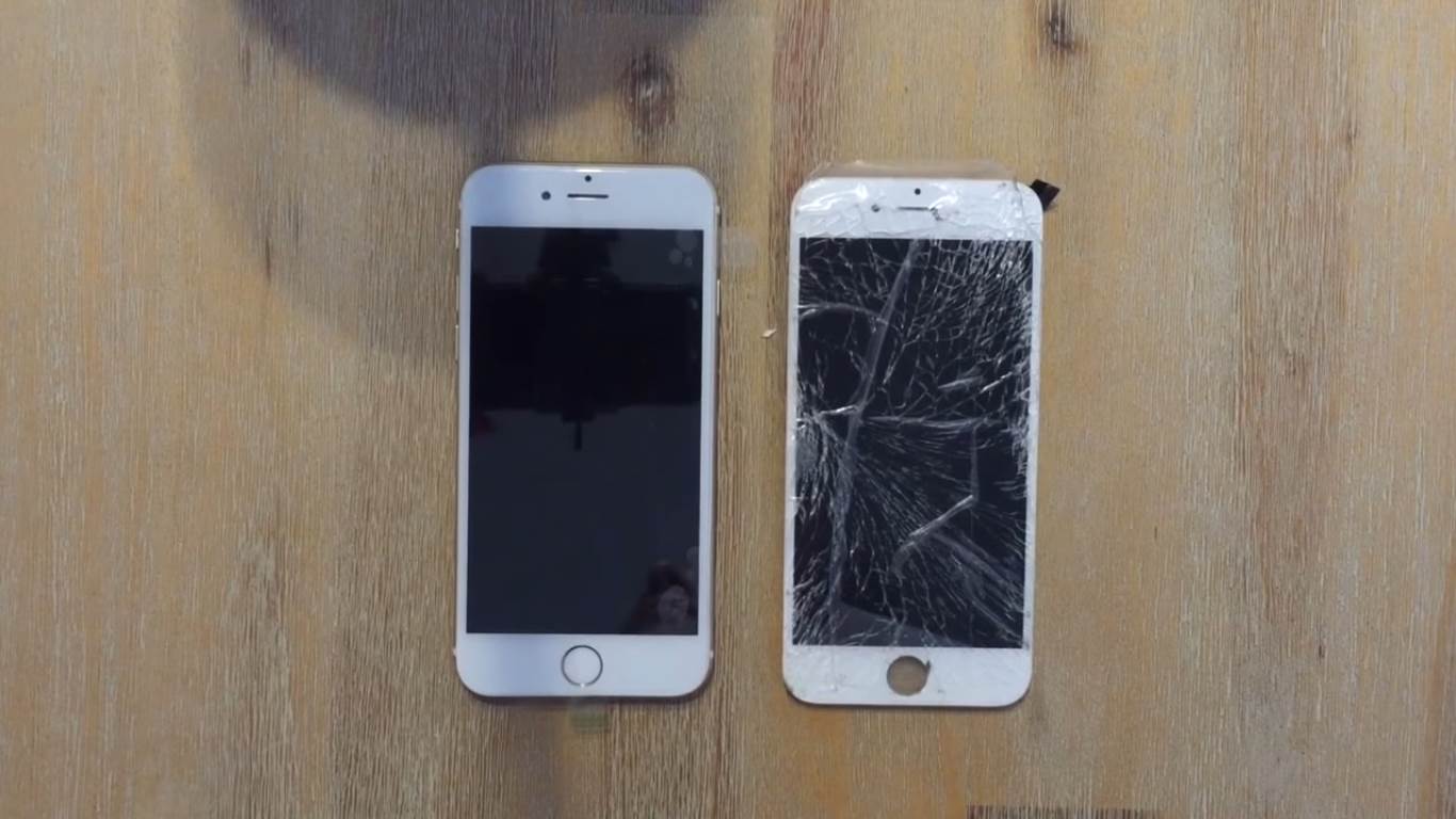
Almost every smartphone owner has at some stage dropped one of their phones and broken the screen. A replacement by the manufacturer costs a fortune but it is actually quite simple to replace yourself. You can buy a replacement for your phone through a number of online stores, eBay has a large number of electronics suppliers which stock replacement parts.
This guide shows you the step by step process to replace your iPhone screen yourself. Although this change is performed on an iPhone 6, the 6s is almost exactly the same.
Scroll down to the bottom of the page for a full video of the change being done on an iPhone 6.
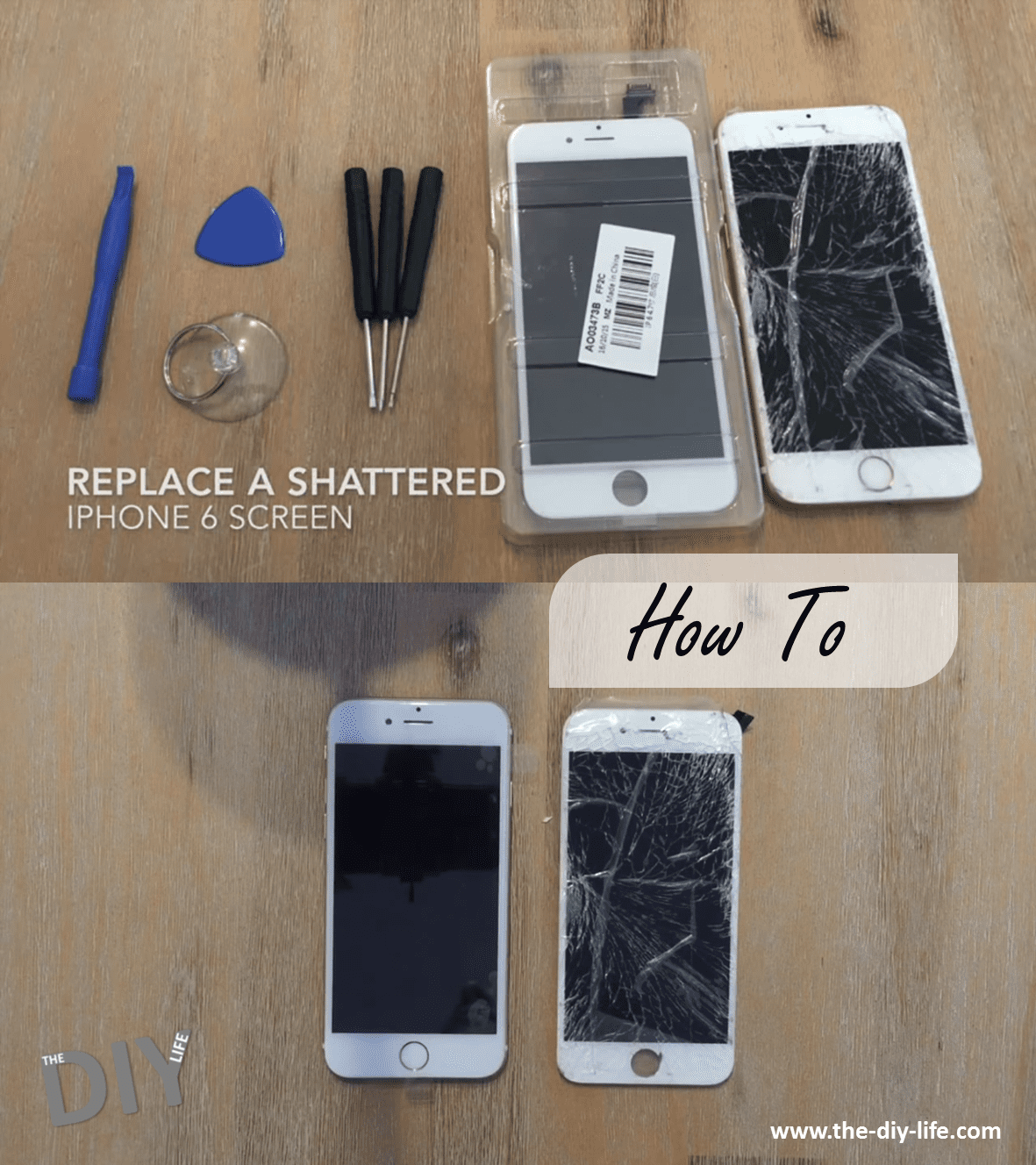
What You Will Need To Replace Your iPhone 6 Screen
If you look around online, most of the suppliers which stock replacements will add a small toolset (pictured in the video and cover picture) for a small fee or even for free, it is worthwhile getting the toolkit.
How to Replace your iPhone Screen
Replacing your iPhone screen is done in four stages, first you will remove the old one, then remove all of the components from the old one, install them on the replacement screen and finally install and connect the replacement to your iPhone.
It is worthwhile keeping a piece of paper and a pen handy to make a sketch of the inside of the phone and which screws your have removed from where. The screws are all different sizes and lengths and need to go back into the same hole you removed them from. Rather spend a bit more time taking the phone apart and keep track of the components, it will make your life a lot easier when putting it back together.
Removing the Broken Screen
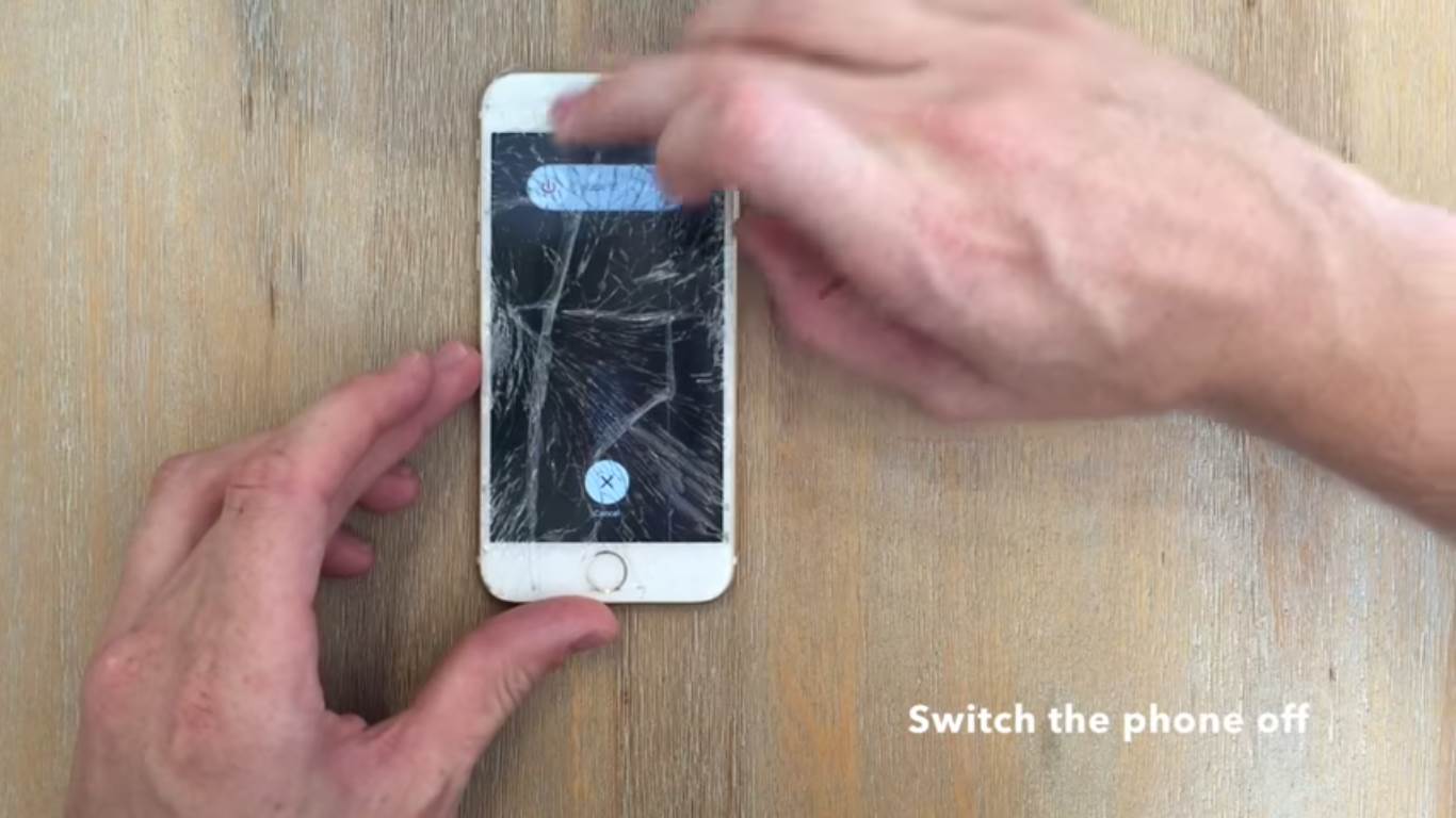
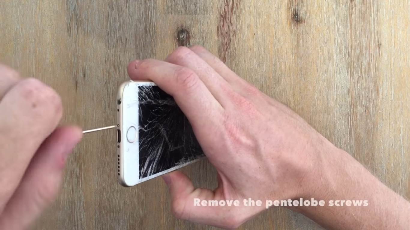
First start by switching your iPhone off, this ensures that you don’t short circuit anything when clipping and unclipping connectors.
Now use the pentelobe screwdriver in your toolkit to remove the two screws at the bottom of you phone.
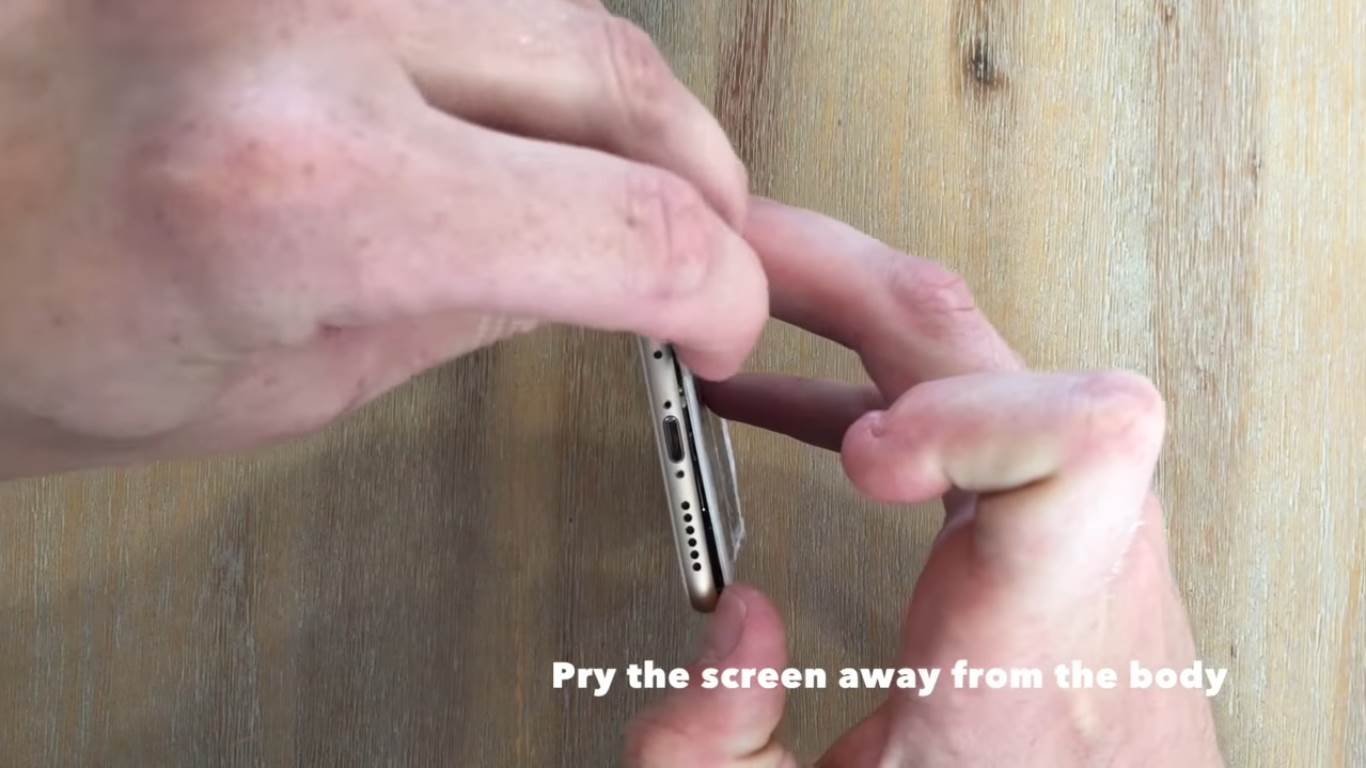
Once the screws have been removed, pry the screen away from the body. If it is not totally shattered, using the pulling suction cup to help you lift the screen from the body of the phone. The prying tool helps to slot in between the screen and the body and pull it away.
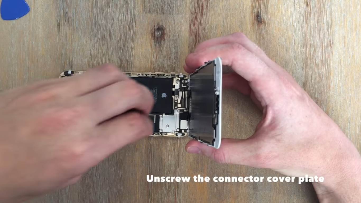
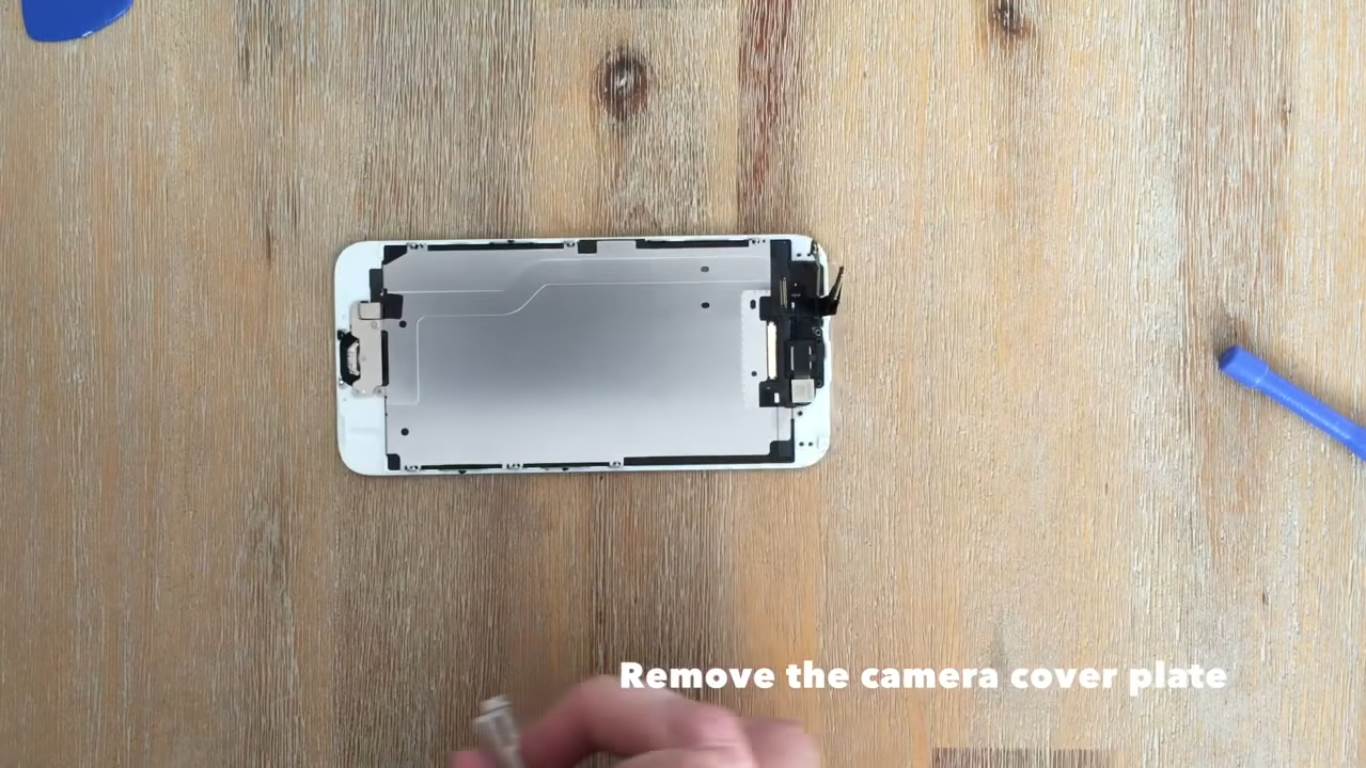
Near the top of the phone, there is a silver cover plate which keeps the connectors locked in place. Unscrew and remove the screws and the cover plate.
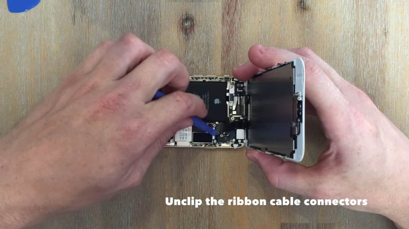
Now use the smaller prying tool to unclip the four connectors on the ribbon cables. These connectors snap into place much like Lego’s. Once the ribbon cable connectors are unclipped, you can remove the screen from the body of the phone.
Remove the Components from the Old Screen
The replacement you have bought will most likely come without any of the additional electronic components mounted onto it, you will have to move these across from your old screen onto your new screen.
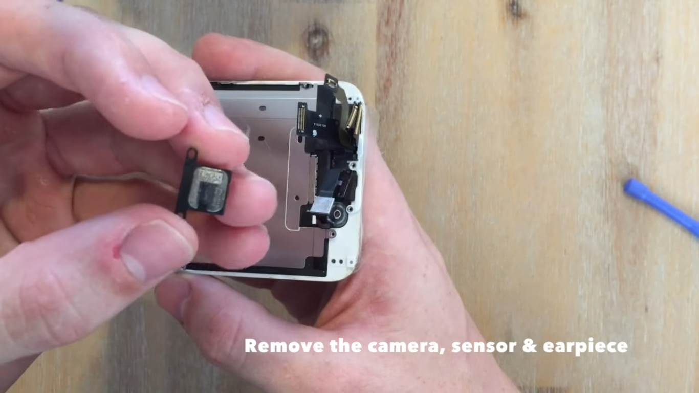
First start by removing the camera, sensor and earpiece. Remove the screws and cover plate which secure the camera.
Now remove the camera, sensor and ear piece, they should come away easily with the cover plate removed.
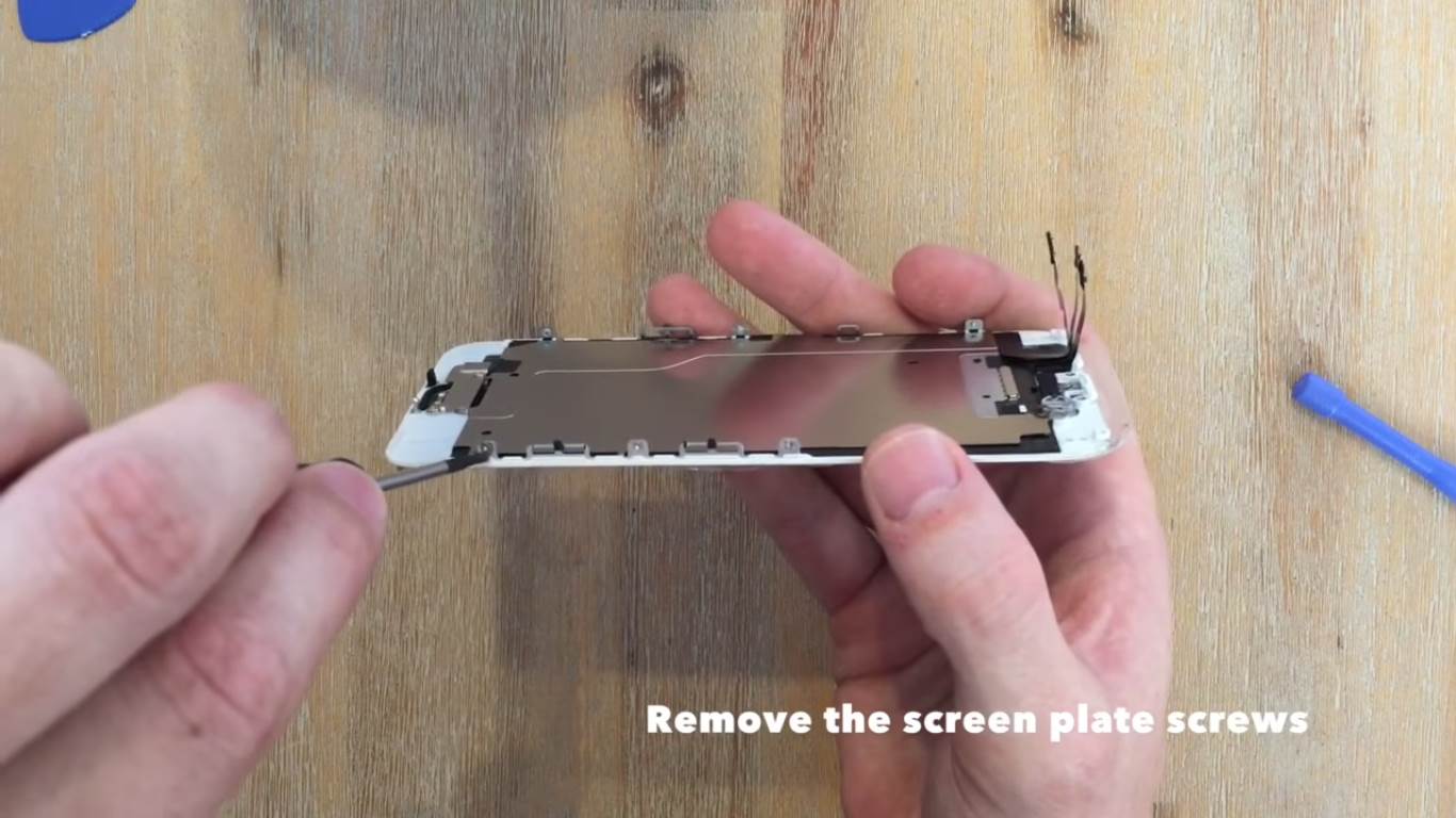
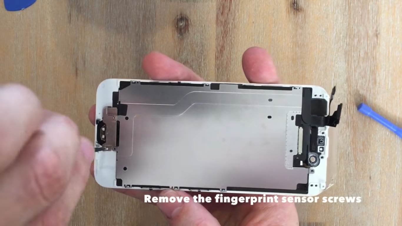
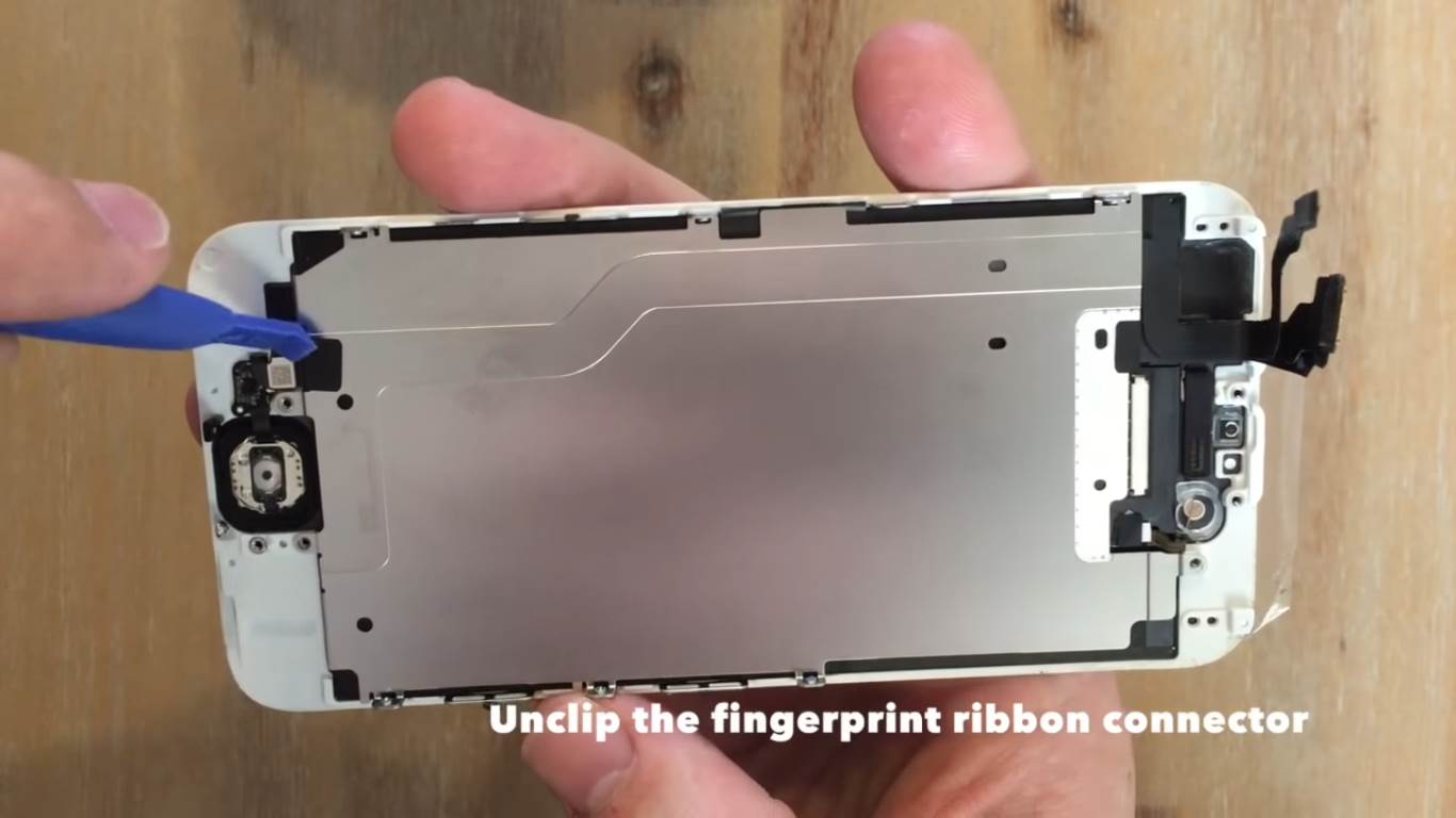
You need to remove the screws to the silver cover plate on the back, this houses the ribbon cable to the fingerprint sensor and home button. Remove the screws around the perimeter of this cover, the cover will remain in place until the fingerprint sensor is removed.
Next, remove the cover plate over the fingerprint sensor.
Unclip the connector to the fingerprint sensor ribbon cable, this is the same type of connector used to clip the other ribbon cables and it just snaps off using the prying tool.
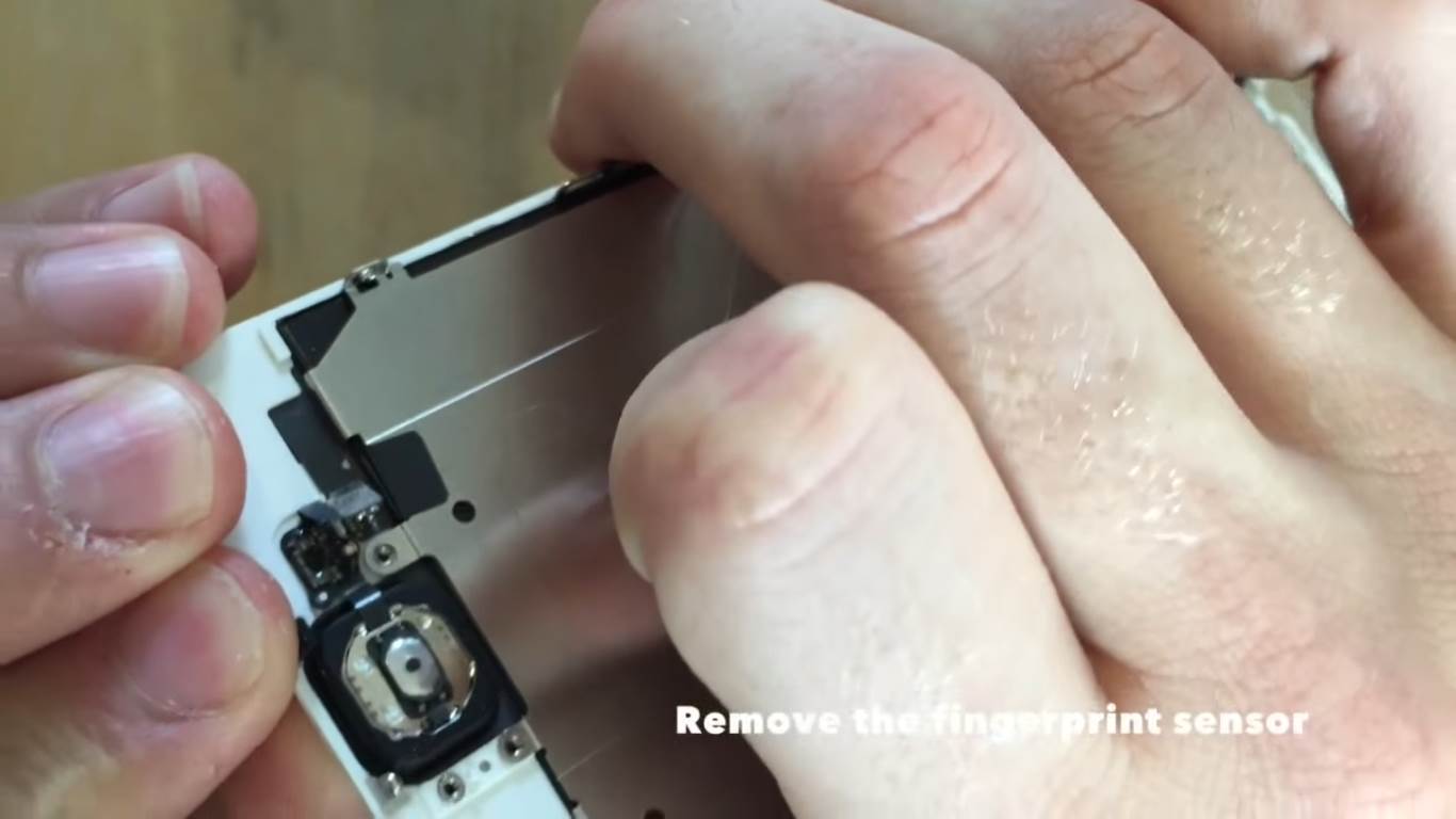
Now you can remove the fingerprint sensor. It is stuck on by its rubber mounting which is sticky on one side. Simply pull it off with your fingers or with a flat screw driver. It should still be sticky enough to stick onto the replacement.
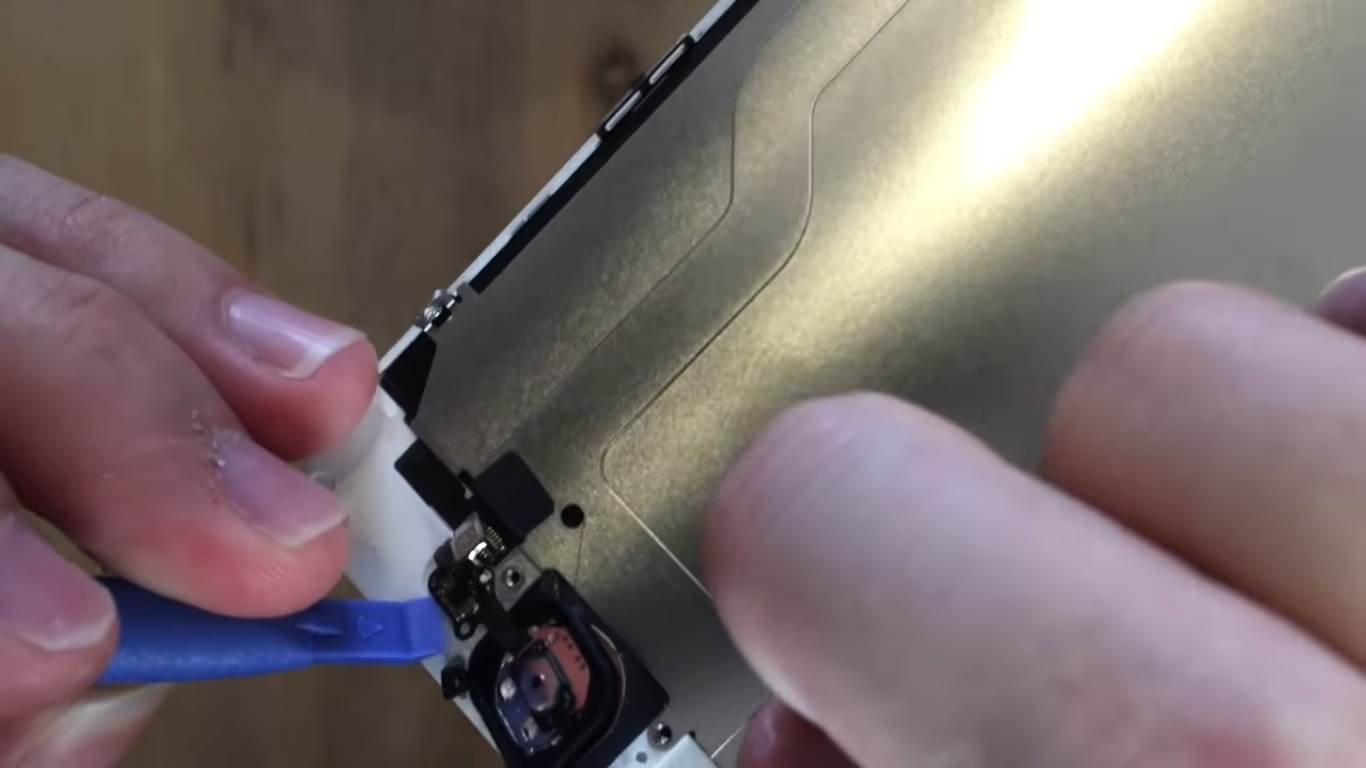
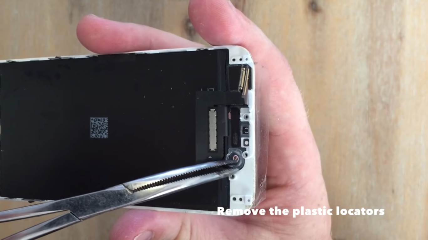
Lastly, unclip the fingerprint sensors electronics which are held in place with a small white peg. Use the prying tool to lift it off of the peg.
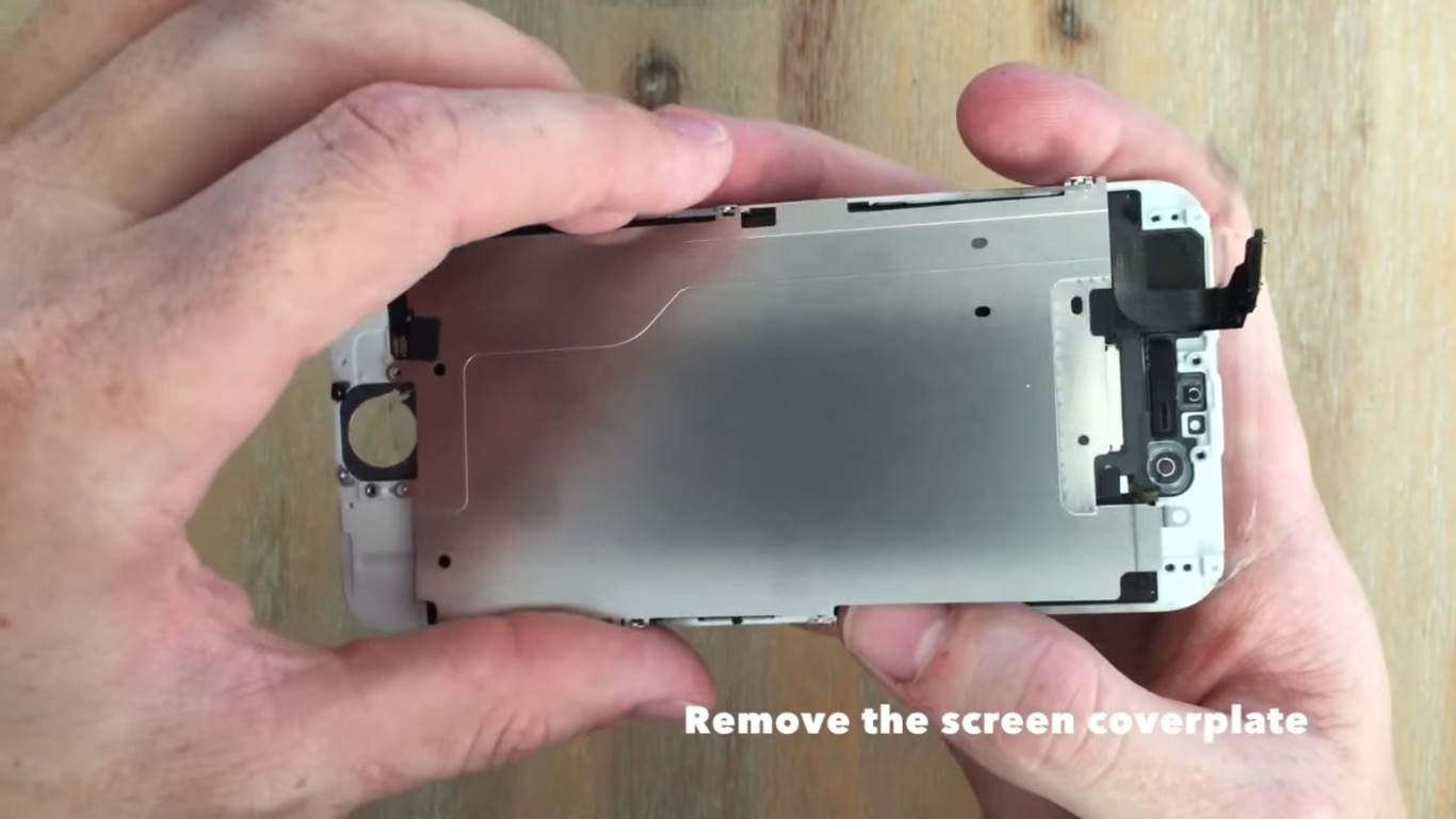
Now you can remove the back cover plate.
The last items to remove are the small plastic locators for the camera and for the sensor near the earpiece. Remove these with a tweezer or small screwdriver.
Install the Components on the New Screen
Installing the components on the replacement is quite easy once you know how they came off the old one, just follow the steps in reverse.
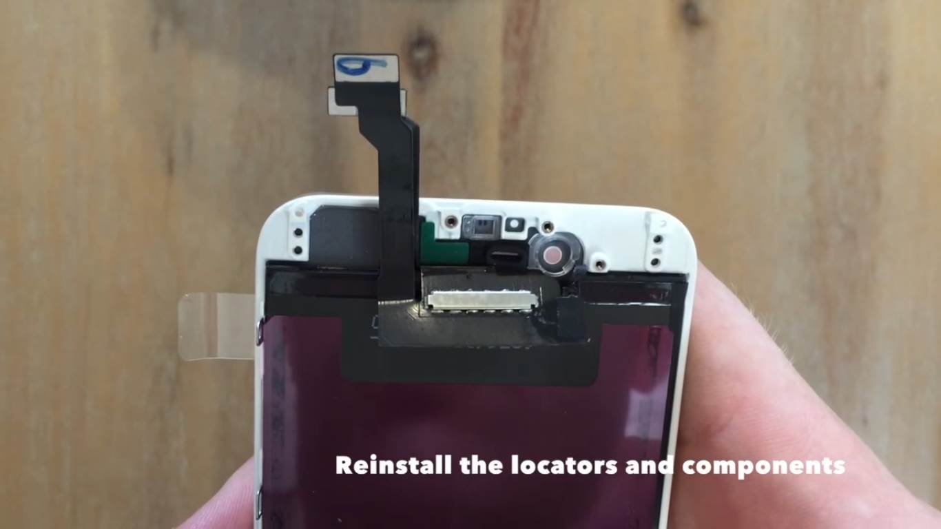
First replace the plastic locators for the camera and sensor.
Now replace the camera and sensor. The small white pegs act as a location guide and the components fit into the plastic locators.
Replace the earpiece and then screw the silver cover plate back into place.
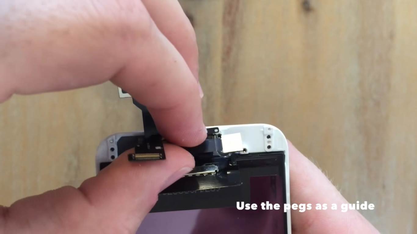
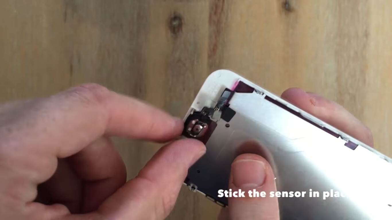
Next, stick the fingerprint sensor onto the replacement with the sticky side of the rubber mounting. Clip the electronics in place over the white plastic peg.
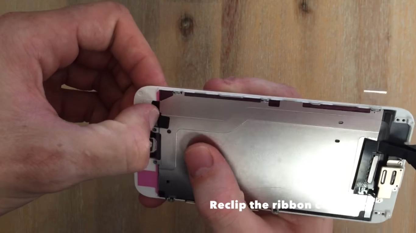
Clip the ribbon cable connector in.
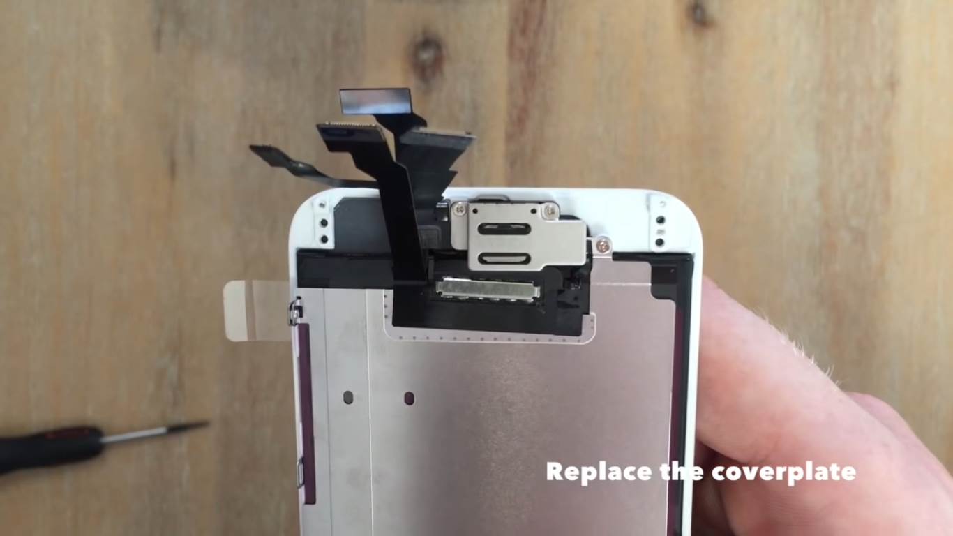
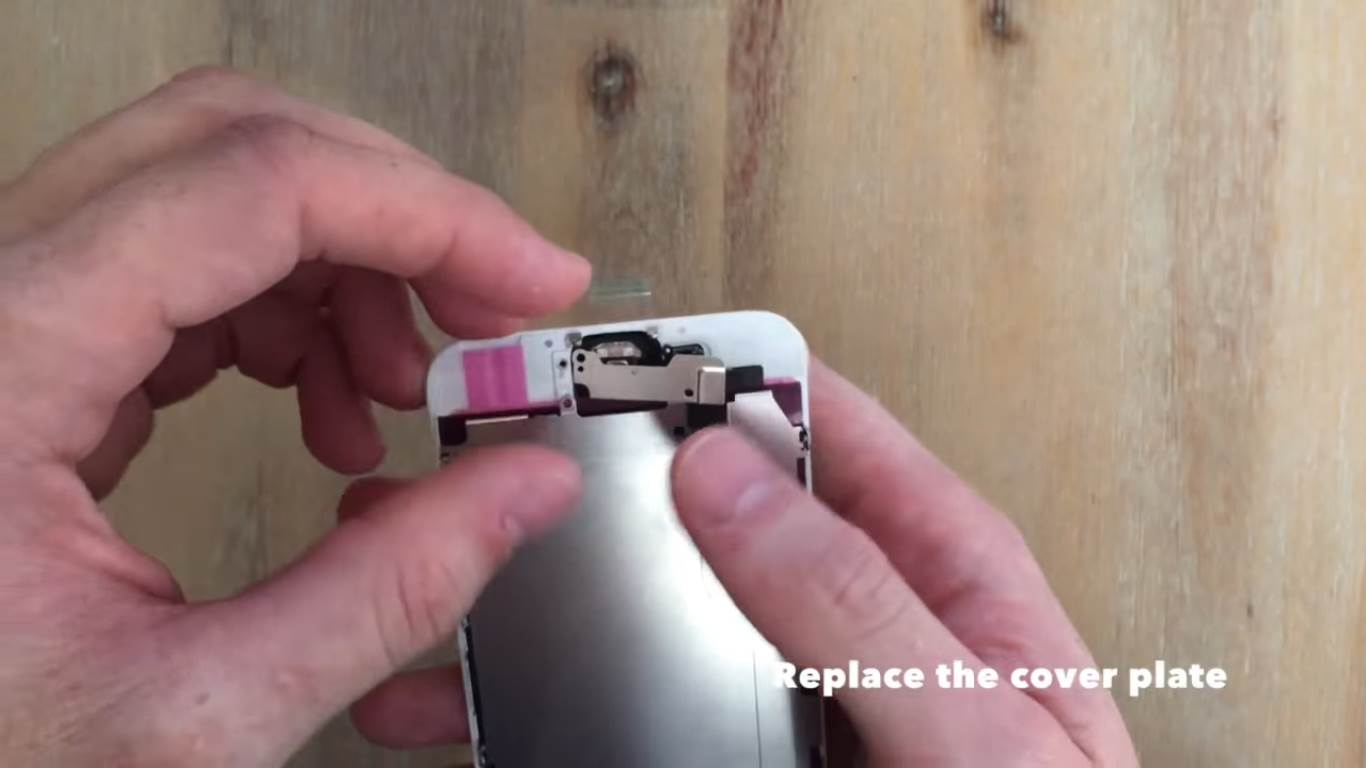
Now replace the fingerprint sensor cover plate and screw in the screws.
Replace the cover plate and screw in the screws around the perimeter.
The replacement is now ready to be reinstalled on the body of the phone.
Install The New Screen
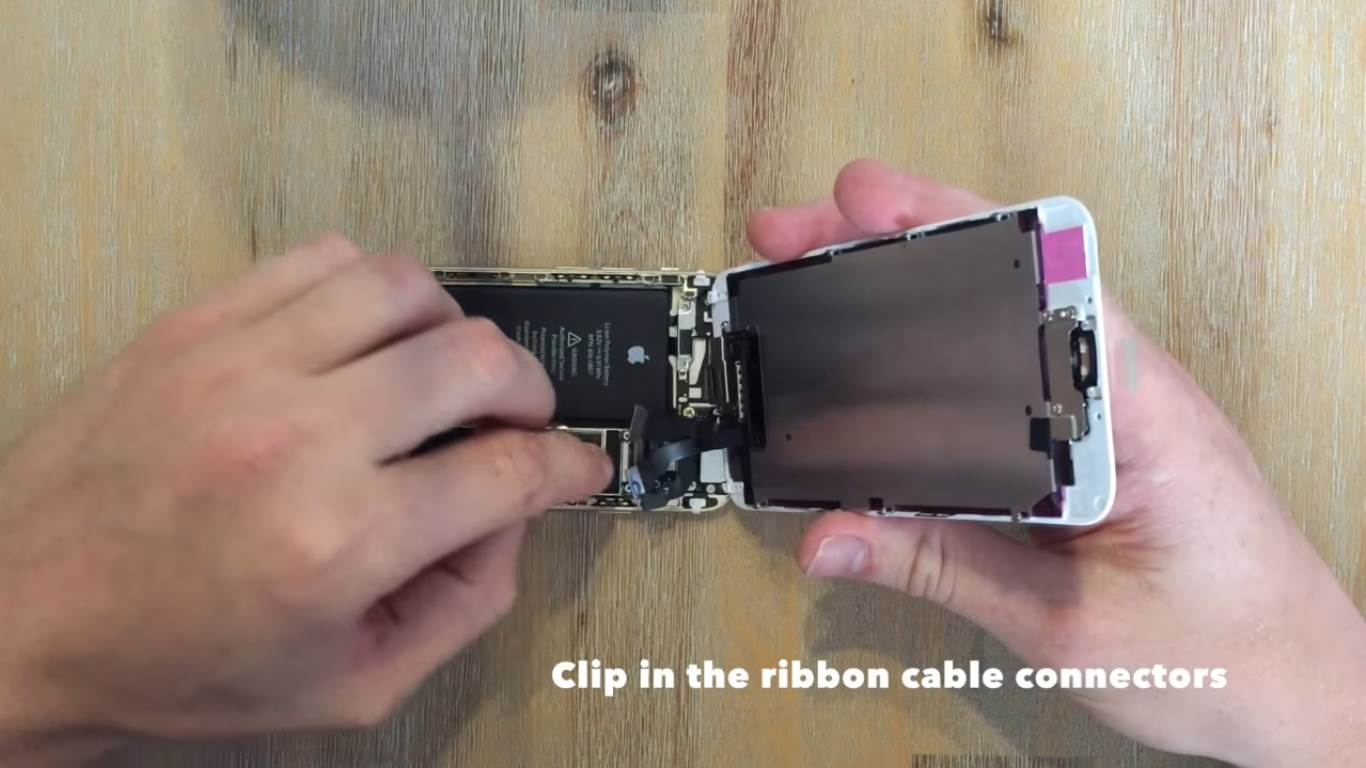
Start installing the new screen by clipping in the four ribbon connectors. Each one is a different size and shape so it should be easy to see which one goes where.
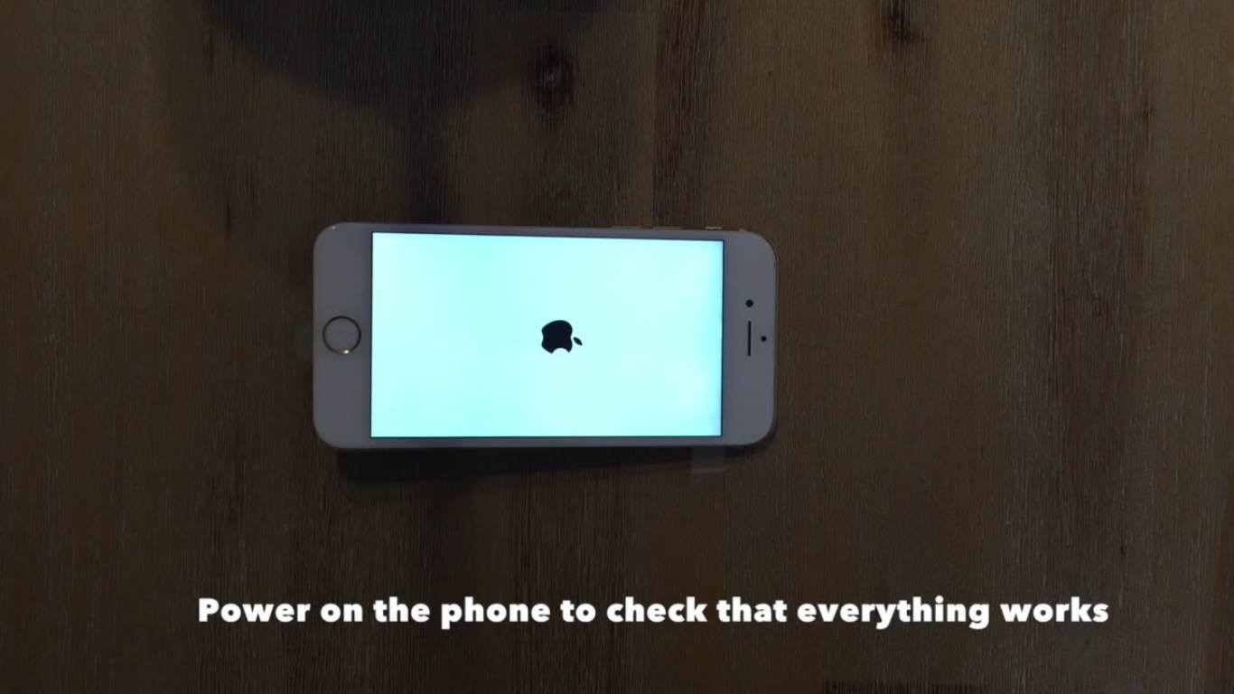
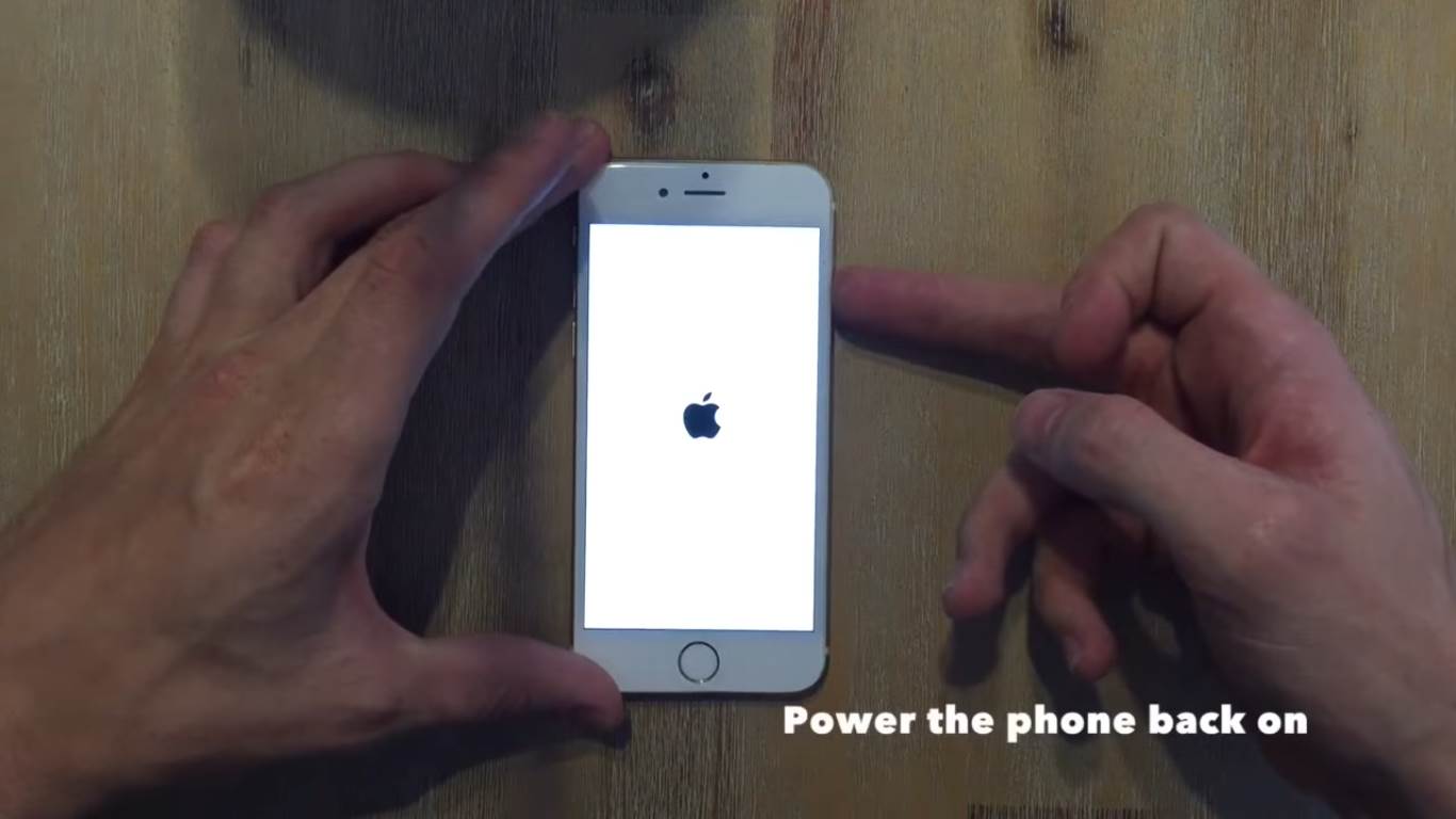
Fold the screen down gently and rest it on top of the body. Now you should check that everything which you have connected is working correctly. Power on the phone and make sure that it displays correctly, the touch sensor works, the fingerprint sensor and home button work as well as the front camera alignment. If anything doesn’t work then it is likely due to a fault in the ribbon cable connections, try unclipping and reconnecting them.
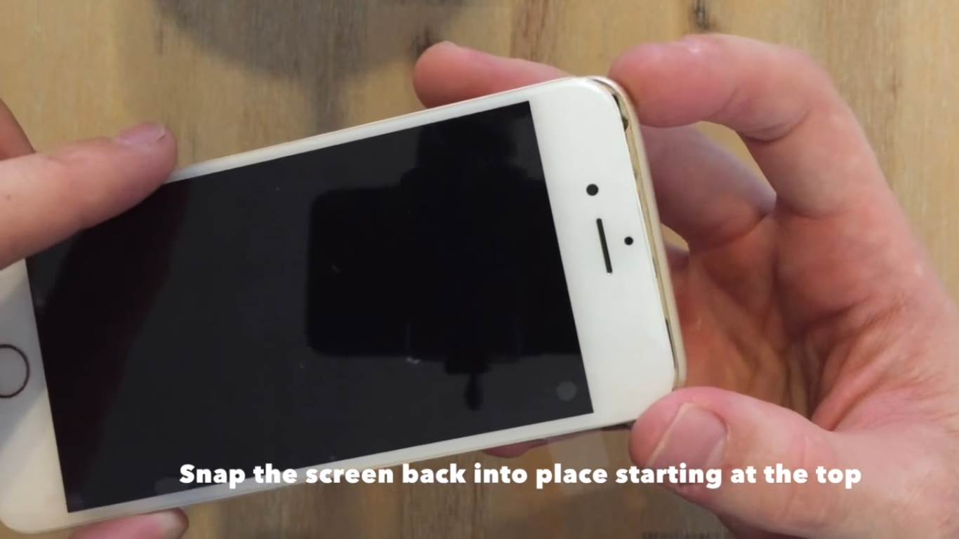
Once everything works, turn the phone off again and then begin securing the screen. At the top are two plastic clips which slide into the body of the phone. It can then be pressed into place from the top down.
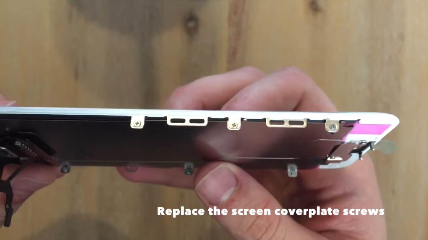
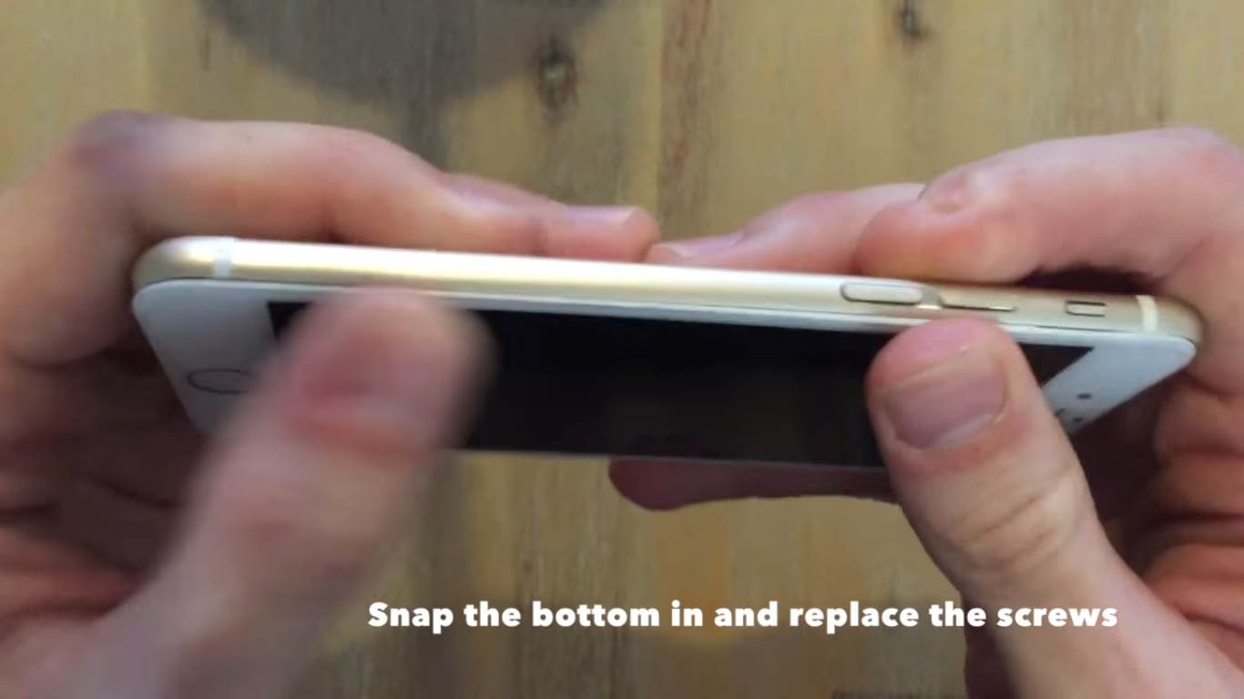
Snap the bottom into place and align the screw holes. Finally slide the pentelobe screws in and screw them in.
You have now successfully replaced your phone screen!
Power the phone back on and it is ready to use again.
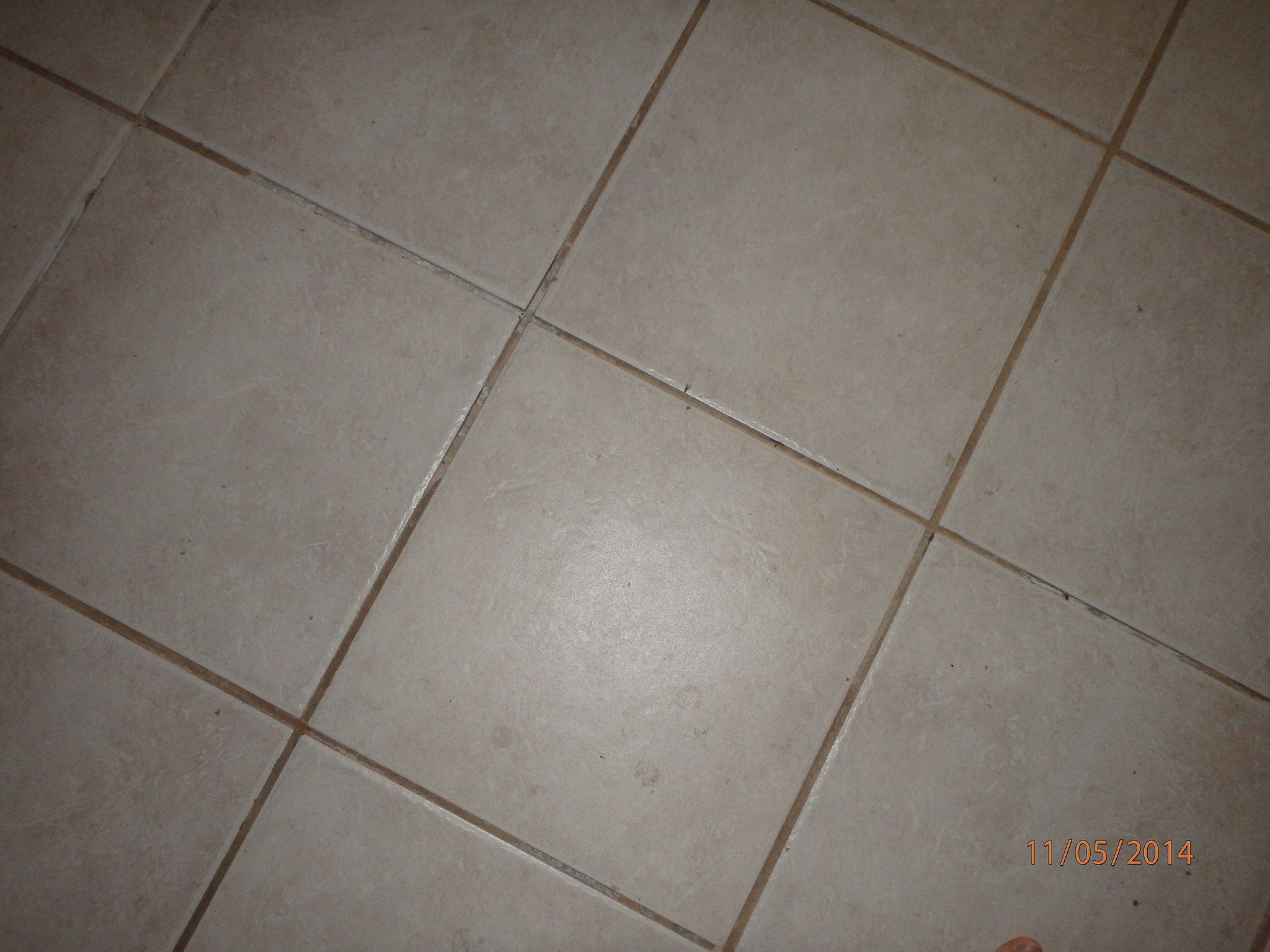
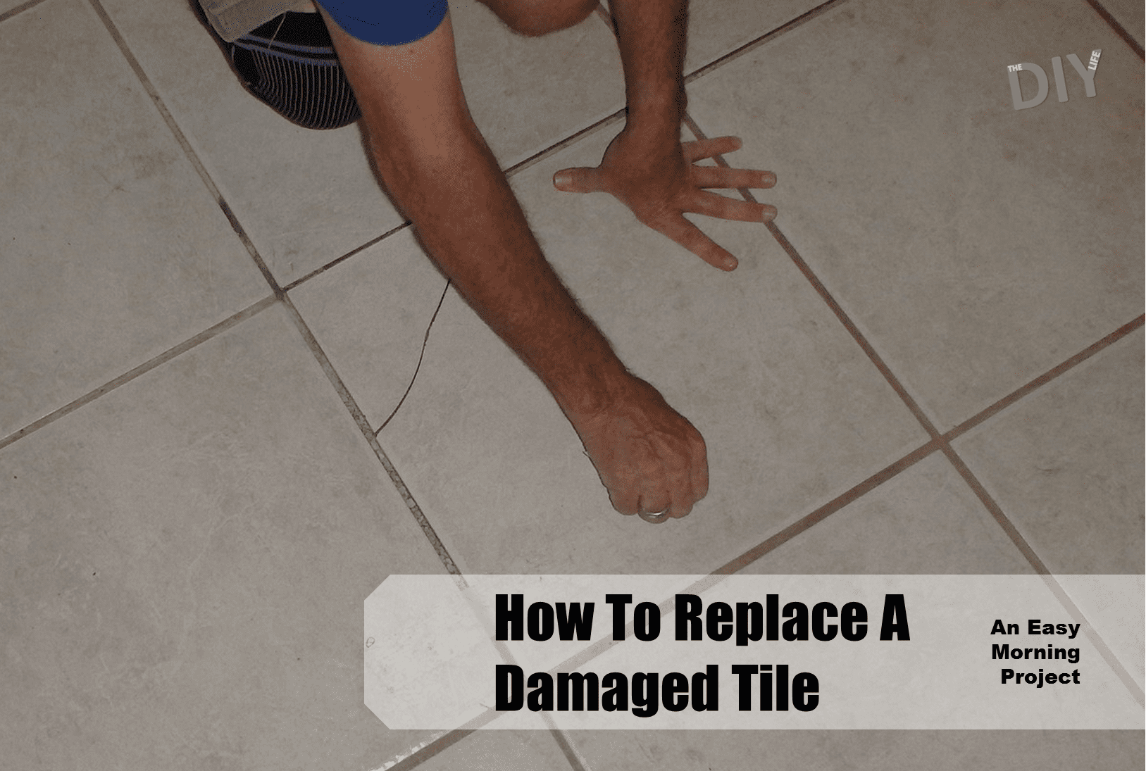
With the natural movement of foundations, environmental changes and general wear and tear, eventually one or two tiles on your walls or floors may land up cracking. You may also have removed a fixture or fitting which has left holes or a portion of the tile removed. Fortunately, its relatively easy to replace the cracked or modified tiles and it can easily be done in a morning.
If your tiles are particularly bad but you can’t face pulling them up, why not try tiling over the existing tiles? As long as your existing still are still well bedded, they make a perfect base for tiling over.
What You Will Need To Replace A Cracked Tile
A Replacement Tile For Each Cracked Tile (These Should Be Kept From The Original Installation)
Grout Removal Tool (Dremel Rotary Tool with Grout Removal Attachment)
Hammer
Chisel
Tile Adhesive
Grout (Same Colour As Used)
How To Replace The Cracked Tile
First you need to remove the existing tile. Start out by removing the grout the whole way around the tile using the dremel rotary tool or a grout saw. This process produces a lot of dust so a breathing mask is required.
Now break up the cracked tile in order to remove it. You will need to break it into small sections which can then be pried up with the chisel. Be careful not to damage one of the surrounding tiles when lifting the broken tile pieces, do not lean the chisel on the surrounding tiles when chipping or lifting.
Warning: Wear adequate eye protection when chipping out the old tile. Shards of the glazing can be extremely sharp.
Remove all of the old adhesive underneath the cracked tile as well, you need a clean and flat bed on which to lay the new tile. A paint scraper may be easier to use to get the last of the adhesive up.
Mix up some tile adhesive and spread it over the entire back of the tile. If you have a notched tile trowel, use this to create adhesive beads/rows for better application. Leave a 6mm (1/4″) perimeter around the tile free of adhesive so that it doesn’t push up and fill the grout joint.
Now press the tile down in place so that it is square and level with the surrounding tiles. Use a straight edge to check that it is level with all four surrounding tiles, tap down lightly with the hammer on any high spots or on the opposite side to lift any low spots.Let the adhesive set as directed on the packing, usually 6 to 12 hours before grouting.
Finally mix up some grouting and grout the joints. Use a grouting sponge or your fingers to apply the grout as it is a small area. Clean up any excess grout and then allow it to set before walking on the repair or letting it get wet (in a bathroom or shower).
The tile may stick out initially because the tile and grouting will be a little cleaner than the surrounding tiles but after a few weeks it won’t be noticeable and will certainly look better than a cracked tile.
When you go out of the house for the weekend or on vacation for a while, you don’t have any way to tell if there was an electricity blackout or how long it lasted. So how do you know if your food in the freezer is still good to eat? The food could have warmed up to room temperature for a day or two without you knowing.
Here is the solution, this simple trick will tell you if your freezer temperature ever reached a stage where the food was able to thaw and is possibly not good to eat anymore.
What You Need:
A Coin
A Cup, Small Container or Ice Tray
Some Water
How To Tell If The Freezer Went Off
All you need to do is put the water into the container, cup or ice tray and wait for the water to freeze. Once the water is frozen, place the coin on top of the water. Leave the coin, cup and ice in the freezer for as long as you need to, all you need to do to check if the power went out for a long period is check on the coin. If the coin is still on top of the frozen water then you know the power has been on and the ice didn’t melt. If the coin has sunk or is frozen in the bottom of the water then you should check all of your food because the power was out for long enough for the ice to melt.
Obviously, the less water in the cup the quicker it will melt so try not to put too much water in the bottom of the cup or container. A typical ice cube is the right sort of volume and putting a coin on one of the cube slots will achieve the same results, just be sure to not use that cube in a drink.
Do you have any vacation tips and tricks? Let us know in the comments section below.