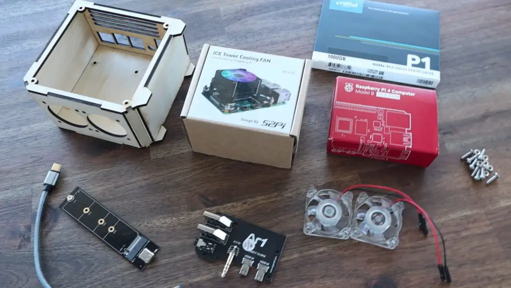
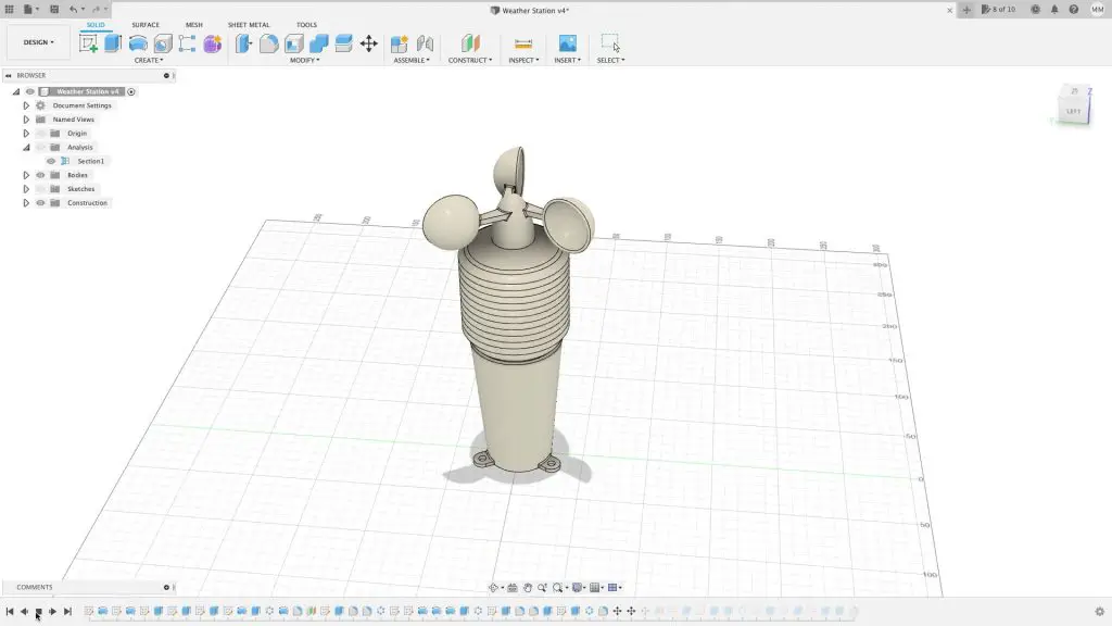
In this project, we’re going to be taking my previous Raspberry Pi Desktop Case design and adapting it to accommodate an SSD underneath the Pi.
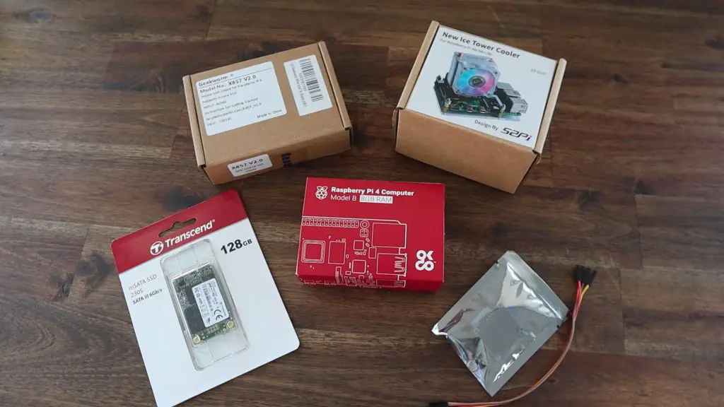
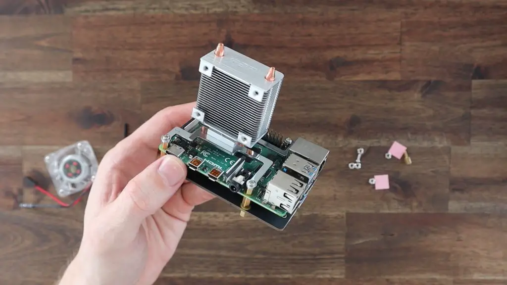
The case uses the same Raspberry Pi and Ice Tower combination that I used on the last version, but this time I’m going to add a Geekworm mSata SSD shield and a 128gb SSD. I’ve chosen an mSata shield and drive as these are typically quite a bit cheaper than NVME drives, and you don’t get that much benefit from using an NVME drive as you’re limited by the maximum speed of the USB 3 port in any case. You only really benefit from an NVME drive if it is connected through a PCIe port.
This case design is also compatible with the Geekworm M.2 NGFF SSD shield.
You can buy a premade kit to assemble your own Pi SSD Case from my Etsy store.
Watch my video of the build below or read on for the full project details:
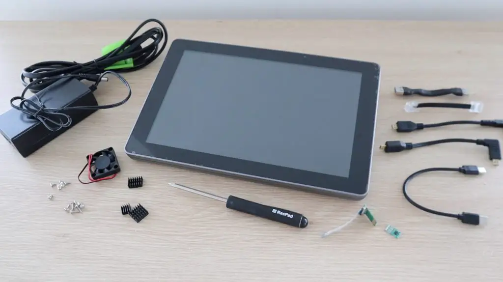
What You Need For This Project
or
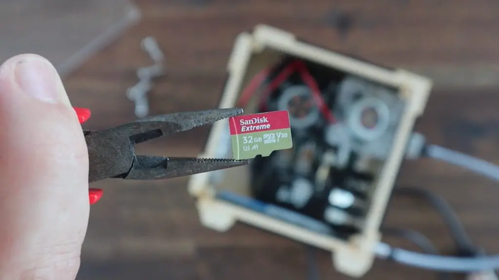
- MicroSD Card (For Setup) – Buy Here
- I2C OLED Display – Buy Here
- 15cm Female to Female Ribbon Cable – Buy Here
- 2mm Clear Acrylic – Buy Here
- 9 x M3x8mm Button Head Screws – Buy Here
- 4 x M3 Nuts – Buy Here
- Optional SSD Heatsink – Buy Here
Equipment Used
- Creality Ender 3 V2 3D Printer – Buy Here
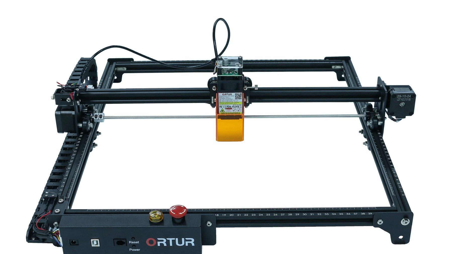
- K40 Laser Cutter – Buy Here
- Electric Screwdriver – Buy Here
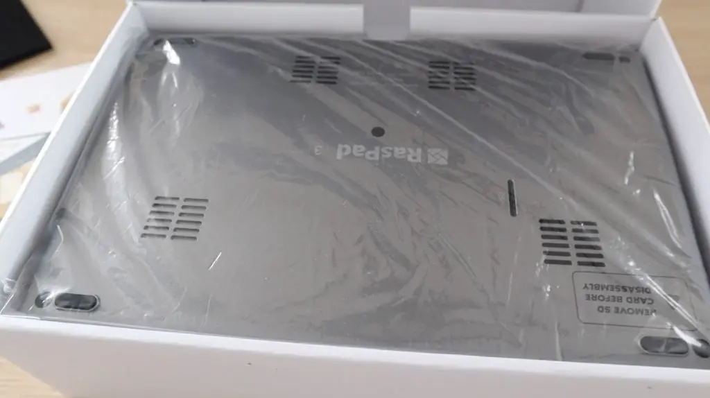
Preparing Your Components
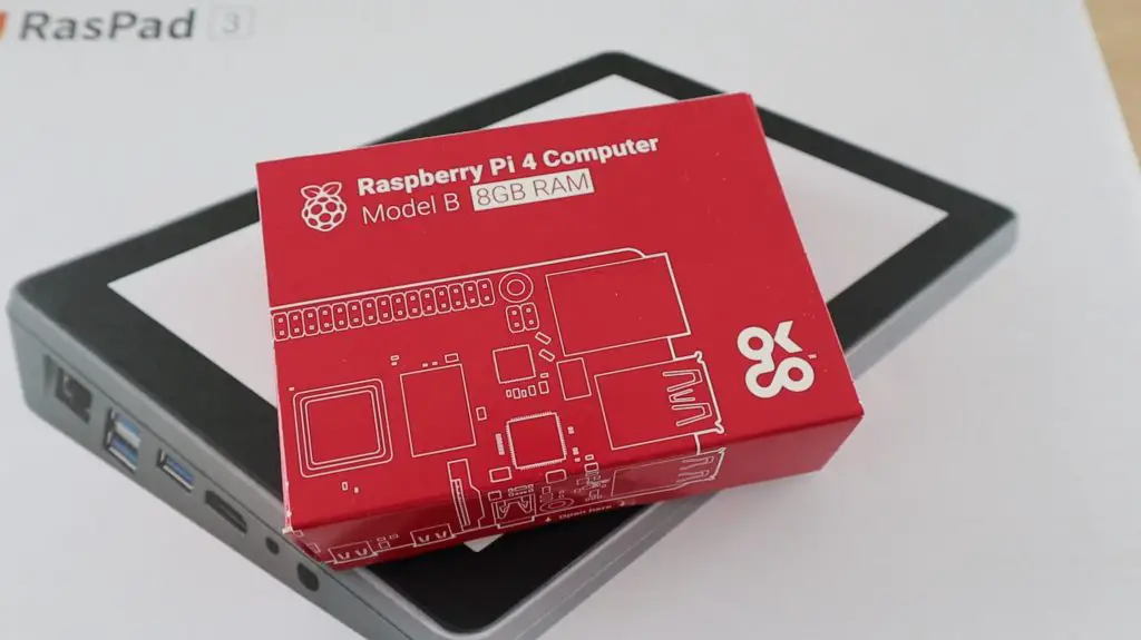
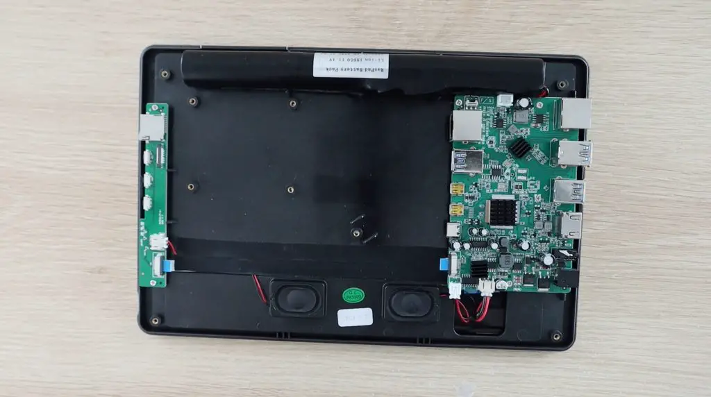
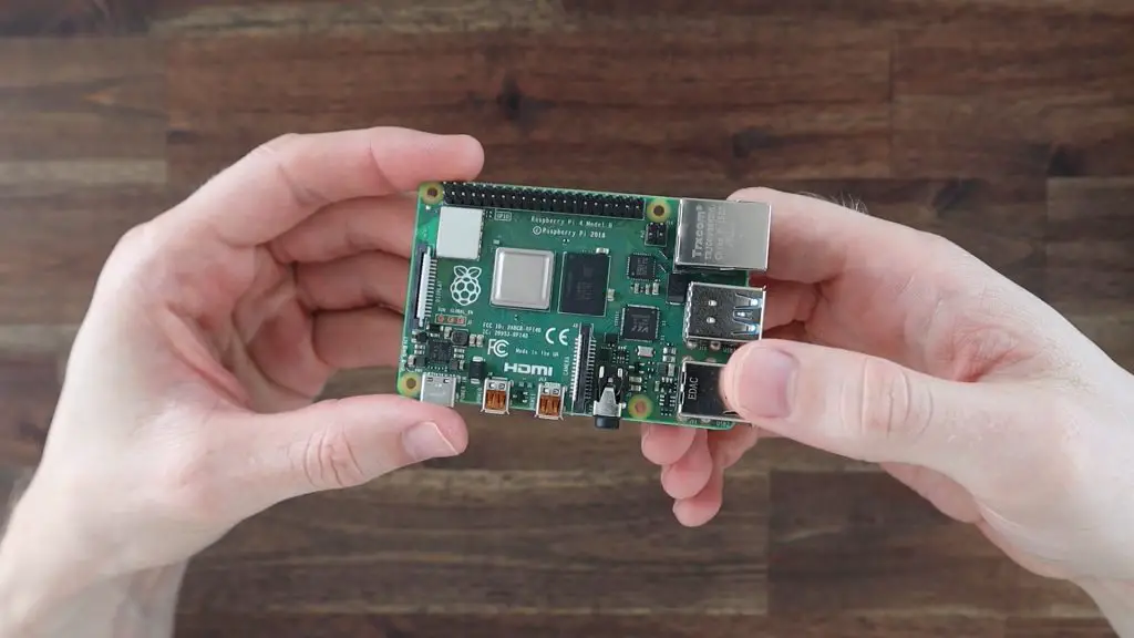
I’m using an 8GB Raspberry Pi 4B, but you can use the 2GB or 4GB version as well as they’re identical in their layout. Unfortunately, this case won’t be compatible with the Pi 3 or 3b+ as their port layouts are different to the Pi 4.
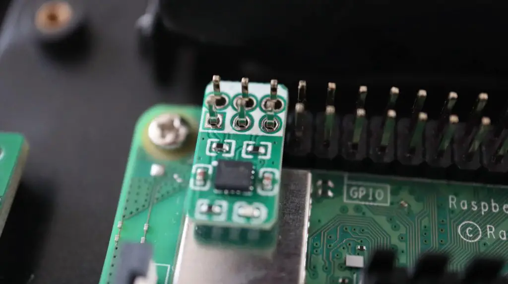
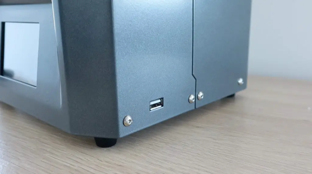
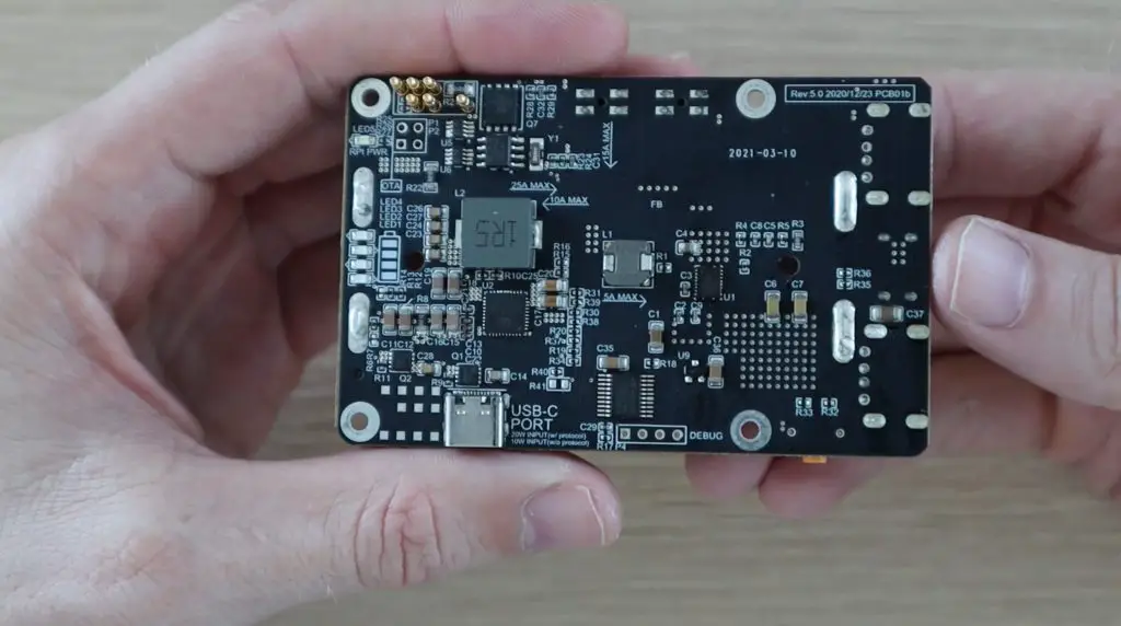
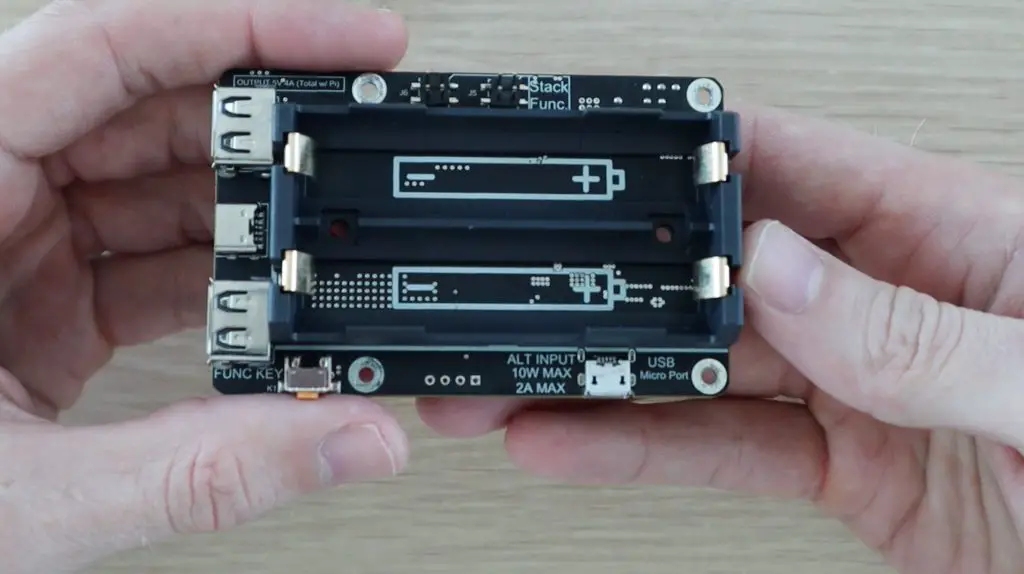
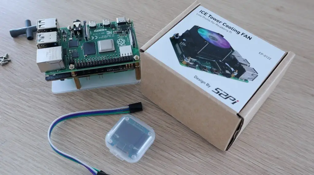
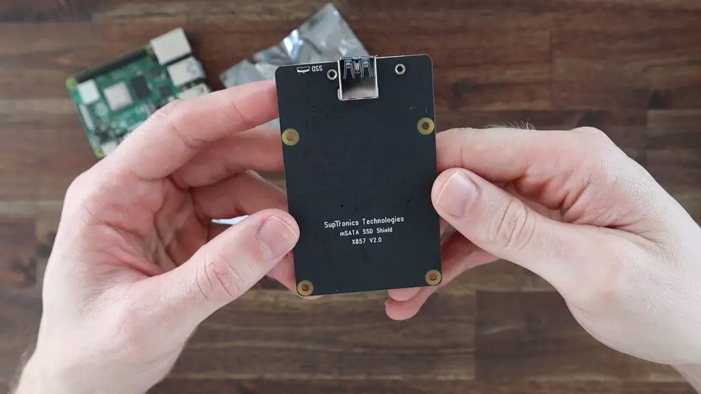
I’m designing this case around the Geekworm mSATA SSD shield. This is version 2 of this shield, so it is powered directly through the USB port and is slightly lower profile than the earlier versions. It supports UASP and up to a 2TB mSATA SSD.
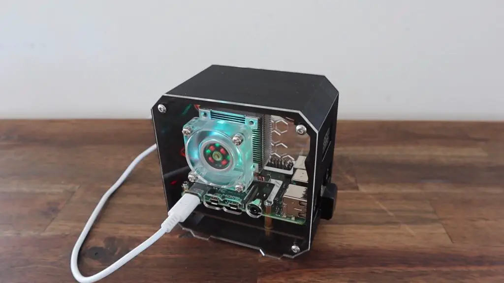
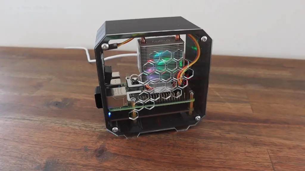
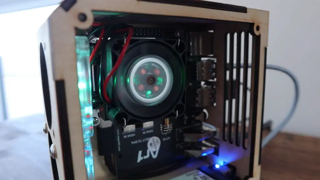
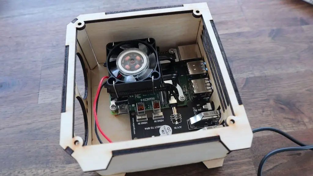
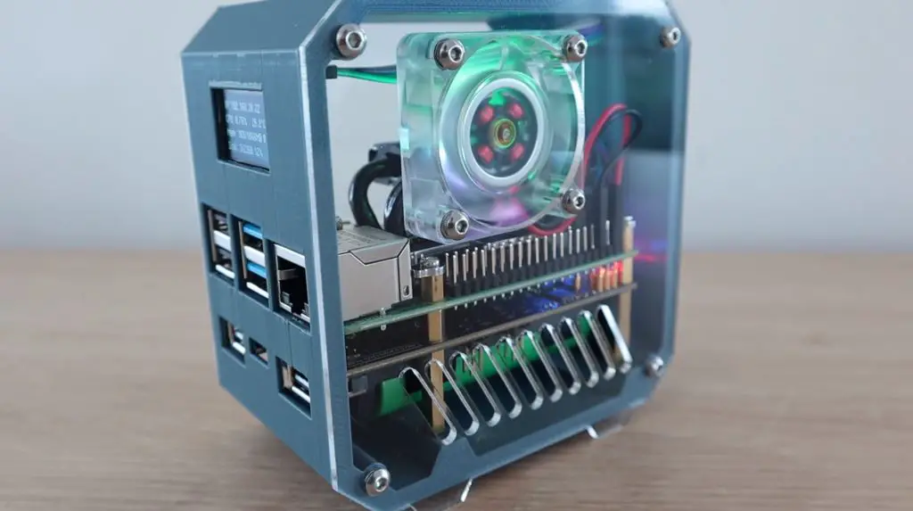
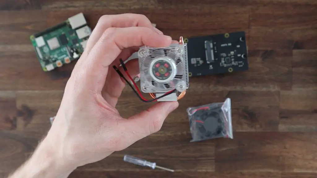
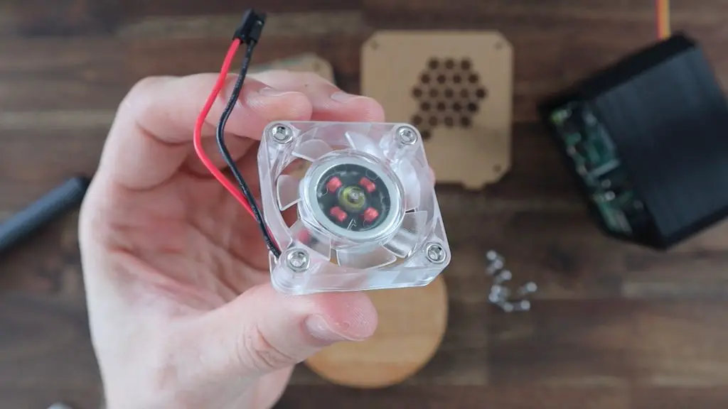
Cooling will be provided by an Ice Tower, which is a large heatsink that sits on top of the CPU. We’re going to move the fan off of this heat sink and onto the side of the case. It’ll be positioned so that it pulls air in from outside the case and blows it across the heat sink and out vents on the opposite side.
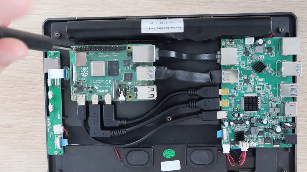
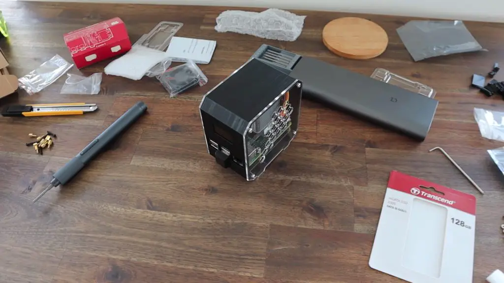
Assembling The Pi & SSD Stack
Let’s start off by assembling the Pi stack so that we can take measurements from it so that we know what we need to modify on the case.
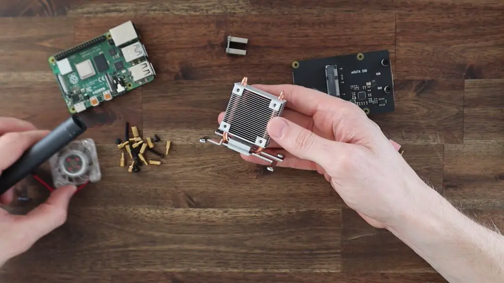
First, we need to mount the legs onto our Ice Tower. These are just installed as per the instructions supplied with the Ice Tower and screw in underneath the heat sink.
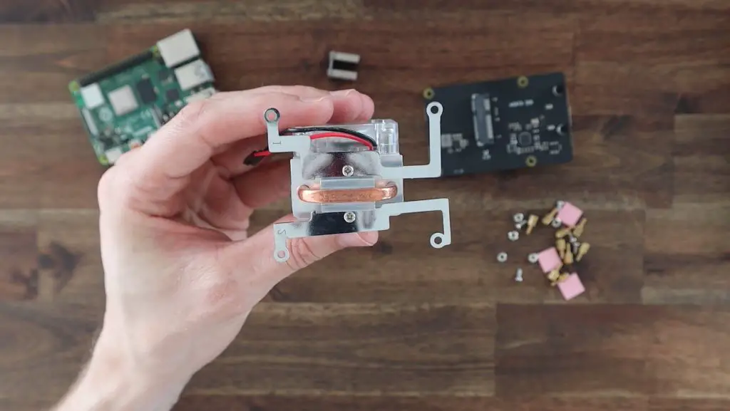
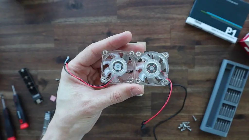
Next, let’s remove the fan from the Ice Tower so that we can mount it on the side of our case later on. Set the screws aside as well as we’re going to re-use them.
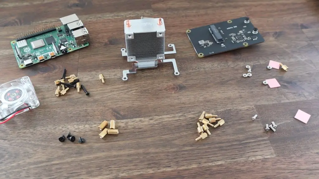
The Ice Tower and the SSD shield both come with some screws and standoffs to mount them onto the Raspberry Pi.
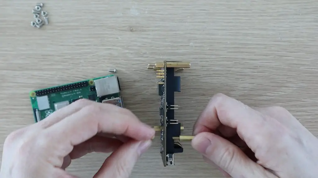
For this case, we’re going to use the 4 female-to-female standoffs and 4 black screws from the SSD shield, leaving the longer screws and male-to-female standoffs unused. We’re also going to use 8 brass standoffs from the Ice Tower and four silver screws to secure it. We won’t be using the four nuts or the spare screw and standoff.
Although the male-to-female brass standoffs that come with the SSD shield might look similar to the Ice Tower ones, they’re actually a bit longer, so don’t muddle them up.
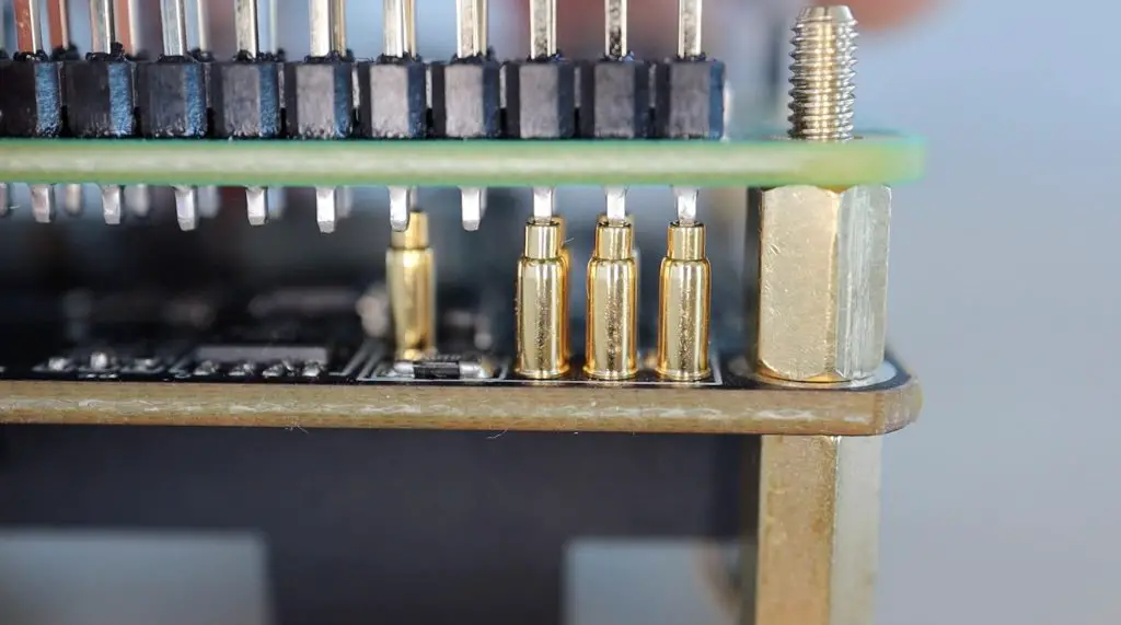
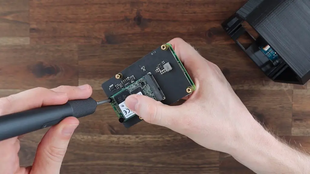
Screw the female-to-female standoffs to the SSD shield using a male-to-female standoff on the opposite side. The female-to-female standoffs go on the USB port side of the shield.
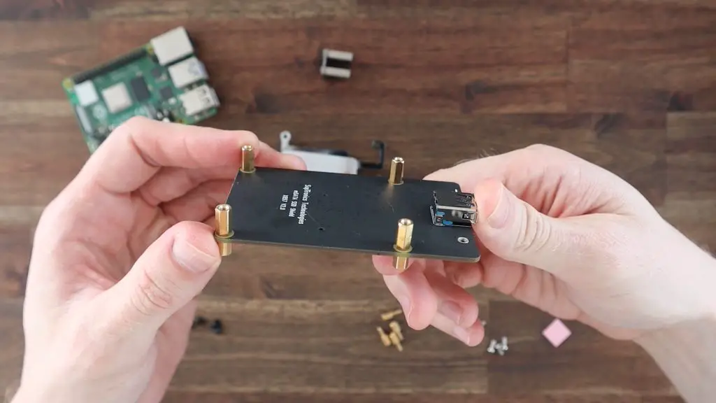
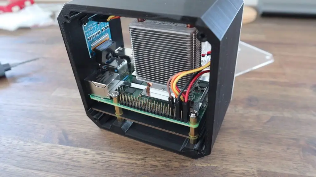
The Pi is then held on top of the standoffs with the second set of standoffs from the Ice Tower.
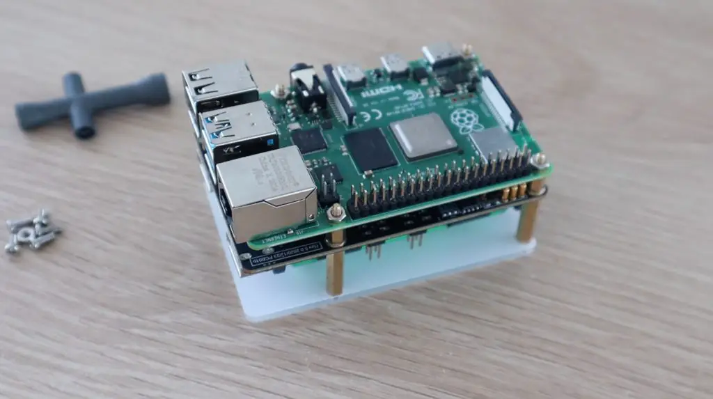
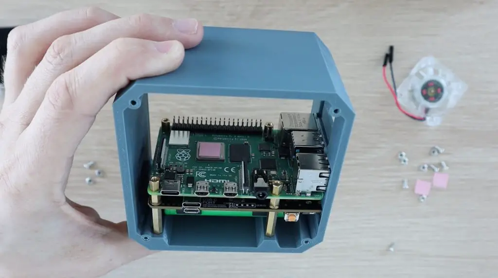
We can then add the Ice Tower to the Pi, remembering to first add the thermal pad on top of the CPU. The four silver screws hold the Ice Tower in place.
Our stack is now complete and ready to install in our case, so let’s modify the case design.
Designing and 3D Printing The Pi SSD Case
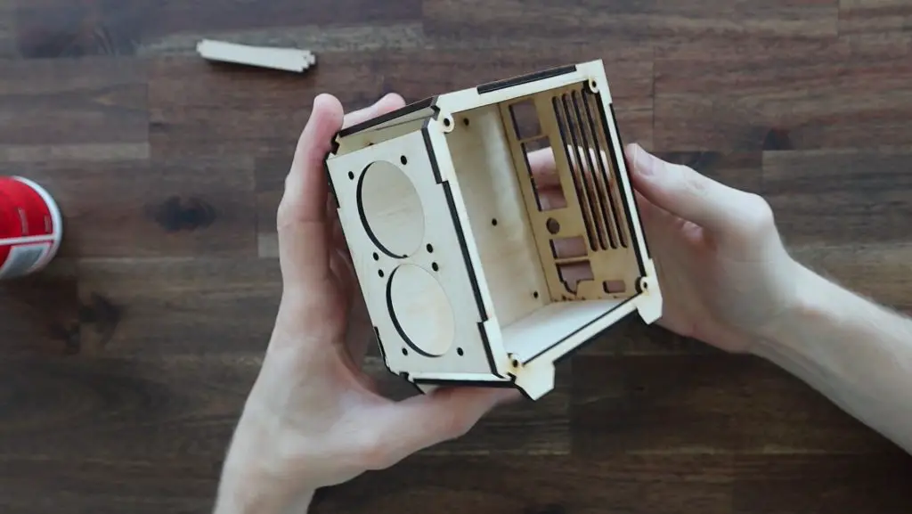
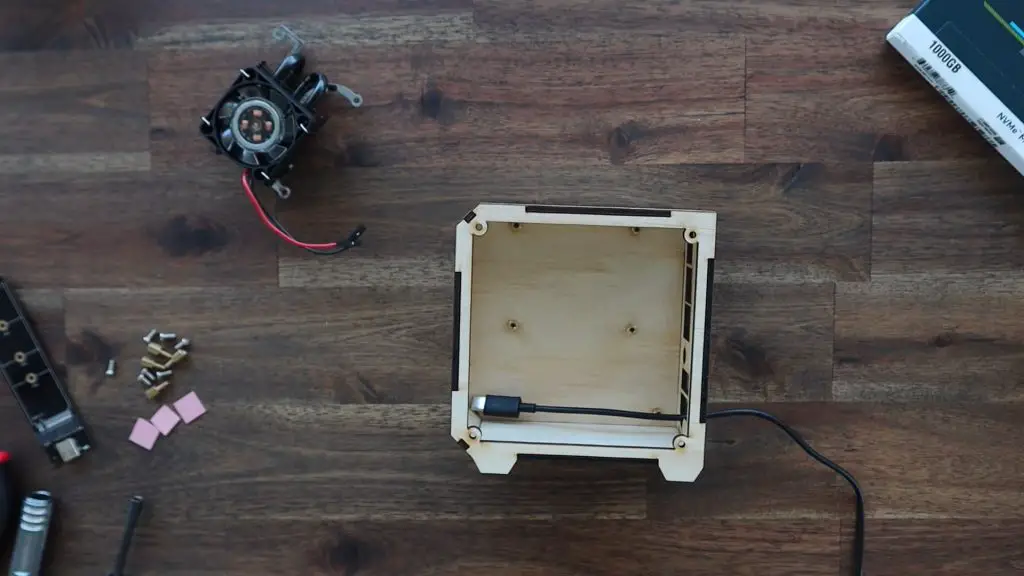
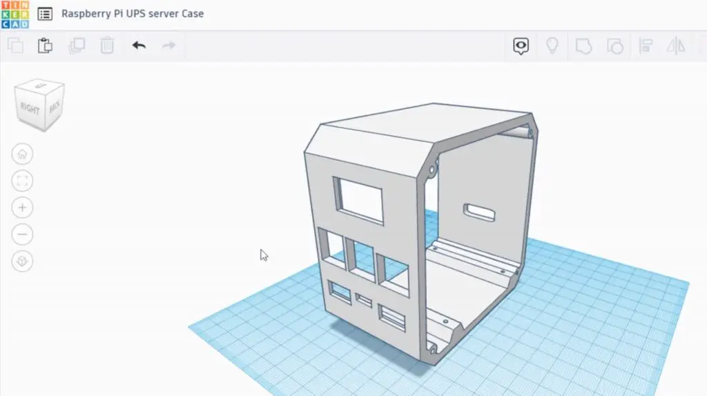
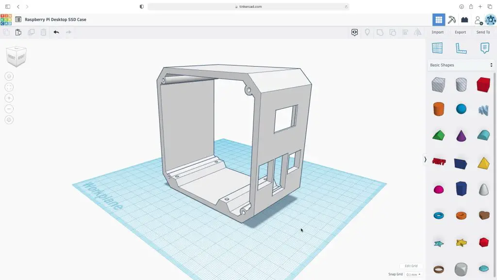
Now that we know what we’re going to be mounting in the case, we can start modifying the previous design to fit the SSD shield in underneath the Pi.
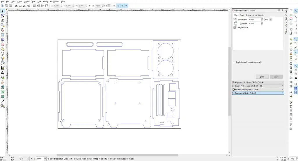
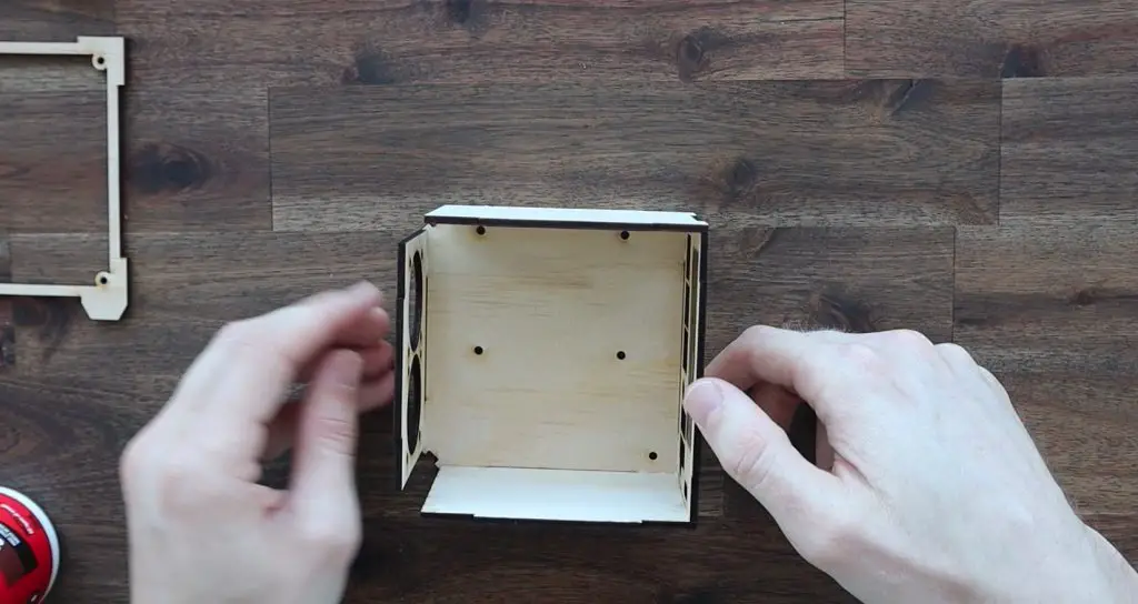
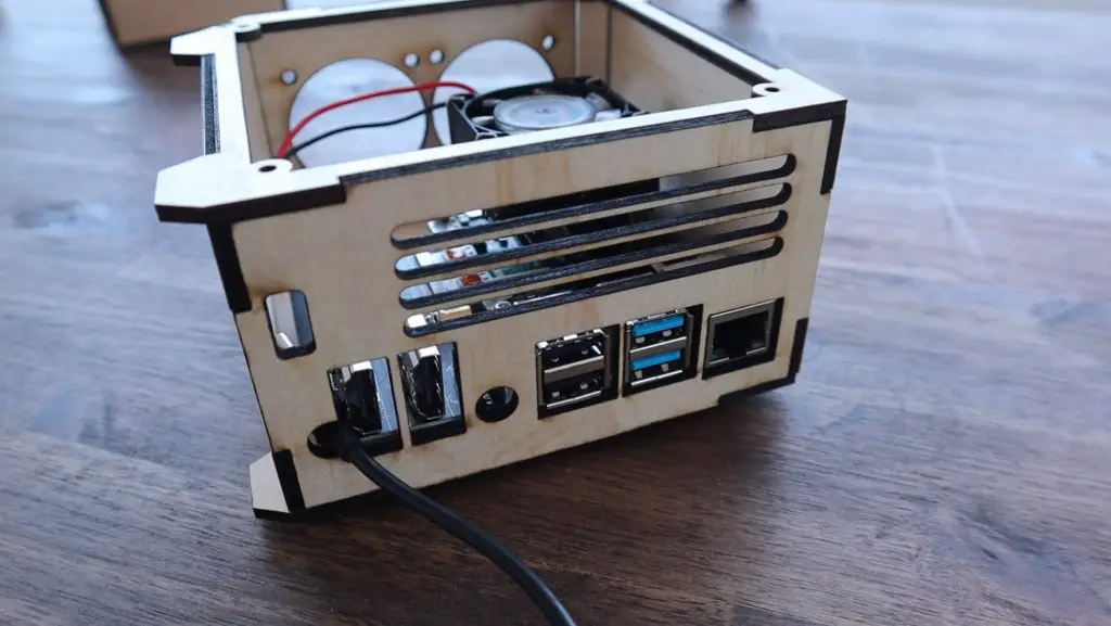
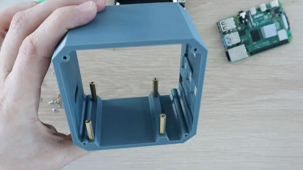
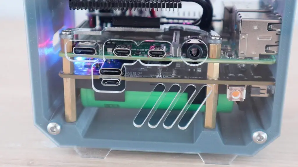
I took some measurements from the stack and adapted the design by moving the ports higher up on the front, slotting the middle USB port cutout to accommodate the jumper, and modifying the holes in the base to allow the screws to screw into the brass standoffs from underneath.
If you’d like to 3D print your own case, you can download a copy of the 3D print files, including a version with the ports on the back of the case, from the following link.
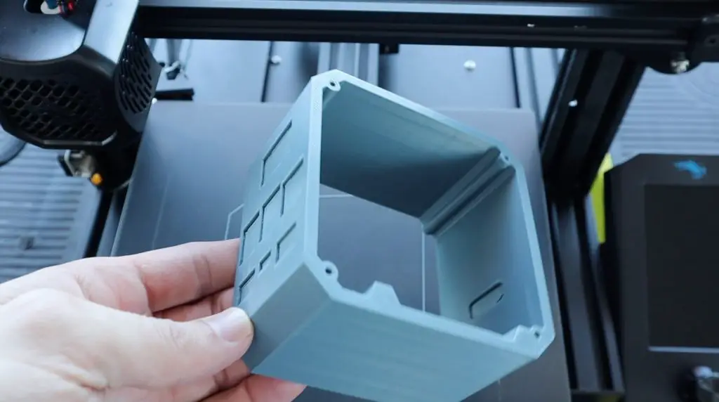
With the case design done, let’s print it out in Black PLA with a 15% infill. We’ll need to print it on its side and add some supports to the front for the ports.
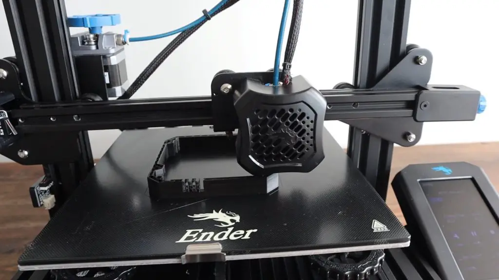
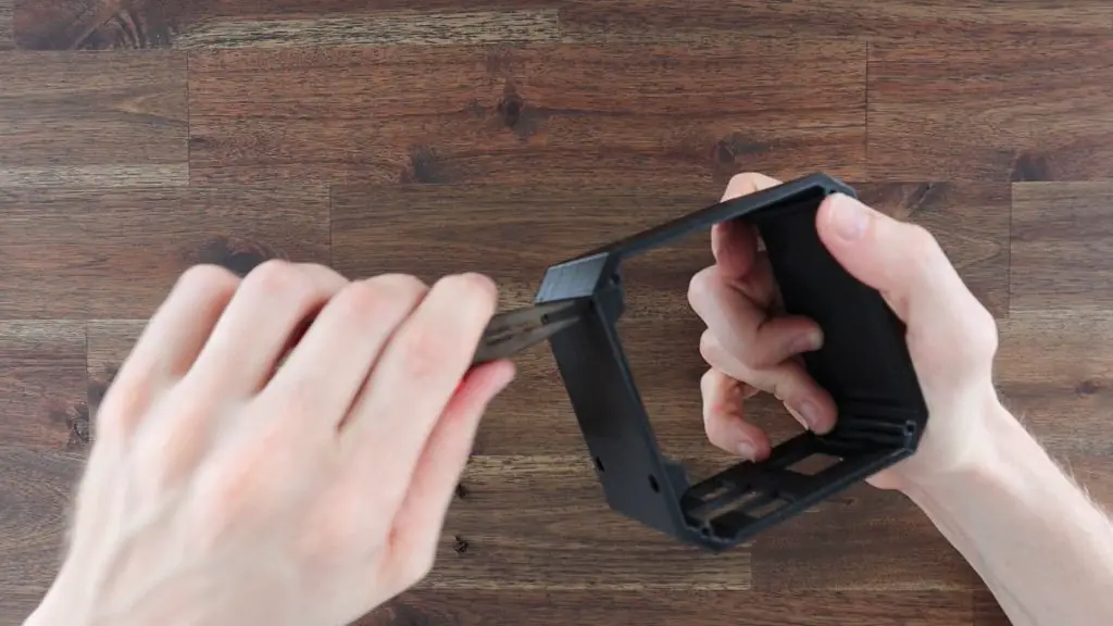
We then need to clean up the case and remove the supports before putting our Pi into it. Also, remember to remove the supports from the bottom holes in the case if you added them there as well.
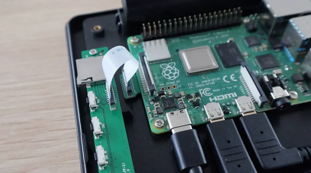
Installing The Stats Display
Last time, I put the Pi in before the display, but it’s actually a lot easier to put the display in first so that you’ve still got space to screw the bracket’s retaining screw in.
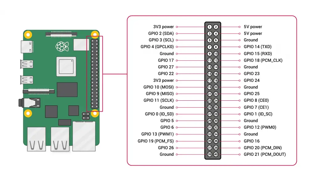
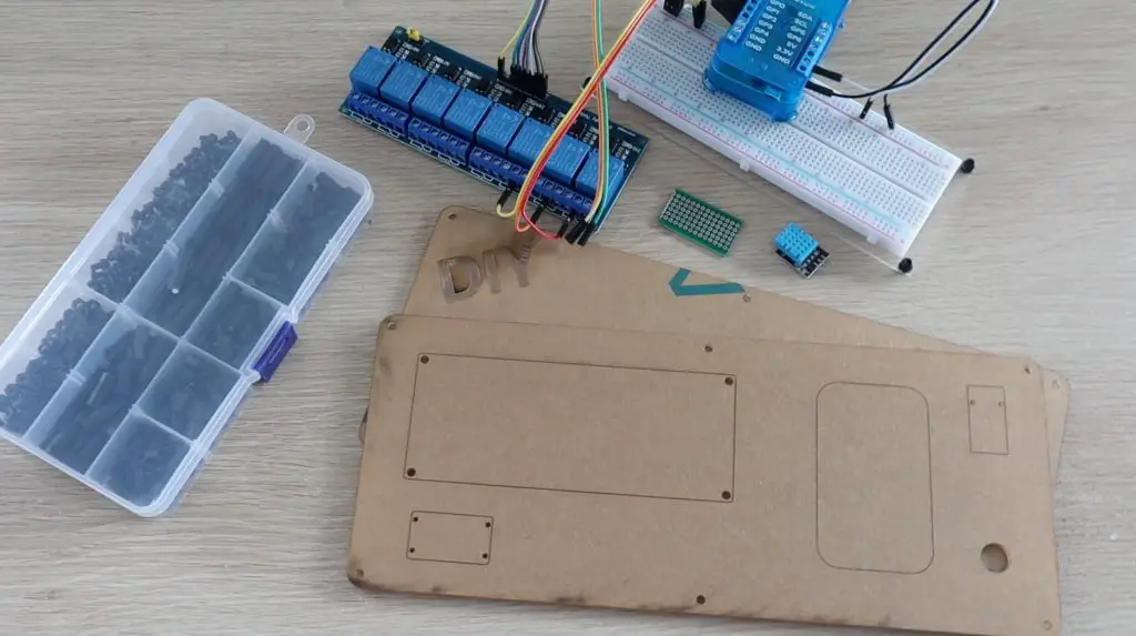
I’m using a small I2C oled display that is perfect to be driven straight from the GPIO pins. Make a note of your pin labels on the front of the pins before installing the display as they’ll be hidden once it is in place.
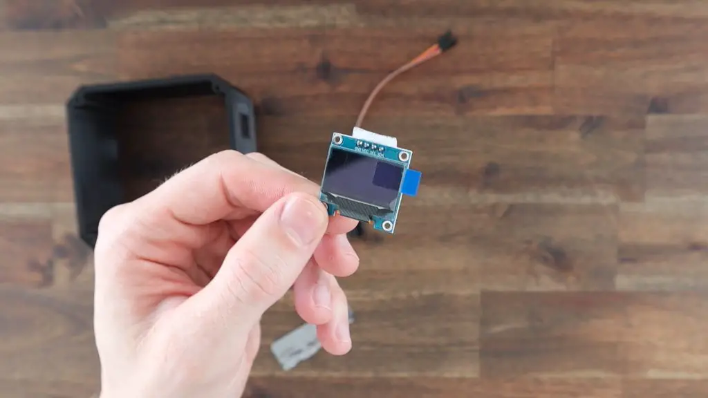
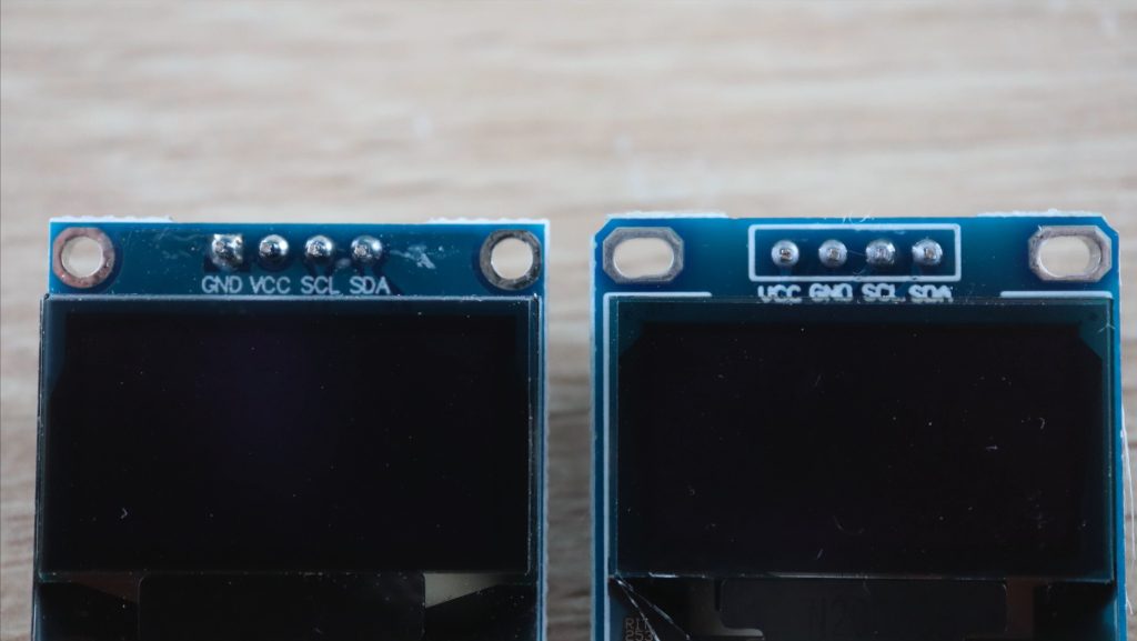
There are also two different versions of these displays online, and they have the VCC and GND pins swapped around, so don’t just copy my wiring because you might damage your display. They don’t have reverse polarity protection.
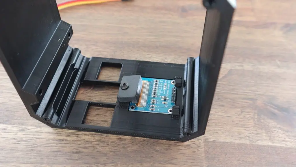
Slide the top edge of the display in underneath the top clips in the case and use the 3D printed bracket and black M3x8mm screw to hold it in place. Don’t screw it down too tightly or you might crack the display. This bracket just needs to gently hold it in place.
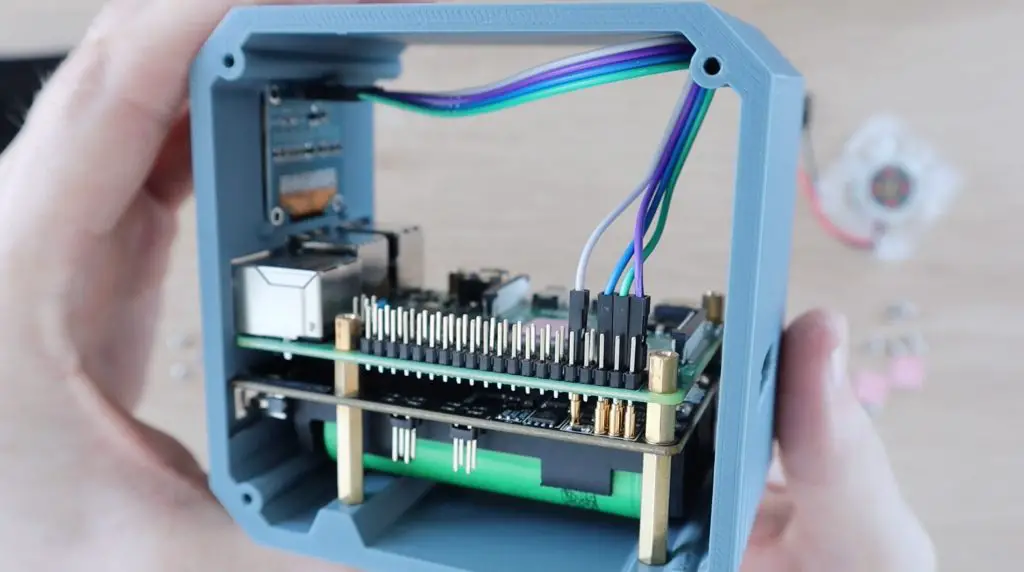
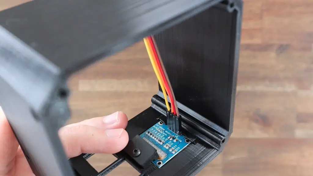
Push the ribbon cable connectors onto the pins on the back of the display. It doesn’t matter which colour goes onto which pin, just make a note of which way around yours are connected for now.
Installing The Raspberry Pi Stack Into Our SSD Case
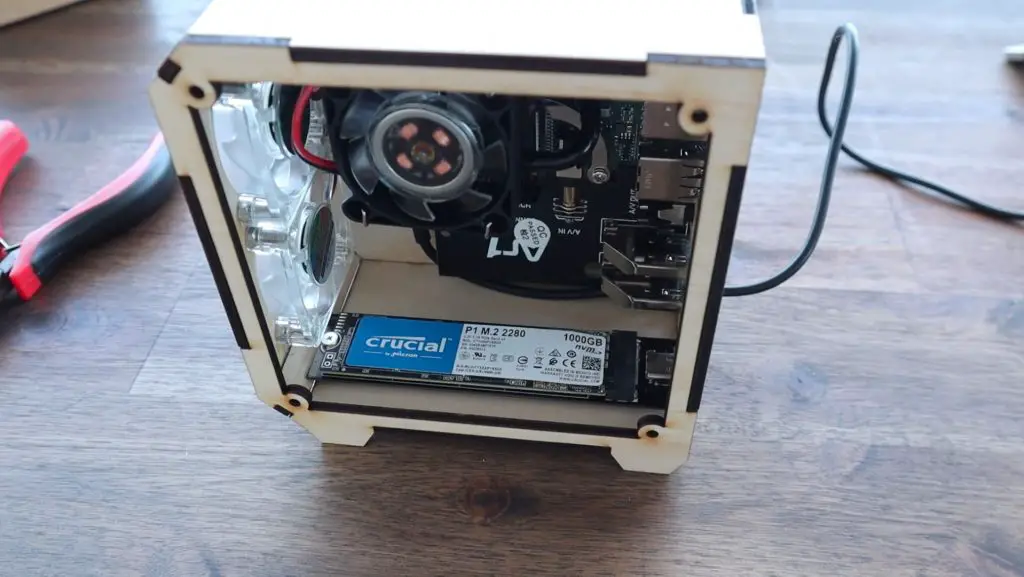
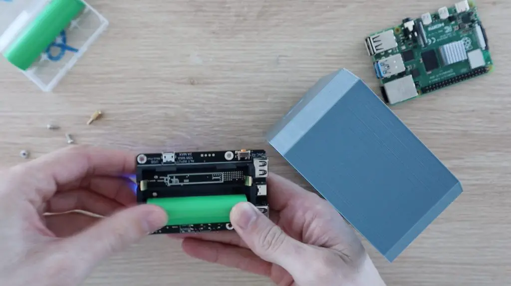
Before putting our Pi stack into the case, we need to install the SSD. I’m using a 128GB drive as this is just a secondary computer for me. You can use up to a 2TB drive if you’re going to be using yours as a NAS or media centre.
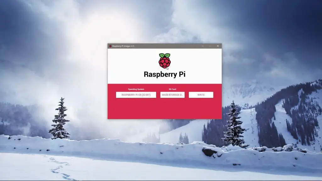
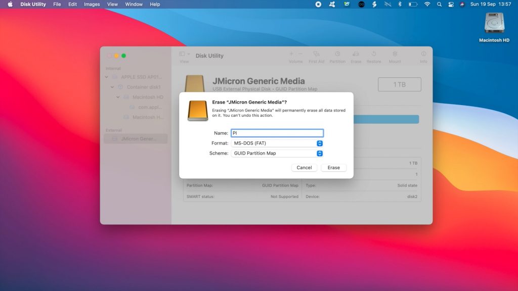
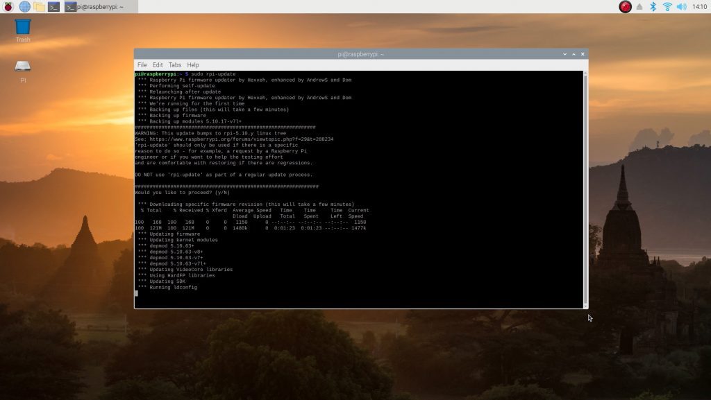
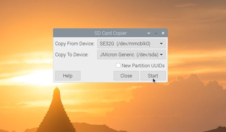
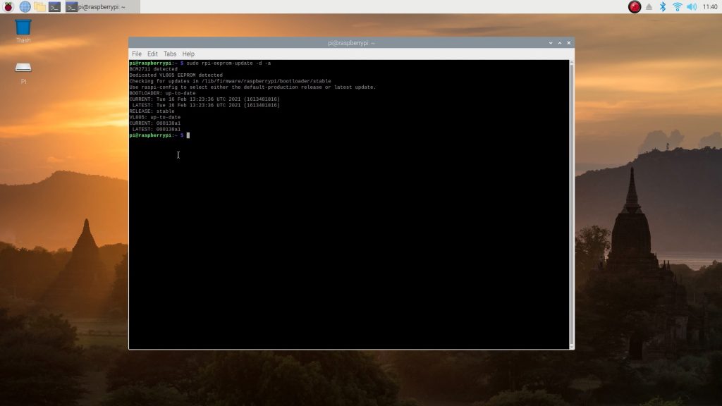
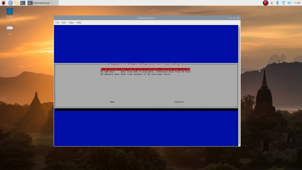
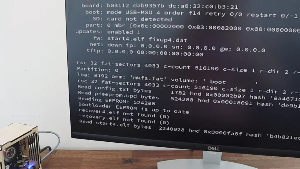
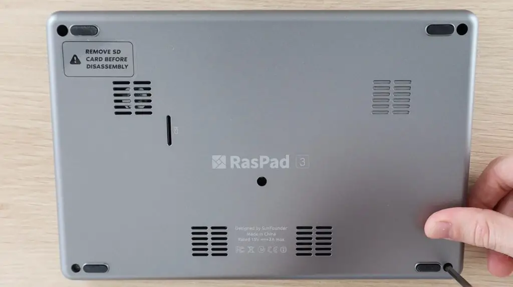
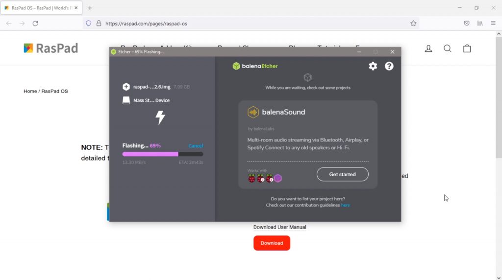
You’ll also want to configure your Pi to boot from the SSD and flash the operating system image to your SSD before putting it into your case, as you can’t get to the SD card to remove it after the Pi is installed. The Pi also often isn’t able to supply enough power to power two SSDs simultaneously. So if you intend on copying the operating system image from another SSD, you’ll need to use a powered hub or self-powered drive.
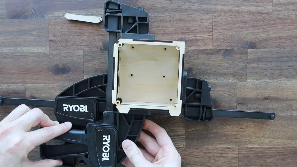
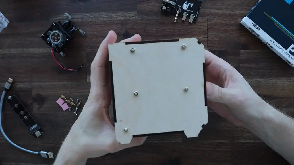
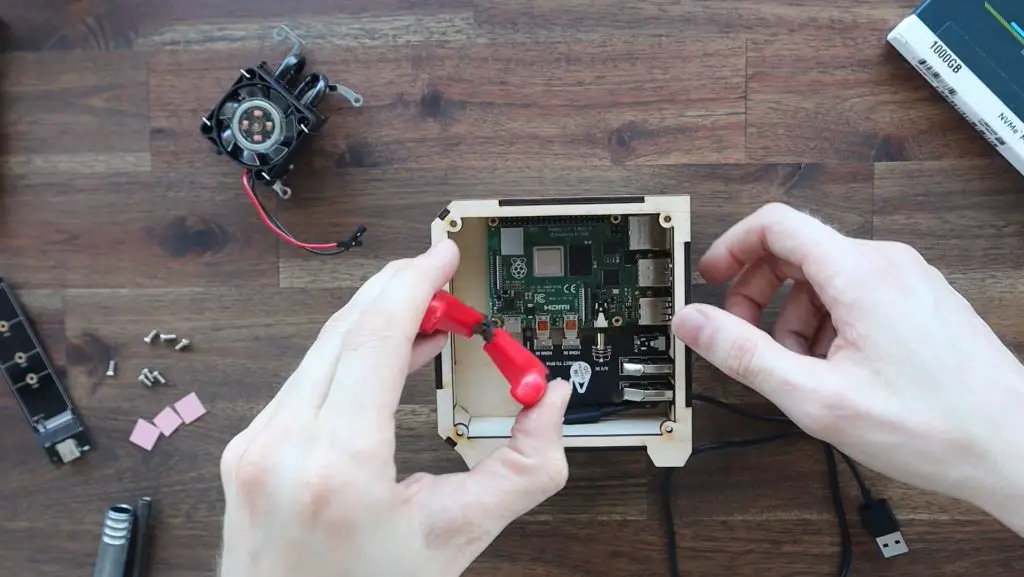
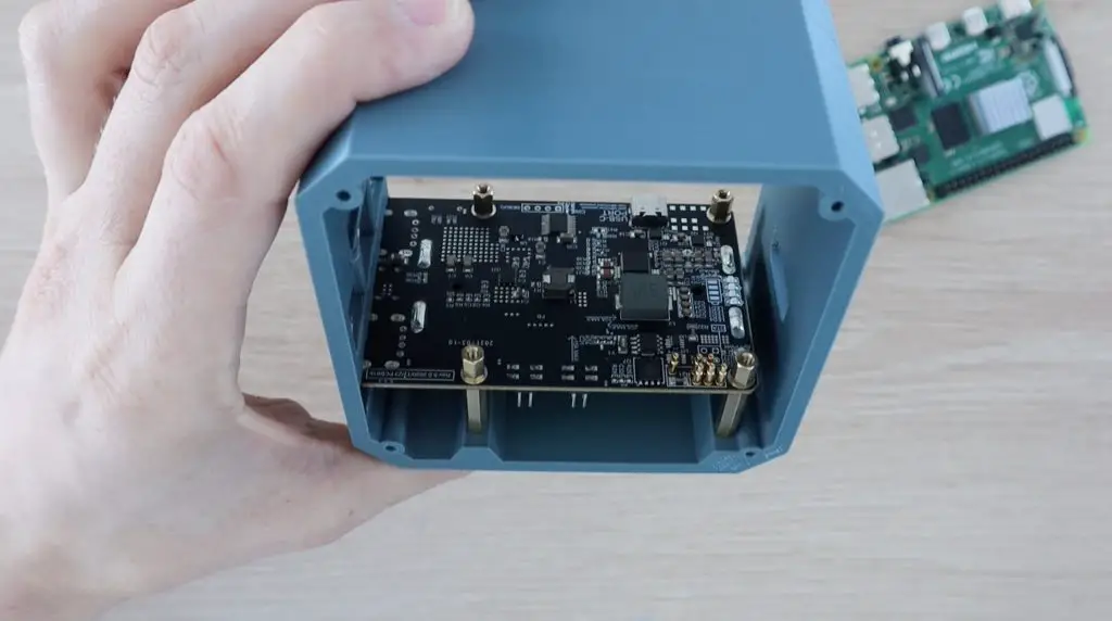
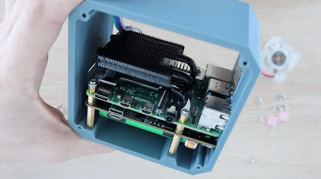
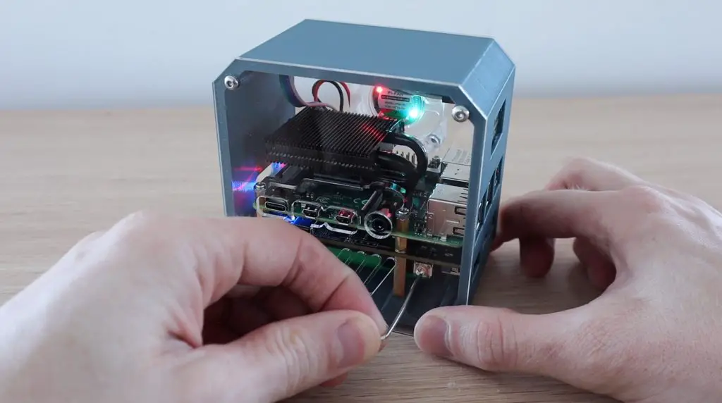
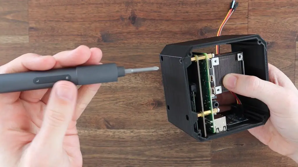
Put the Pi stack into the case and secure it with the small black screws which go through the holes in the base and into the brass standoffs.
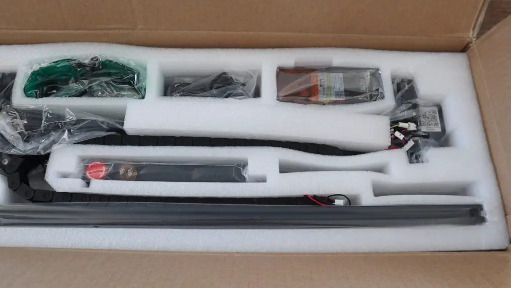
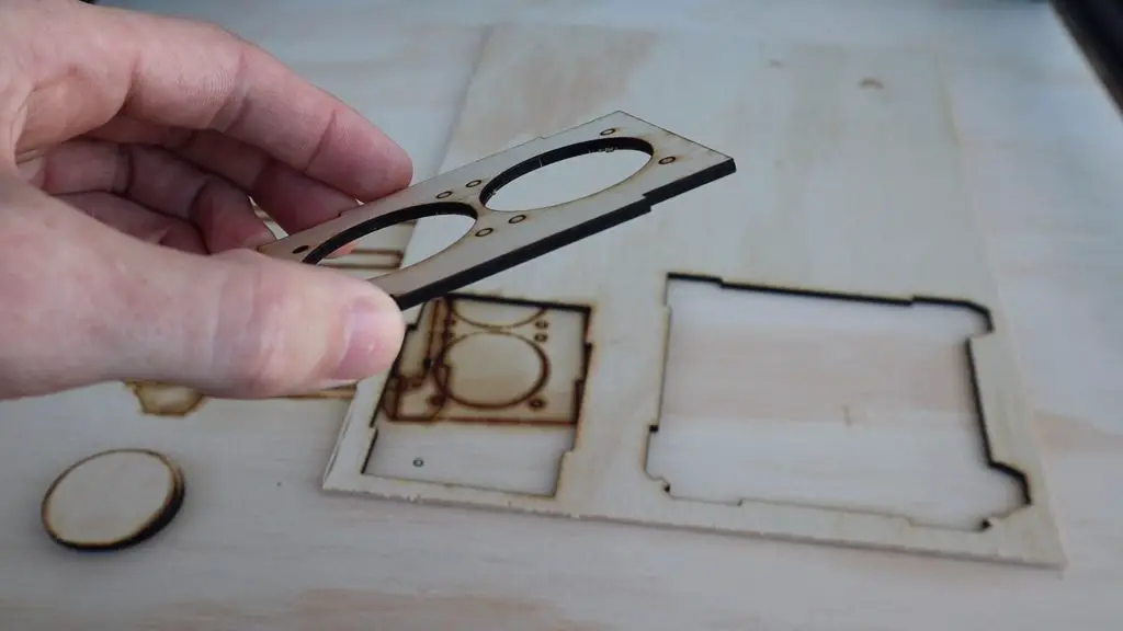
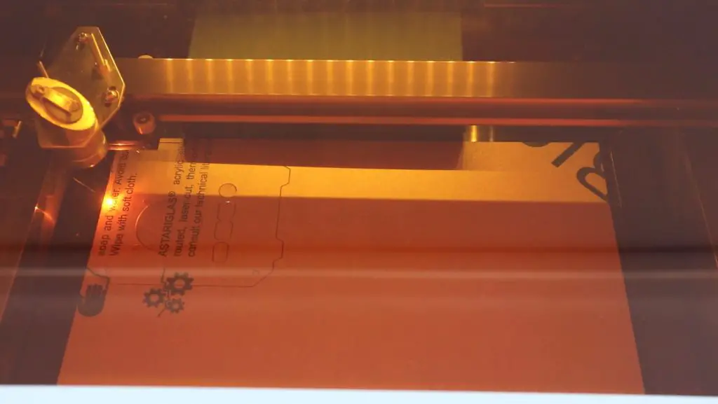
Making Up The Acrylic Side Panels
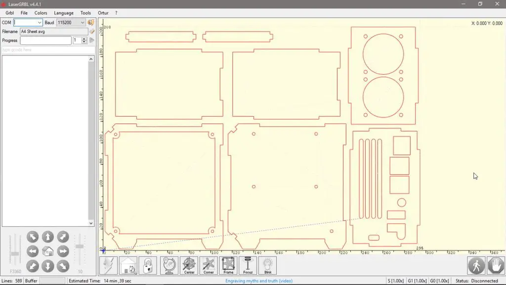
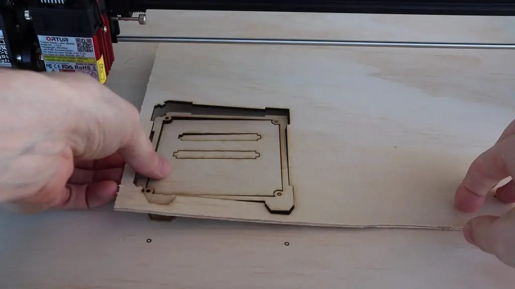
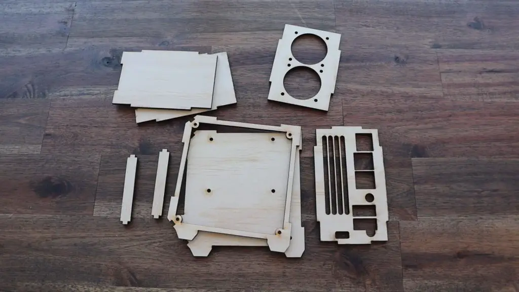
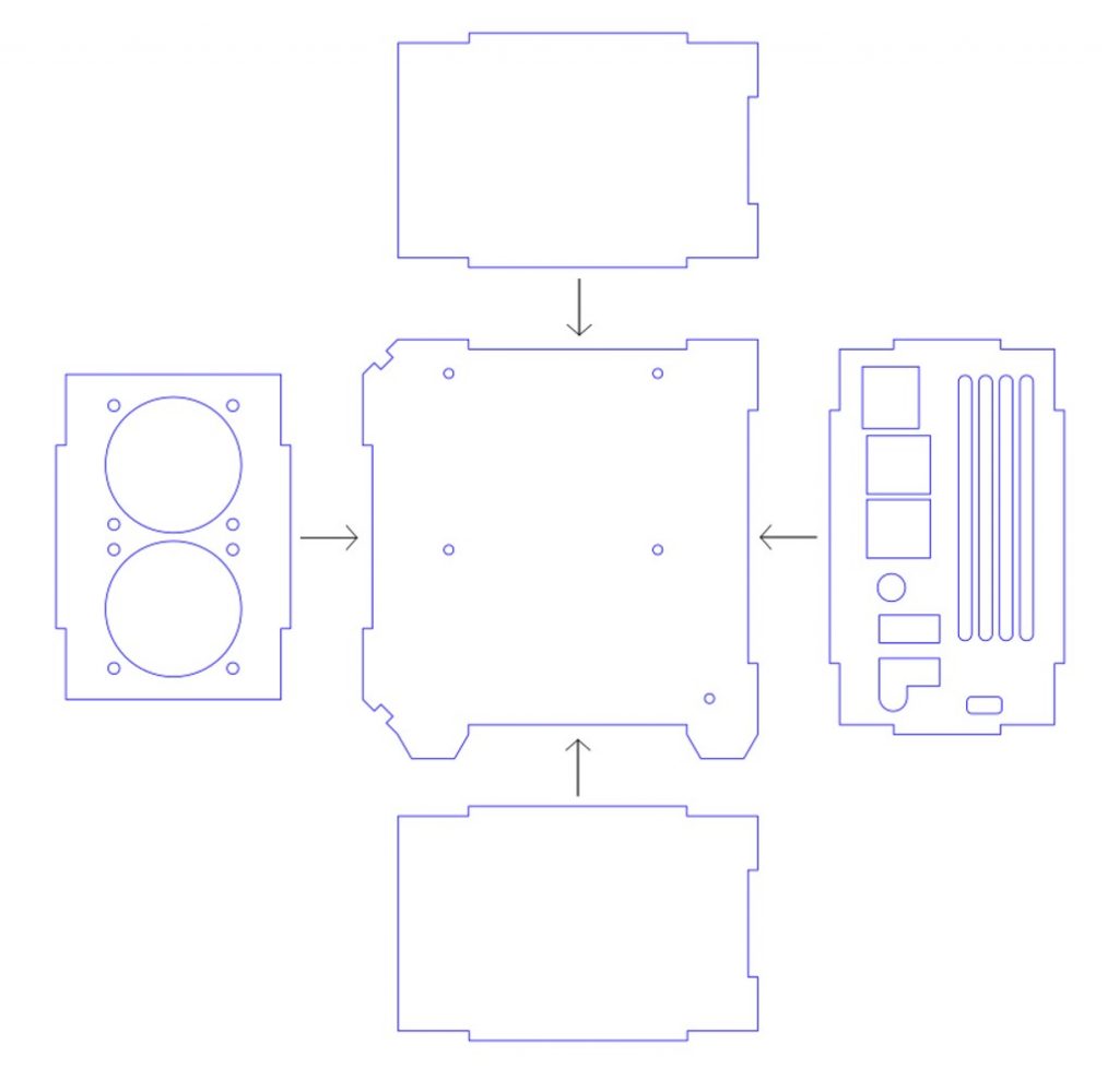
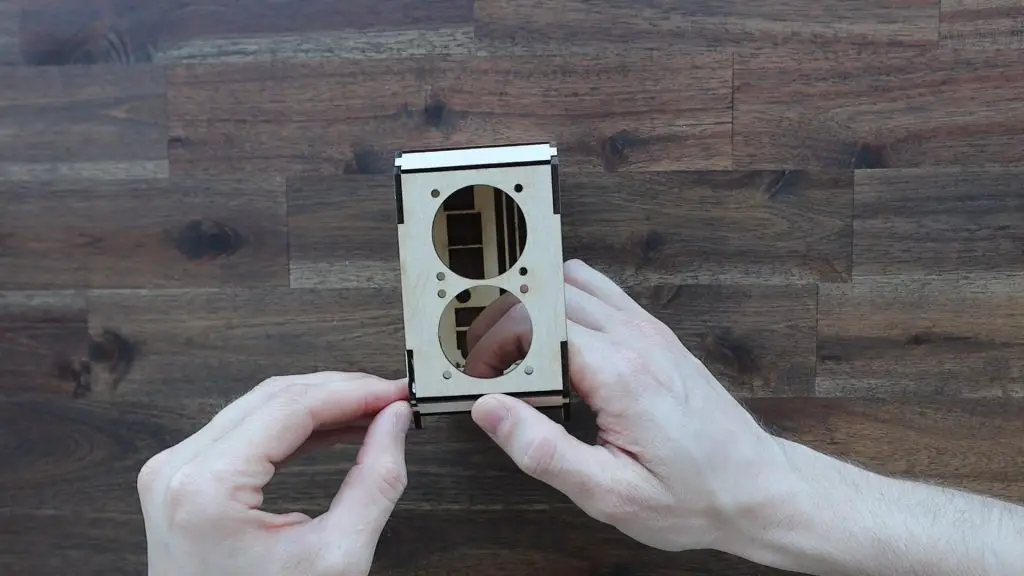
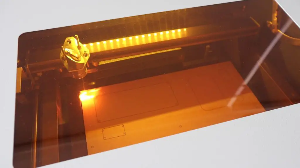
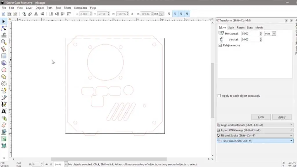
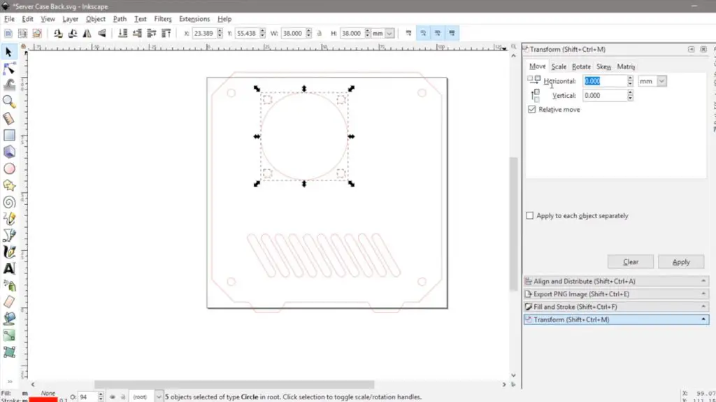
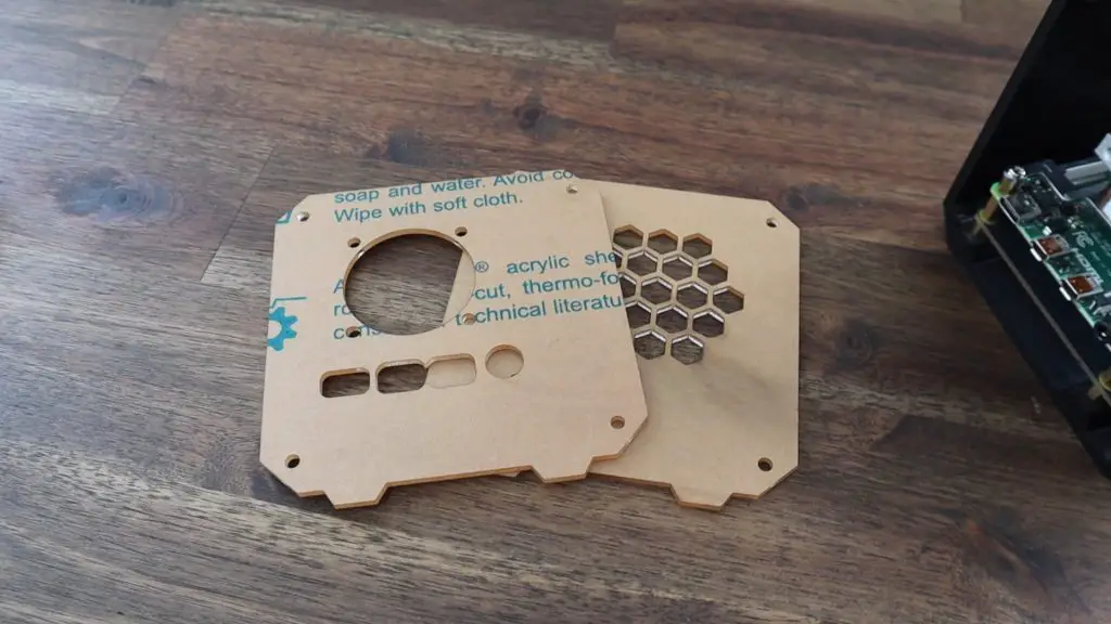
Now we just need to close up the sides of the case with our acrylic side panels. I’m going to laser cut these from some 2mm clear acrylic. If you don’t have access to a laser cutter, you can either buy them as part of my kit or cut your own by hand using a fine-tooth saw to cut the profile and an electric drill to make the screw and vent holes.
The template and laser cutting file for these side panels is available in the same download as the 3D print files for the case. I’ve also included a 3D printable version of the panels. They won’t be clear if they’re 3D printed but give you another option if you can’t get the side panels made up.
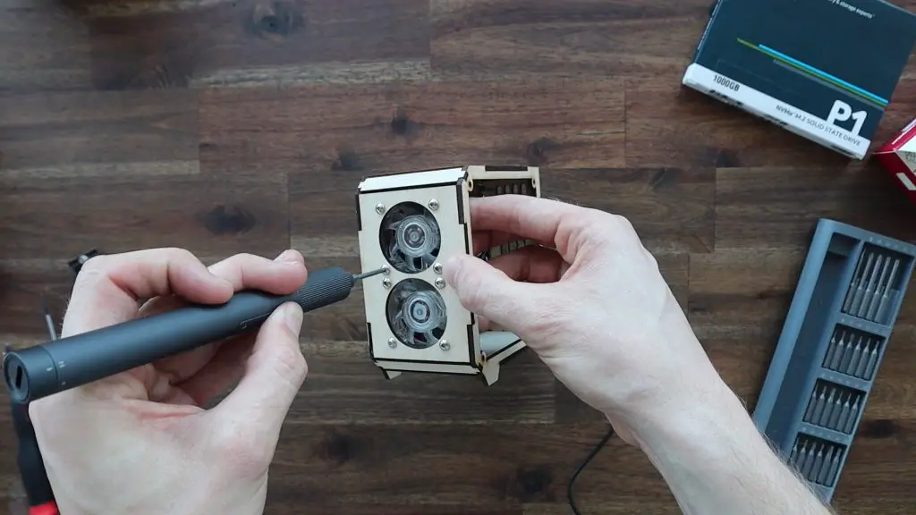
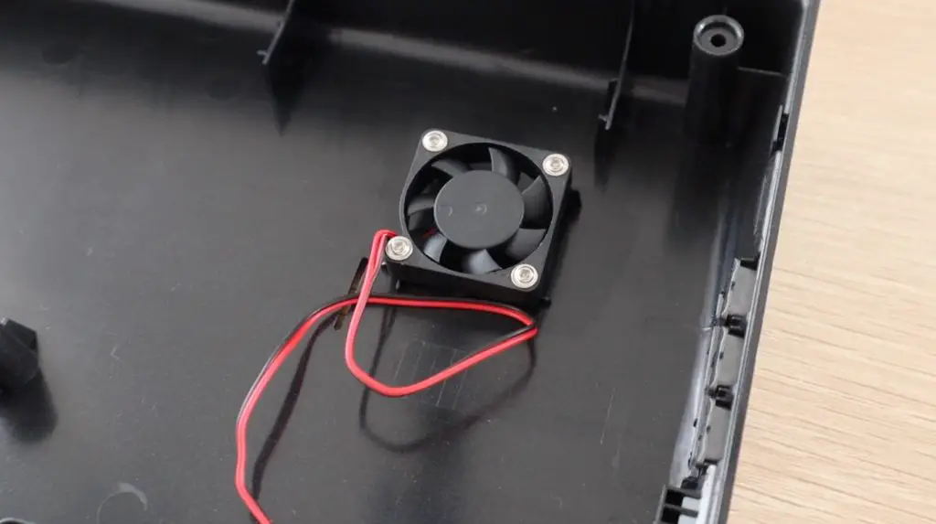
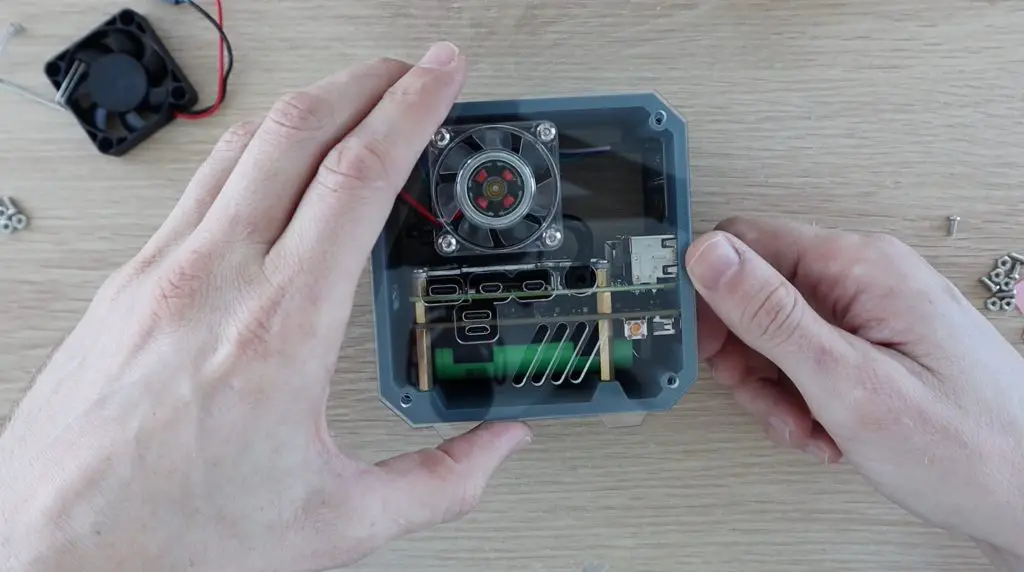
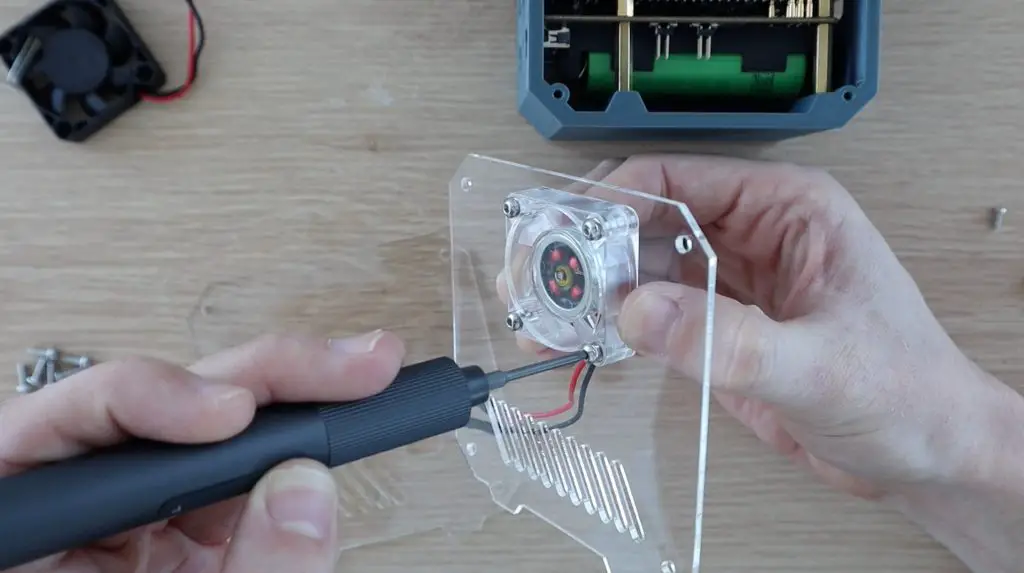
To mount the fan onto the side panels, we need to push four M3 nuts into the pockets on the fan. These enable us to use the existing screws that come with the Ice Tower to hold the fan in place.
This is easiest done by putting the nuts down on a flat surface and gently pressing the fan pocket down onto each one.
The nuts sit on the acrylic side of the fan, so the fan is held using the press-fit on the nuts, the screws don’t go all the way through the fan.
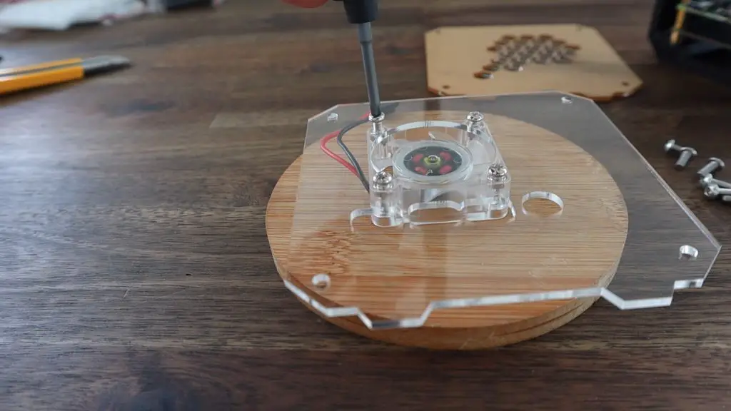
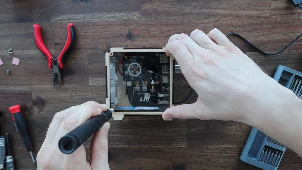
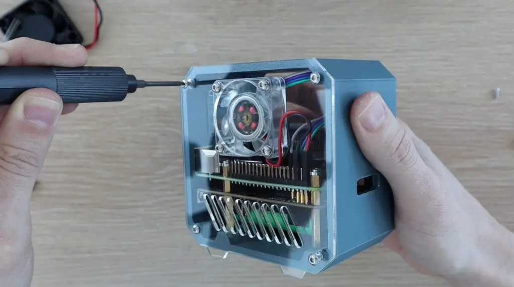
The side panels are then each held in place with four M3x8mm button head screws, one in each corner. Don’t overtighten these screws as it is very easy to strip the 3D printed plastic and they’ll then be a bit loose.
Before putting the opposite side panel on, you’ll need to connect your display and fan to the GPIO pins. I connected my display to power and the I2C pins and the fan to 5Vs. If you need help with this and programming the display, follow my guide on connecting and programming the OLED stats display.
We can now close up the second side with the next four M3x8mm screws.
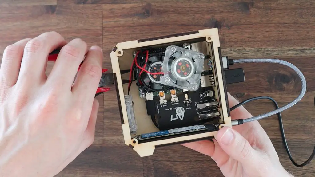
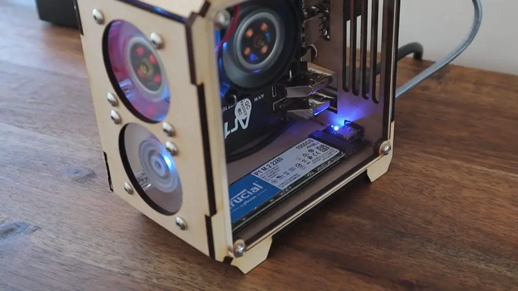
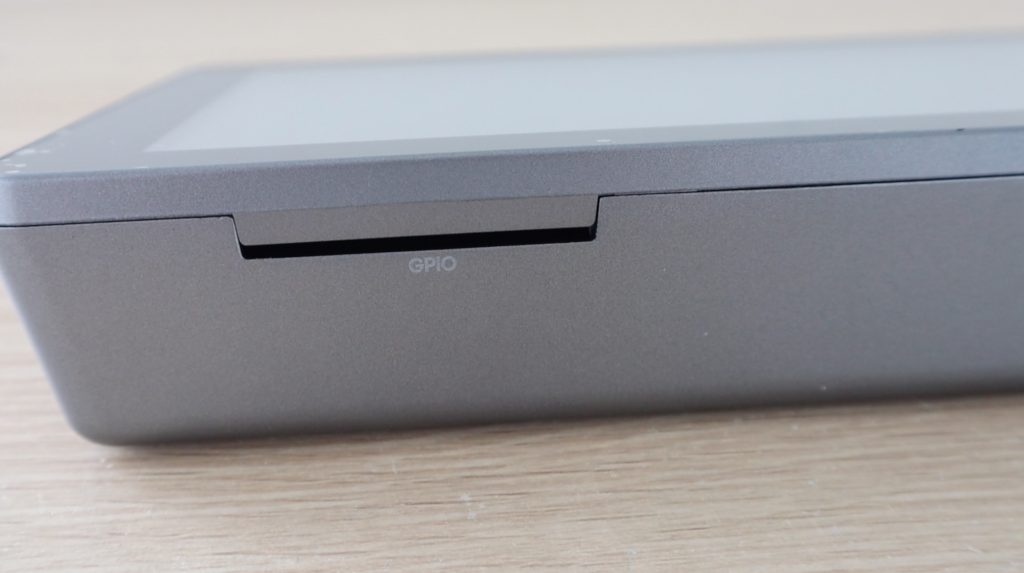
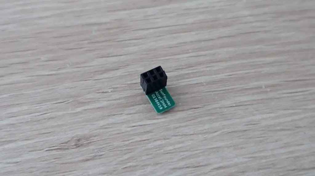
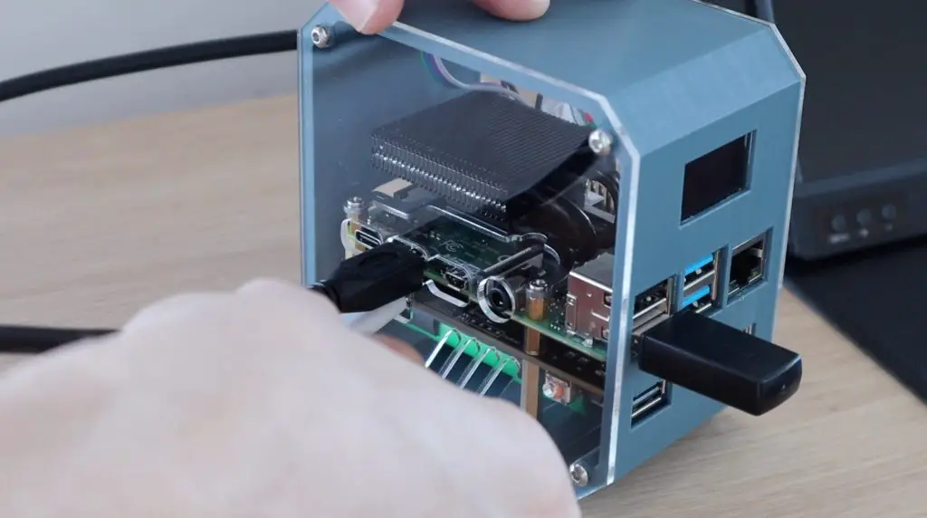
Lastly, let’s plug our USB jumper into the shield and Pi. I 3D printed a small cap to cover the jumper and make it blend in with the case a bit better.
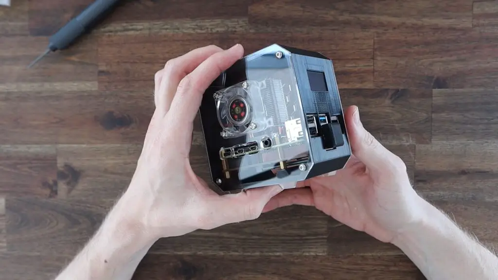
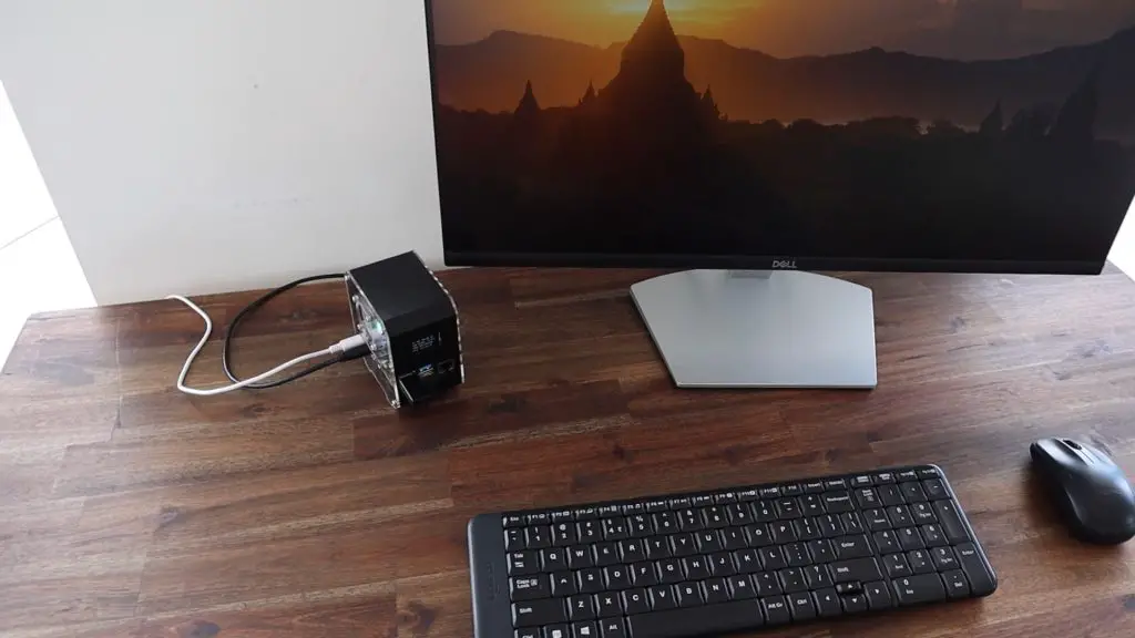
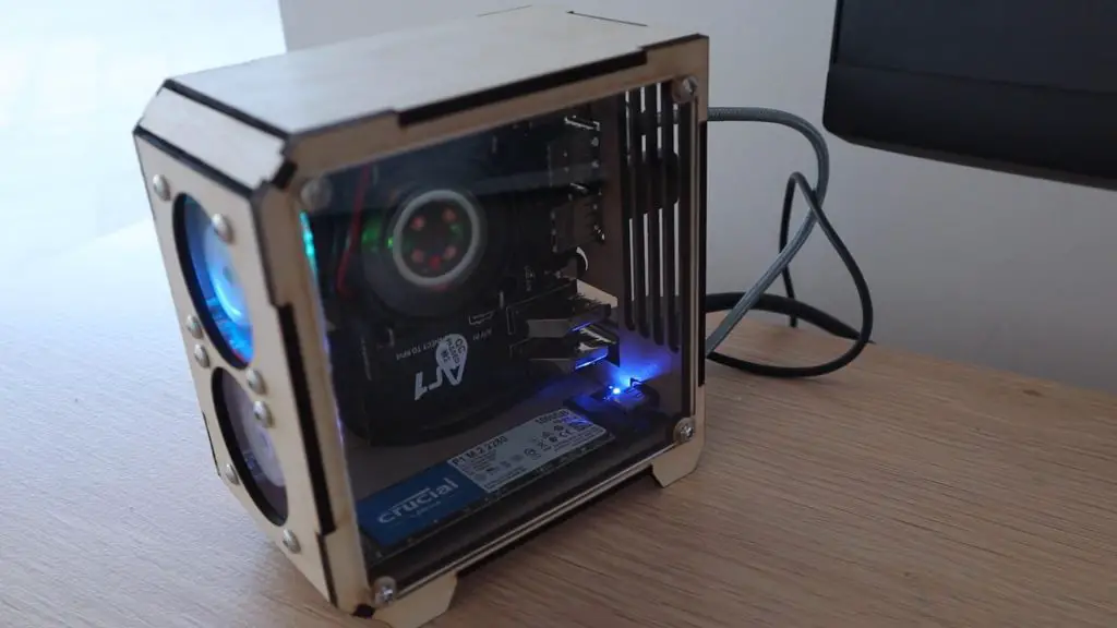
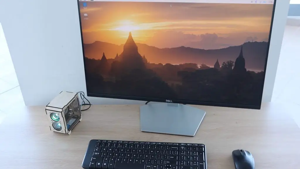
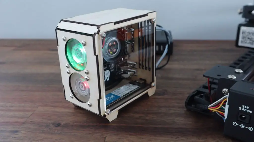
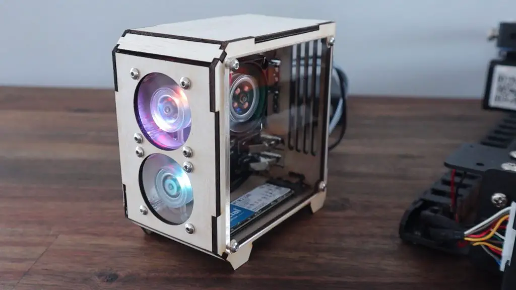
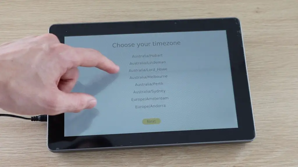
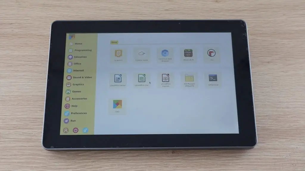
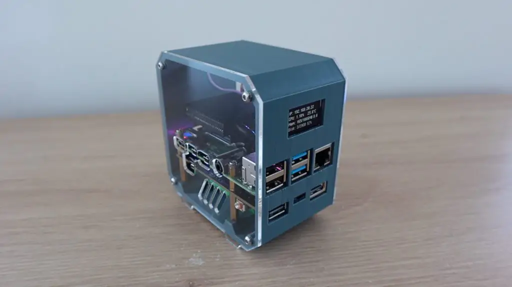
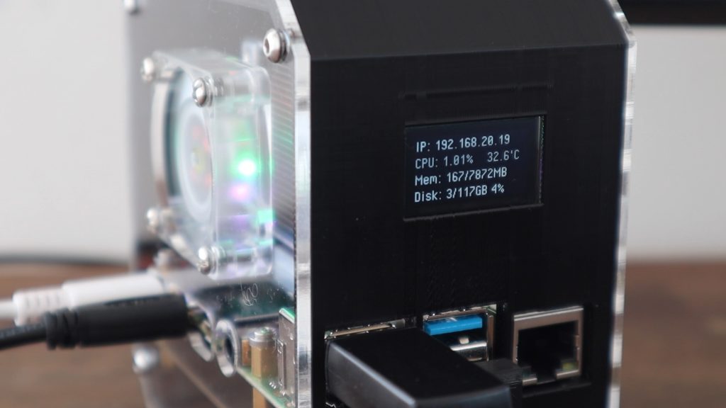
The Completed Pi SSD Case
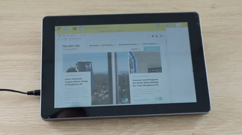
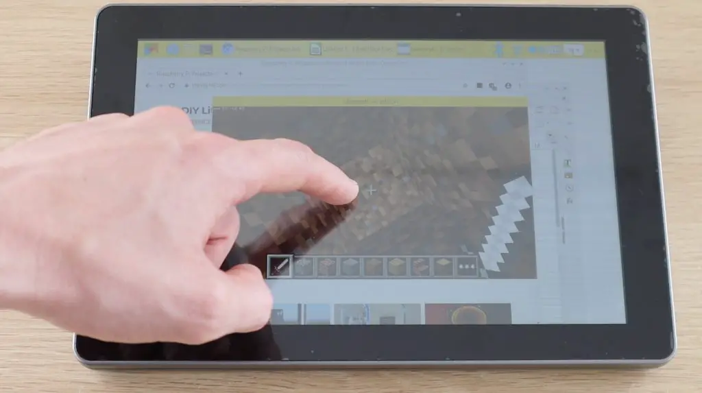
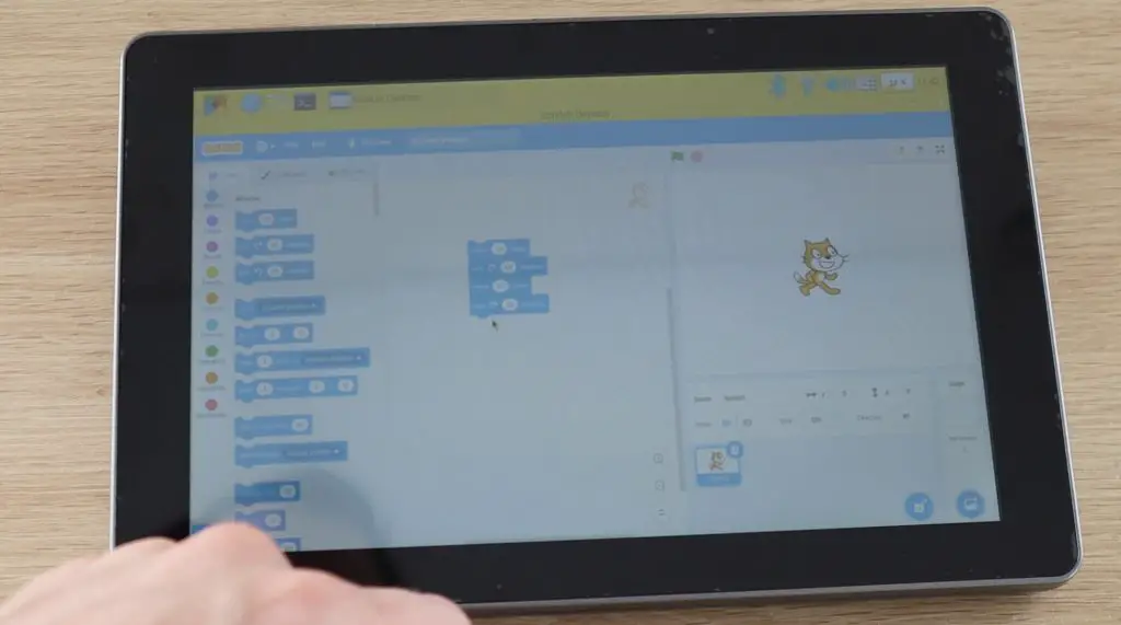
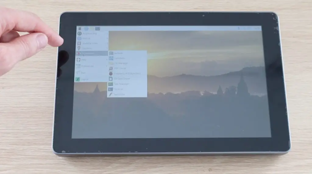
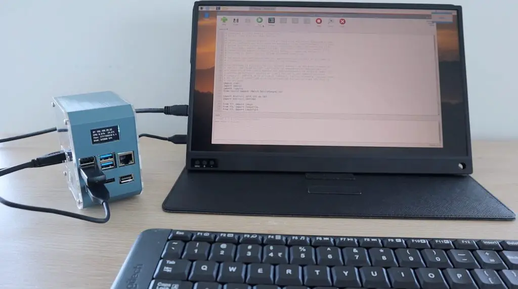
Our Pi SSD Case is now complete, so let’s turn it on and try it out. Mine will work right away as I’ve cloned my SD card from the previous project which already has the stats display programmed to run on startup using crontab.
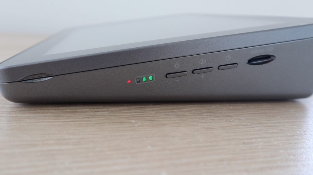
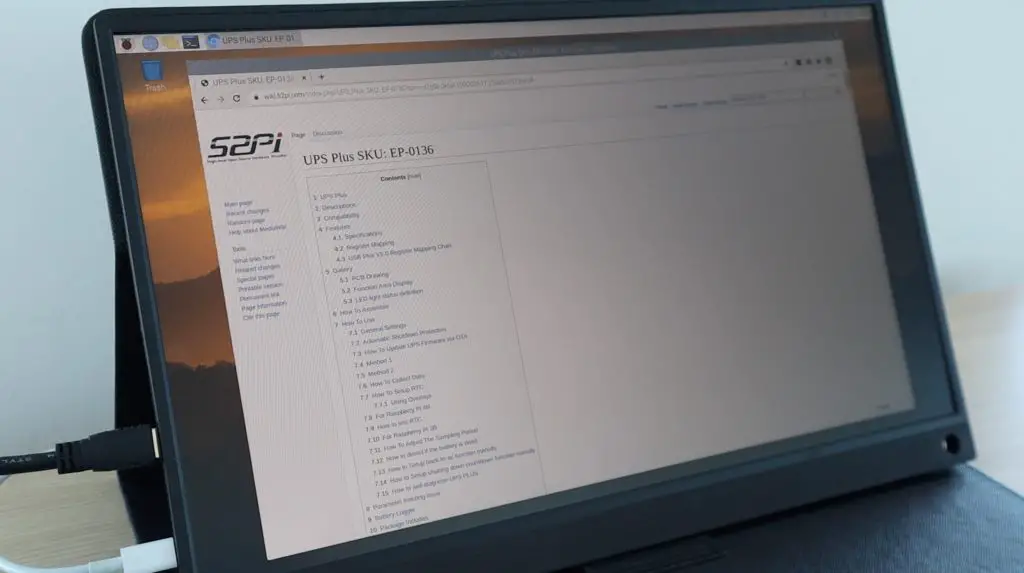
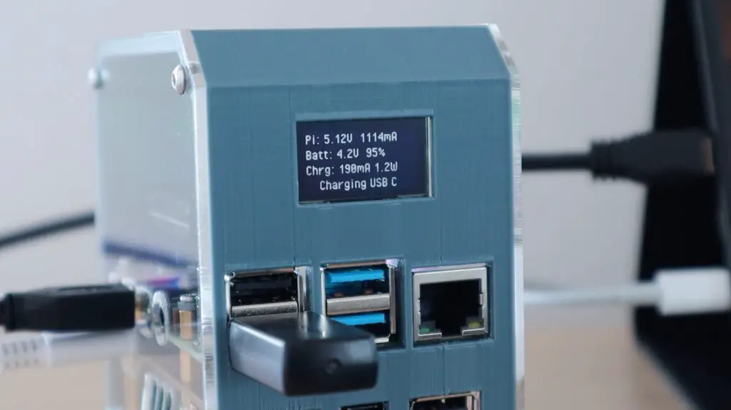
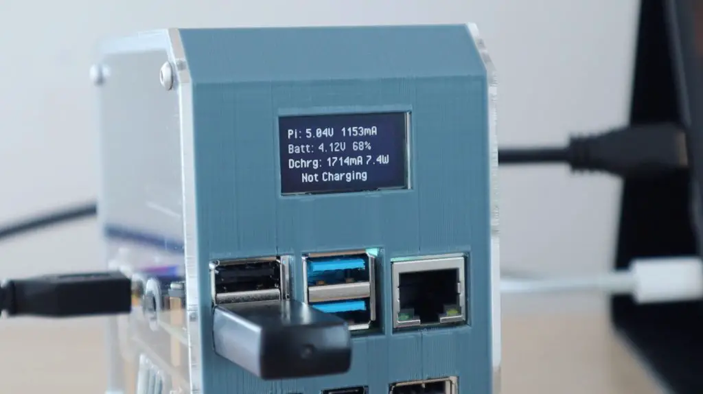
The display shows your local IP address, which is useful for network-related projects, as well as the CPU load, CPU temperature, memory and disk usage. The python script is fully customisable, so you can add or remove stats as you’d like and even integrate stats from other utilities like Pi-hole or Openmediavault.
Let me know what you think of the case in the comments section below. Are you going to try to build your own?