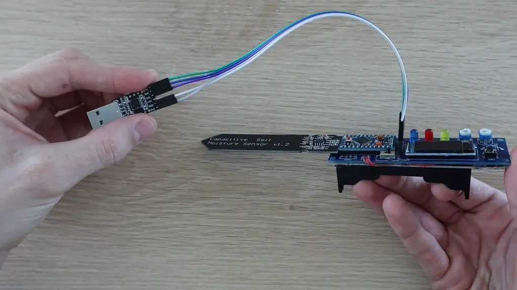
Are you stressed by your schedule and struggling to stay organized? Then a bullet journal may be just what you need! The bullet journal, also called a “BuJo” for short, was created by Ryder Carroll and has become a huge help for people to take control of their lives. As a beginner, it is easy for you to start a bullet journal to organize your work, home, hobbies, and any other areas that matter to you. One journal can be used for everything! Stay flexible and customize the journal to fit your unique needs.
Starting a bullet journal will help you to be organized in every part of your life. It will serve as your planner and your journal. Having a bullet journal will reduce your stress and anxiety and help you to create achievable goals with action steps to reach them. It also provides you a creative outlet, as you can decorate your journal as much as you like, and it can become a pretty keepsake for years to come. The best part is that it does not take much to get started, just a notebook and pen!
The Notebook
You can use any notebook or journal, but I would suggest a larger notebook with heavier paper to avoid bleeding and ghosting. You also will want one that is easy to open and write in. The good thing is that almost anything will work, depending on your preferences! One popular journal is the Lechtturn 1917 which has numbered pages, a built-in index, two ribbons, excellent paper to use with watercolors, brush pens, and fountain pens, and a variety of colors and grid versions (plain, ruled, graph paper or dot grid).
The Pen
Like the notebook, any type of pens or markers will work to begin your bullet journal depending on what works for you. You should strive to find a good nice quality pen or set of pens that you can write with comfortably on a daily basis. It is also nice to have a variety of colors. A favorite option of many is using a fountain pen. There are many great fountain pens that are extremely fun to write with as the ink glides effortlessly over the page with less pressure. Fountain pens provide a more unique writing style that can be changed by the type of nib, hold, and angle of the pen. A good pen can be the motivation you need to start writing in your journal every day!
Getting Started With Your Bullet Journal
Now that you have all that you need to get going, here are a few basic things to consider when getting started.
Create an index where you can keep track of all of your pages. You can use any format, but an easy one is just to have two columns: one for the page content and one for the page numbers. Remember to keep your index updated as you create new pages.
Create a key for all of the symbols that you want to use in your bullet journal, making it easier to keep your entries and to-do lists brief. You can be as creative or as simple as you want. For example, you can use happy and sad faces to represent your mood on that day, checkmarks for accomplished tasks, and stars for very important events.
Create your first monthly page. This is a wide view of the month. Typical formats include some sort of calendar or lists of dates. I also suggest having a place to write out your monthly goals.
Create your weekly and daily logs. These sections are where you put all of your regular daily notes, your schedule and to-do lists of tasks to be accomplished.
Decide on additional sections (collection) that you want to have in your bullet journal that are important to you. Some examples include future goals, finances, savings plan, diet and fitness, meal planning, date night ideas, a mood tracker, and a gratitude log. There are endless possibilities for what you can include.
Decorate your bullet journal and make it your own. Let your creative side show by jazzing up your journal with watercolors, hand lettering, modern or traditional calligraphy, original artwork, doodles, stamps, and stickers.
Now it is time to start your own bullet journal. Remember to have fun and make it your own!
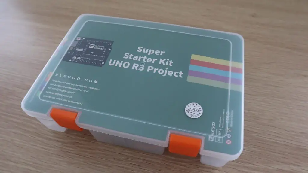
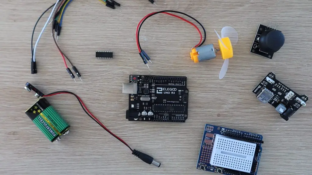
Elegoo is one of the popular names in the Arduino starter kit spaces, making great value starter kits with a good instruction set to get you started tinkering with Arduinos and electronics. They sent me their Uno project super starter kit to try out and share with you. So, I’ll be doing just that and sharing two small projects which I built using the kit as well.
The kits are available through their Amazon storefronts in a number of different countries.
You can watch my video of the unboxing and projects here, or read on for the write-up.
Unboxing The Elegoo Uno Project Super Starter Kit
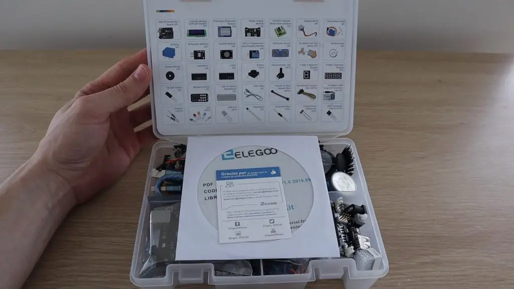
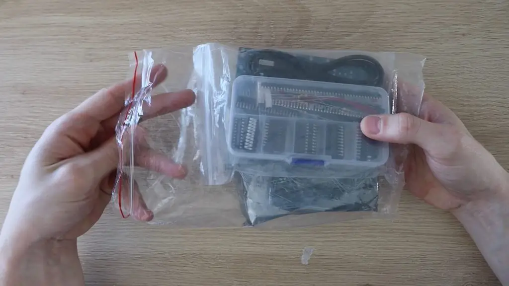
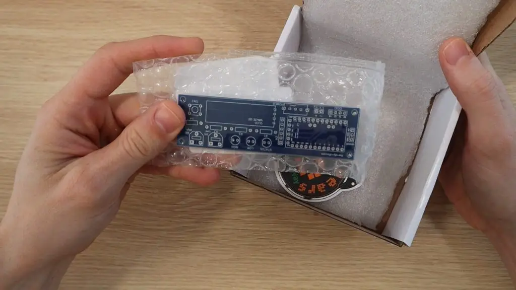
As expected from Amazon, the kit arrived really quickly and was well packaged and protected. The kit arrived in the usual bubble-sleeve Amazon-branded package and inside it was this yellow package, which Elegoo themselves have wrapped up as well.
Inside this yellow package, the kit is packaged into a plastic storage case, which is great for keeping all your components together after you’ve started using them.
The super starter kit case is pretty tightly packed when you get it, but once you’ve removed the plastic packaging and foam pieces for shipping, you shouldn’t have a problem getting the components back into the box again once you’re done with a project.
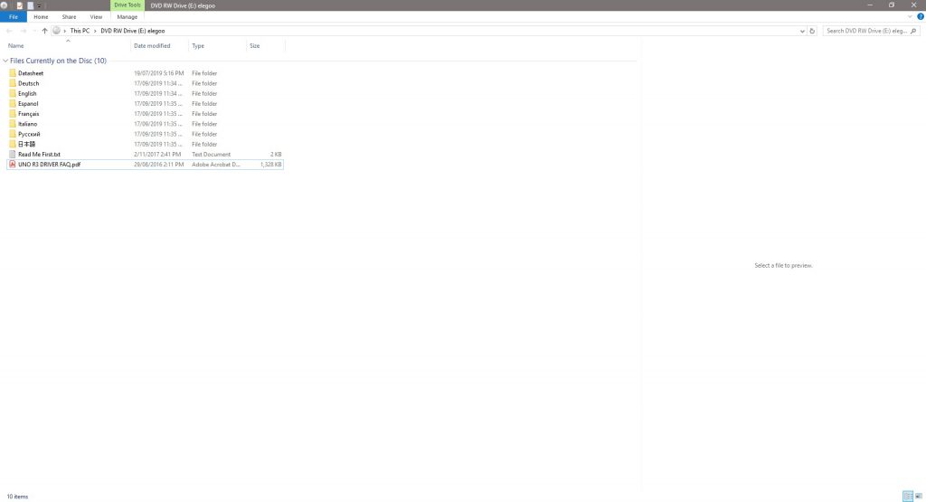
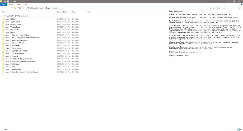
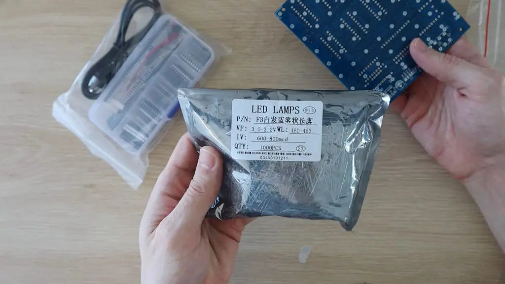
Included with the kit is a CD which contains a detailed tutorial guide as well as the code or sketches and the libraries used in the tutorials. We’ll have a look at this in more detail later on.
Let’s get the kit unpacked and see what’s included.
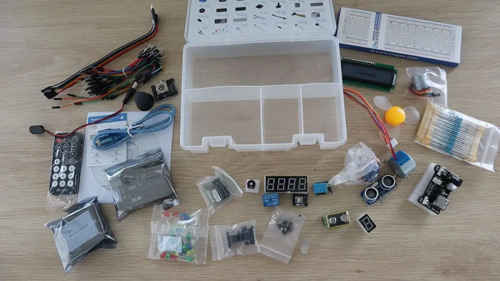
You’ve got a pretty good range of electronic components to get started with, here is what’s included in the Elegoo Uno Project Super Starter Kit:
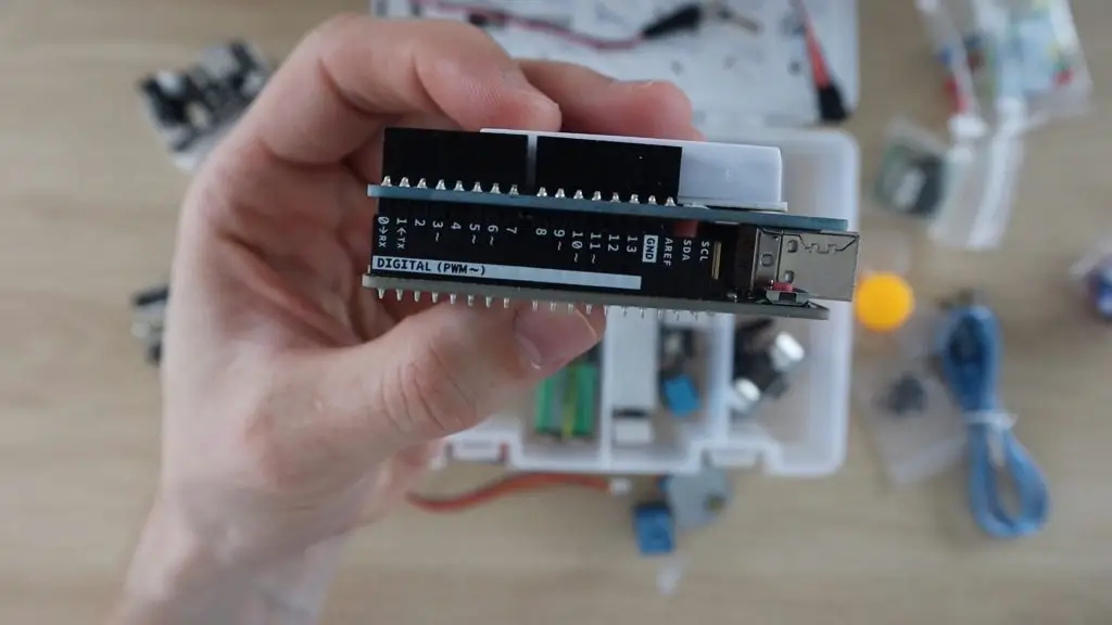
1pcs Elegoo Uno R3 Controller Board (Arduino-Compatible)
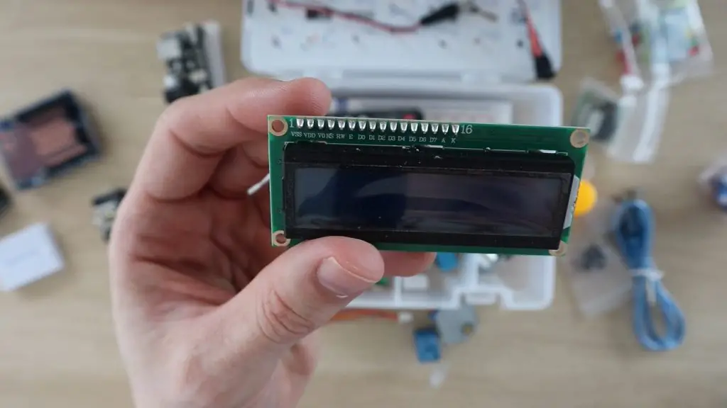
1pcs LCD1602 Module
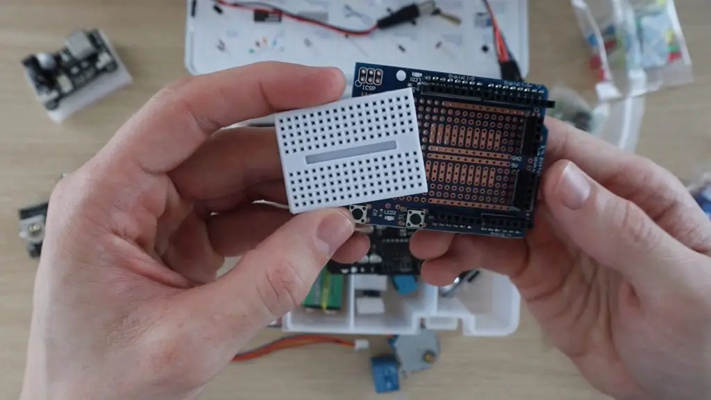
1pcs Prototype Shield With Mini Breadboard
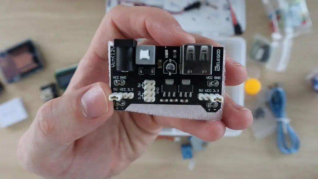
1pcs Power Supply Module
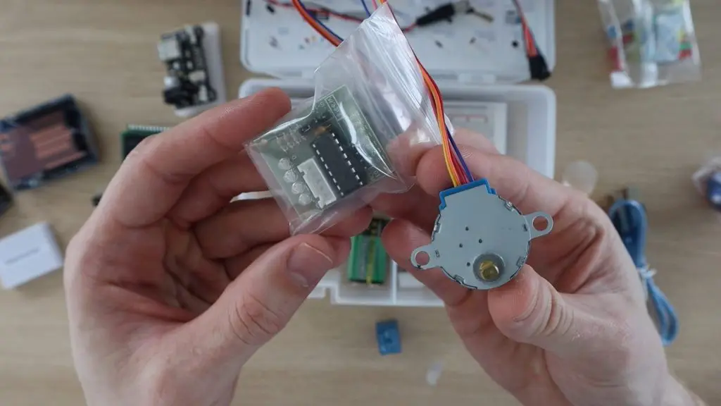
1pcs ULN2003 Stepper Motor Driver
1pcs Stepper Motor
1pcs Servo Motor (SG90)
1pcs 5V Relay
1pcs IR Receiver
1pcs Joystick Module
1pcs DHT11 Temperature and Humidity Module
1pcs Ultrasonic Sensor
1pcs DC Motor and Fan
1pcs Active Buzzer
1pcs Passive Buzzer
1pcs IC 74HC595
1pcs IC L293D
5pcs Push Button
1pcs Potentiometer
1pcs 1 digit 7-segment Display
1pcs 4 digit 7-segment Display
1pcs Tilt Switch
1pcs IR Remote
1pcs Breadboard
1pcs USB Cable
10pcs Female-to-male DuPont Wire
65pcs Breadboard Jumpers
1pcs 9V Battery
30pcs Various Resistors
5pcs Yellow LED
5pcs Blue LED
5pcs Green LED
5pcs Red LED
5pcs White LED
2pcs RGB LED
1pcs Thermistor
2pcs Diode Rectifier (1N4007)
2pcs Photoresistor
2pcs NPN Transistor (PN2222)
As with any starter kits, there are probably components that you’re interested in and some which you may never use, but you really can’t beat the value you get with a kit like this. You’d easily pay two to three times what this kit costs if you try and buy the components separately, so it’s a great way to start out.
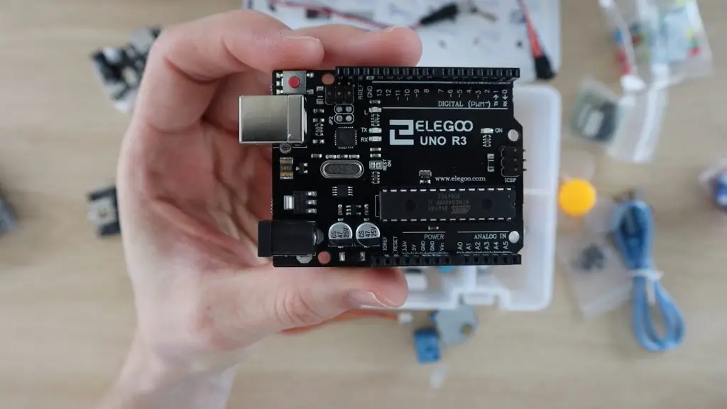
The Arduino you get with this kit is Elegoo’s copy of the Uno. It’s a great starter board, compatible with a wide range of shields and accessories, and is probably one of the most widely used as well. So you shouldn’t have any trouble trying out different projects and new sensors once you’ve worked through their tutorials.
They’ve included both a full-sized breadboard along with a prototype expansion shield with a mini breadboard on the top so that you can build more compact projects as well.
I do like that they’ve labelled the sides of the header pin strips with the port numbers. This is really useful if you’ve got a shield plugged in or you can’t see the top of the Arduino because it’s tucked into a tight case or container for a project.
Some other nice inclusions are a dedicated breadboard power supply with a 5V and 3.3V regulator, an LCD display and a stepper motor and driver.
Tutorial Guide & Included Code
Now let’s have a look at what is included on the CD with the Elegoo Uno Project Super Starter Kit.
As mentioned before, the CD contains a detailed tutorial guide as well as the code or sketches and the libraries used in the tutorials in a number of different languages.
This is quite useful as a few kits I’ve seen leave it up to you to find the libraries they’ve used, which can be a problem for new users. You can also download the contents of the CD along with up to date libraries through the Elegoo website, the download is around 250MB.
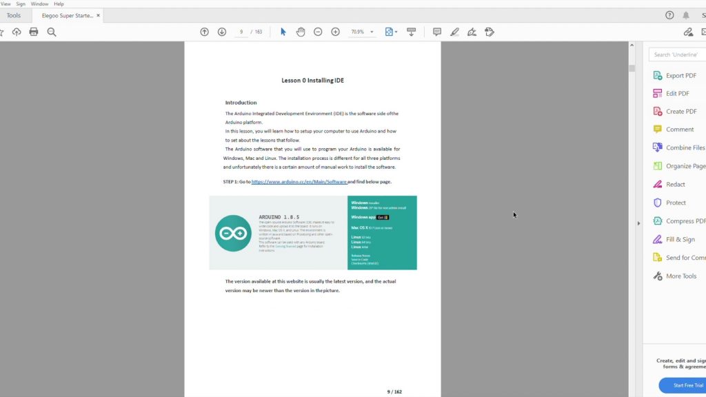
The tutorial guide starts out by explaining the Arduino IDE as well as how to connect and program your Arduino and how to install the included libraries.
They also detail how to install the drivers for the board. Both my Windows PC and mac picked the board up as an Arduino Uno right away and I didn’t need to install any additional drivers.
You’re then guided through 24 Lessons in total, which show you how to connect and program the Arduino to use all of the components supplied in the kit. Once you’ve worked through all of these, you should have a really good understanding of how any Arduino works and you’ll be able to build some pretty cool projects.
The lessons are quite details and tell you exactly what you need and how to connect them. They also give you a bit of background information for the components and give you a photograph of what the final setup should look like. You shouldn’t have any trouble getting each lesson up and running using the included components and the included sketches.
The only issue I could point out with the lessons is that they don’t go into much detail on how the code works. Some lessons have more details than others and they do point out any areas which you may get stuck or need to change for your specific project, but you probably won’t learn too much about the code if you don’t already have a basic understanding of the Arduino programming language or C++. But there is enough information to help you get by and get through each of the lessons.
Rather than go through one of the lessons which have already been done, I’ve put together two basic projects which use the included components and just combine sections of the included example code to make, so are really easy to get running.
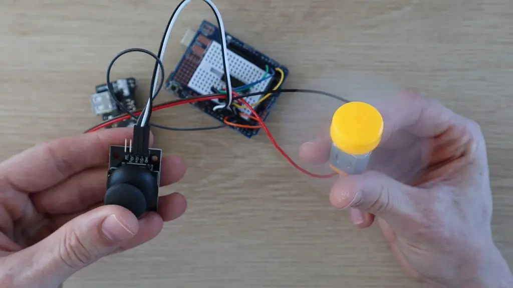
Sample Project 1 – DC Motor Throttle
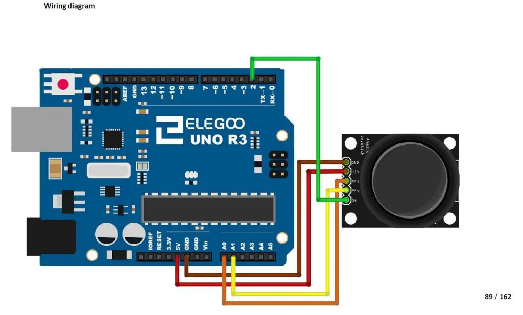
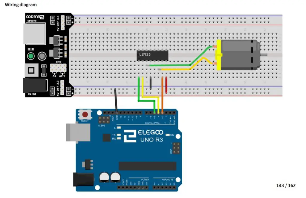
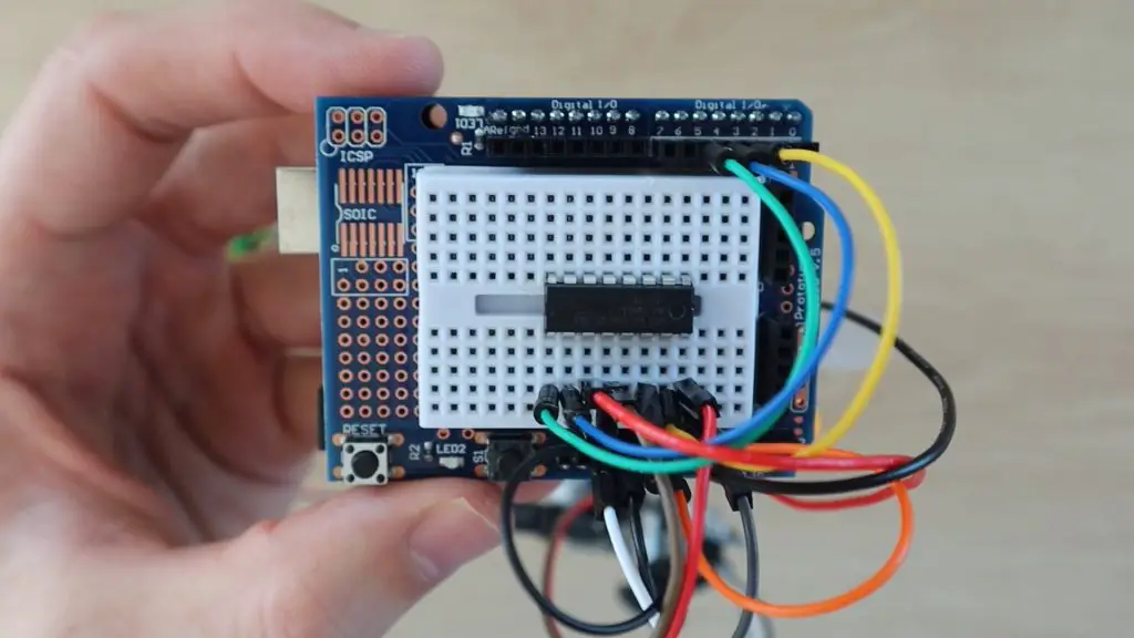
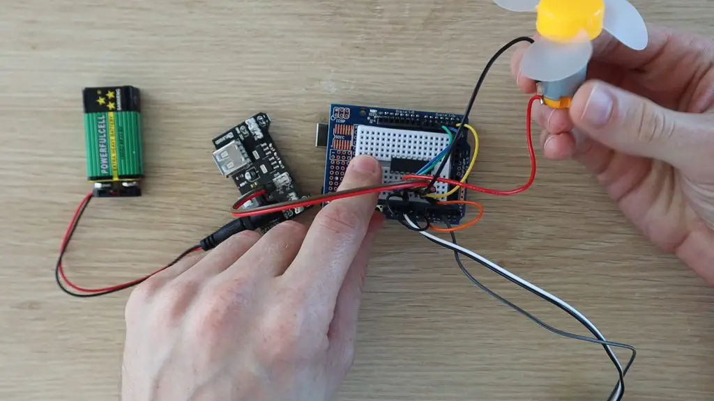
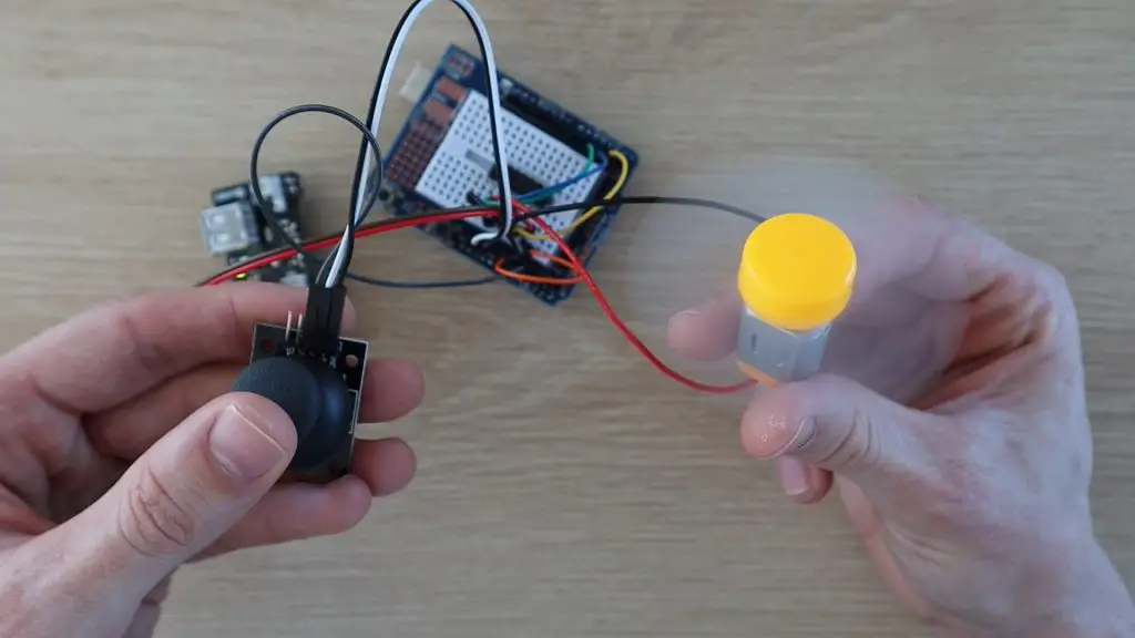
The first project I tried with the super starter kit is a simple throttle for the DC motor and fan. It uses one axis of the joystick to control the speed and direction of the motor using the included L293D motor driver chip. This project uses Lesson 12 for the analog joystick module input and Lesson 21 for the DC motor and driver. I assembled the components onto the prototyping shield and mini breadboard.
For this project, you’ll need:
Elegoo Uno R3
Prototyping Shield & Mini Breadboard
9V Battery & Lead
L293D Motor Driver
DC Motor & Fan
Joystick Module
Power Supply Module
Jumpers
I’ve connected the motor and driver as well as the analog joystick to the Arduino as outlined in the two Lessons in the tutorial.
For the joystick, we’ll only need one axis, I used the one to A1:
For the L293D DC Motor driver, I’ve used the circuit as shown, but with the mini breadboard. The power connections will need to be made directly onto the 5V header pins on the power supply module.
Once you’ve made the connections, your breadboard should look like this:
You’ll then need to program your Arduino.
I’ve also just copied sections of code from both lessons to make a really simple sketch to drive the motor.
//DC Motor Throttle Example Project

#define ENABLE 5                    //Define the motor driver pins
#define DIRA 3
#define DIRB 4

const int X_pin = A1;               //Define joystick input pin

int motSpeed = 512;                 //Variable to store the motor speed

void setup()
{
  pinMode(ENABLE,OUTPUT);           //Set the motor driver pin functions
  pinMode(DIRA,OUTPUT);
  pinMode(DIRB,OUTPUT);
}

void loop()
{
  motSpeed = analogRead(X_pin);                 //Read in the joystick position
  if (motSpeed>=532)
  {
    motSpeed = map(motSpeed,532,1023,0,255);    //Map the motor speed to the driver range
    analogWrite(ENABLE,motSpeed);               //Set motor speed
    digitalWrite(DIRA,HIGH);                    //Set motor direction
    digitalWrite(DIRB,LOW);
  }
  else if (motSpeed<=492)
  {
    motSpeed = map(motSpeed,492,0,0,255);       //Map the motor speed to the driver range
    analogWrite(ENABLE,motSpeed);               //Set motor speed
    digitalWrite(DIRA,LOW);                     //Set motor direction
    digitalWrite(DIRB,HIGH);
  }
}
I found the included battery to be a bit sluggish, for the motor, so I replaced it with a power supply to give it a bit more speed.
Push the joystick forward to drive the fan in one direction and backwards to reverse the fan.
The fan’s speed is also proportional to how far the joystick is pushed, so you can slow it down or speed it up in either direction. Have a look at the video at the beginning of this review to see some clips of the motor running.
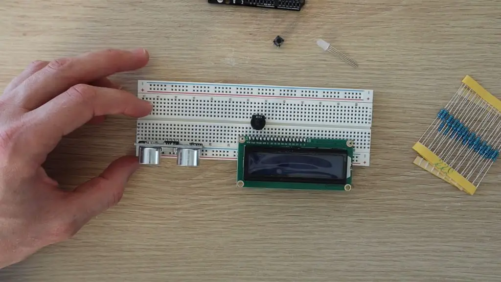
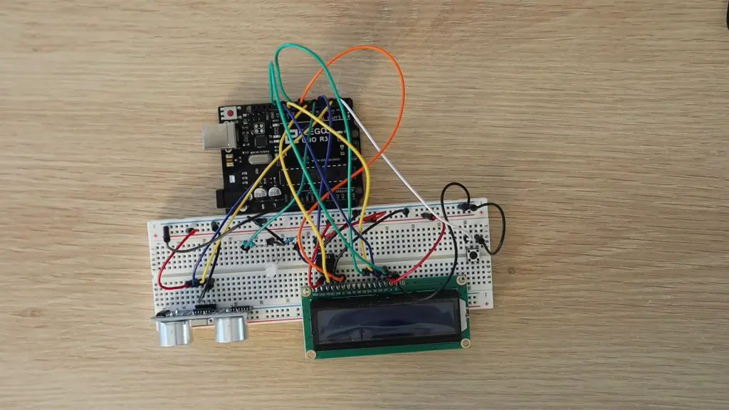
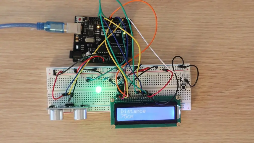
Sample Project 2 – Parking Assistant
The next project is a bit more complex, but all of the components and lessons used are included with the Elegoo Uno Project Super Starter Kit. It’s a parking assistant, which can be mounted onto a wall in front of your parking bay or garage to indicate when your car is in the right spot.
This parking assistant measures the distance to your car and guides you to park it in the correct spot using an LCD display readout and an LED, which progressively changes from green to red. The red LED starts flashing if you get too close. A button on the assistant lets you set a new parking position as well.
For this project, you’ll need:
Elegoo Uno R3
Breadboard & Jumpers
Ultrasonic Sensor
LCD Display
Tactile Pushbutton
5mm RGB LED
2 x 200ohm Resistors
10K Potentiometer
This project uses the following lessons from the tutorial:
Lesson 4 – RGB LED
Lesson 5 – Digital Inputs
Lesson 10 – Ultrasonic Sensor Module
Lesson 14 – LCD Display
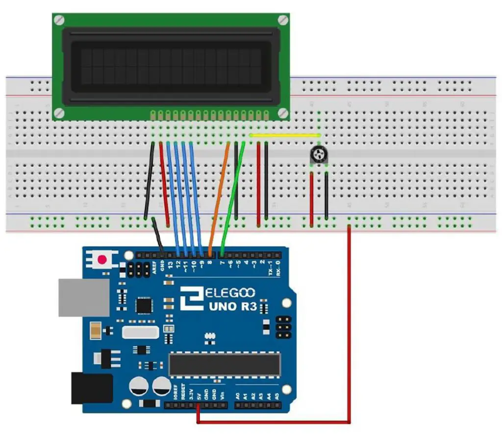
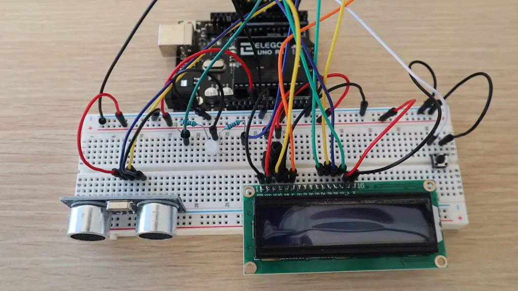
I’ve kept the connections for the LCD display the same as in the tutorial. The other components have been adjusted for the available IO.
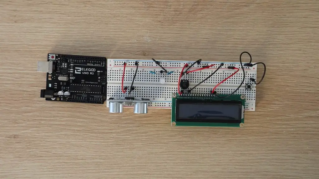
Start off by plugging your components into your breadboard. Try to separate them as much as possible, so that you’ve got lots of space to connect your jumpers.
There are three components which you should position in certain places to avoid additional jumpers:
Plug a 220ohm resistor onto a track connected to each of the positive (anode) legs of the LED. You’ll only need the red and green legs, you can leave the blue leg disconnected.
Plug the wiper (center leg) of the pot onto the same track as V0 on the LCD. This pot will be used to adjust the contrast of the LCD.
I’ve tried to keep this project as close to the example lessons in the Elegoo kit as possible so that it’s pretty easy to use the same connection diagrams and just copy and paste parts of the code to get it working.
Start off by connecting power to the components as shown in the below image, or follow the connections outlined in the lessons. You need a GND and 5V supply to the ultrasonic sensor, GND to the LED, GND to the pushbutton, and then a number of GND and 5V connections to the LCD and pot.
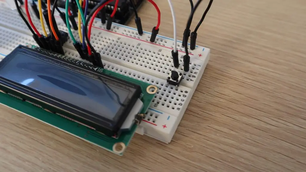
The connections to the LCD are done as per Lesson 14:
Once this is done, you can connect the remaining components to your Arduino’s IO:
Pushbutton – D2
Ultraonic Sensor Echo – D3
Ultrasonic Sensor Trigger – D4
RGB LED Green Leg – D5
RGB LED Red Leg – D6
LCD RS – D7
LCD EN – D8
LCD D4 – D9
LCD D5 – D10
LCD D6 – D11
LCD D7 – D12
Once you’ve made all of the connections, you can upload the sketch to your Arduino. This sketch has also been mostly constructed from parts of the four lessons, so it should be fairly easy to follow:
//Parking Assistant Example Project

#include "SR04.h"                             //Import Ultrasonic Sensor Library
#include <LiquidCrystal.h>                    //Import LCD Library

#define TRIG_PIN 4                            //Define sensor pins
#define ECHO_PIN 3

SR04 sr04 = SR04(ECHO_PIN,TRIG_PIN);          //Create sensor object
LiquidCrystal lcd(7, 8, 9, 10, 11, 12);       //Create LCD object

int greenLedPin = 5;                          //Define IO pins
int redLedPin = 6;
int buttonPin = 2;

int maxDist = 80;                             //Define parking assistant parameters
long dist;
long parkDist = 20;

void setup()
{
  lcd.begin(16, 2);                           //Start the display and display startup text
  lcd.print("Parking");
  lcd.setCursor(0,1);
  lcd.print("Assistant");
  pinMode(greenLedPin, OUTPUT);               //Define IO pin functions
  pinMode(redLedPin, OUTPUT);
  pinMode(buttonPin, INPUT_PULLUP);
  delay(2000);
  lcd.clear();                                //Clear the startup text
}

void loop()
{
  boolean tooClose = false;
  dist = sr04.Distance();                                       //Measure the distance to an object
  lcd.print("Distance");                                        //Display the measurement
  lcd.setCursor(0,1);
  lcd.print(dist);
  lcd.print("cm");
  if(dist >= maxDist)                                           //Define the parking distance limits for the LED
    dist = maxDist;
  else if(dist <= parkDist)
  {
    dist = parkDist;
    tooClose = true;
  }
  analogWrite(greenLedPin, map(dist,parkDist,maxDist,0,255));   //Display the object distance on the RGB LED
  analogWrite(redLedPin, map(dist,parkDist,maxDist,255,0));
  if (tooClose)
  {
    digitalWrite(redLedPin, HIGH);
    delay(250);
    digitalWrite(redLedPin, LOW);
    delay(250);
  }
  if (digitalRead(buttonPin) == LOW)                            //Set the new parking distance if the button is pushed
  {
    parkDist = dist;
    digitalWrite(greenLedPin, HIGH);                            //Flash LED to indicate new distance has been set
    delay(500);
    digitalWrite(greenLedPin, LOW);
    digitalWrite(redLedPin, HIGH);
    delay(500);
    digitalWrite(redLedPin, LOW);
  }
  delay(500);
  lcd.clear();                                                  //Clear the display
}
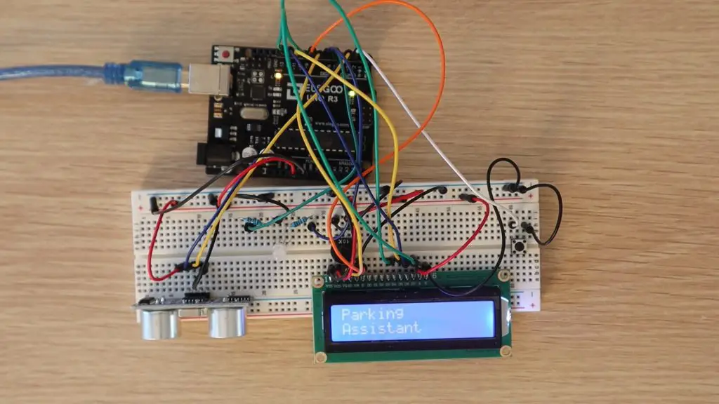
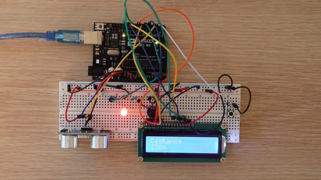
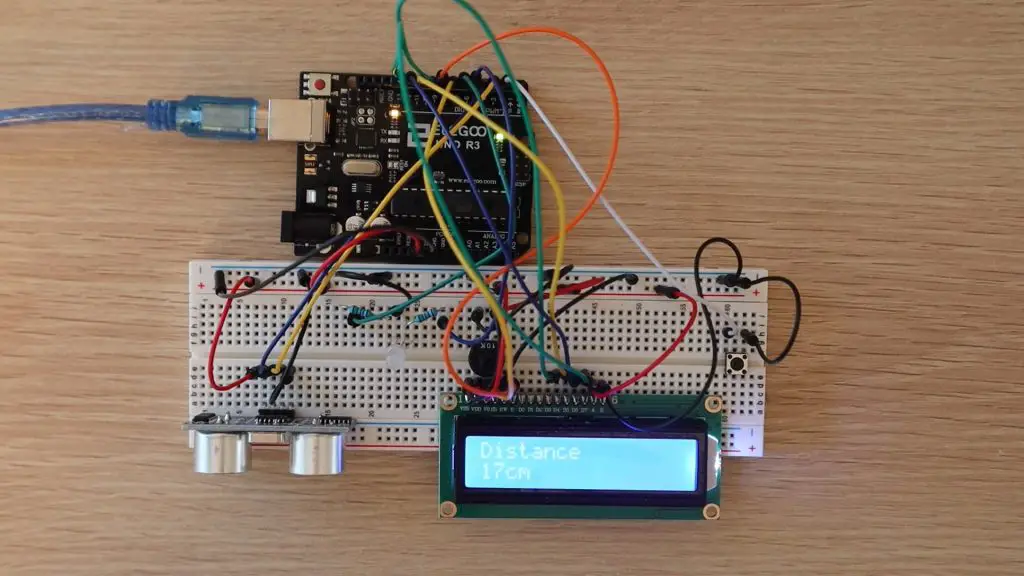
When you power the parking assistant up, it shows a brief Parking Assistant splash screen and then starts taking distance measurements to the object in front of the ultrasonic sensor, to a maximum of 80cm – this can be changed in the code to suit your parking spot/garage.
The distance is displayed on the LCD and the RGB LED will light up according to the distance to the object. If the object is at the maximum distance, the LED will be completely green and if it is at the minimum distance (the correct parking spot) then it will be completely red.
The LED will change colour proportionally in between these two limits, with a yellow colour in the middle. If the object comes closer than the minimum distance, the LED will flash red.
The LCD will continue to display the actual measured distance while the LED is flashing.
Trying moving your body or hand in front of the ultrasonic sensor and check that the measurements on the LCD change and that the RGB LED changes from green when you’re far away to red when you’re close by. Have a look at the video at the beginning of the review to see some clips of the parking assistant in operation.
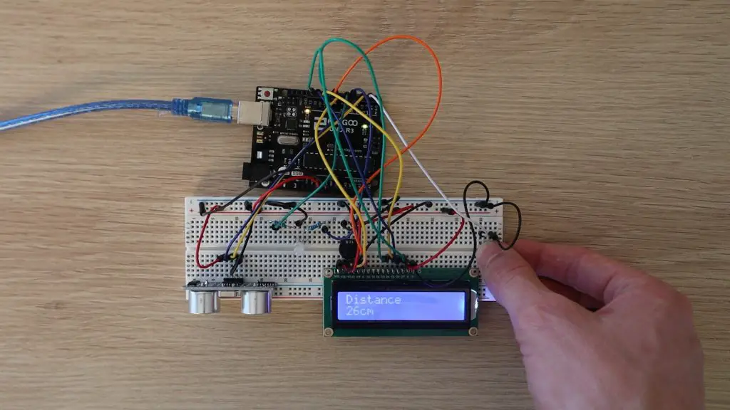
To set a new parking position, make sure that the car is parked in the new position to be set and that the display is showing the correct distance to the car, then push the button to update the parking position. Note that this doesn’t change the maximum distance, so if you need to park your car further than this distance, then you’ll need to update this in the code, this adjustment is meant to be used for fine adjustment.
Try placing an object or your hand at a certain distance, say around 40cm from the ultrasonic sensor and push the button. The LED should flash green and then red and the new distance will then be set. You should now notice that the RGB LED turns completely red by 40cm instead of 20cm and starts flashing when the distance is less than 40cm.
To reset the distance, set the object to 20cm from the sensor and press the button again.
The correct spot being 20cm and the maximum distance being 80cm are just arbitrary numbers used for this example. You’ll need to set up your own limits for your own garage and car before you use it.
That’s it, your parking assistant can now be installed into an enclosure and mounted onto the wall in your garage. You might also want to position the LCD and LED a bit further up the wall than the ultrasonic sensor so that it’s easier to see.
Conclusion
Overall I think this is a great value kit and an excellent way to get started tinkering with Arduinos and electronics. There’s a good selection of components and unlike some other starter kits, Elegoo includes loads of jumpers, resistors and LEDs for more complex projects.
If you’re interested in buying one of these kits, head over to Amazon to pick one up. Elegoo have given me a discount code to share with you too, use the code DWZRAUL5 to get a discount on the kit from their Amazon store until 27/09/2020 11:59 PM AEST
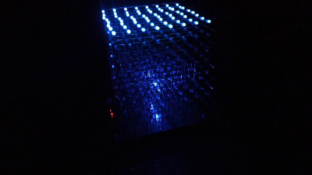
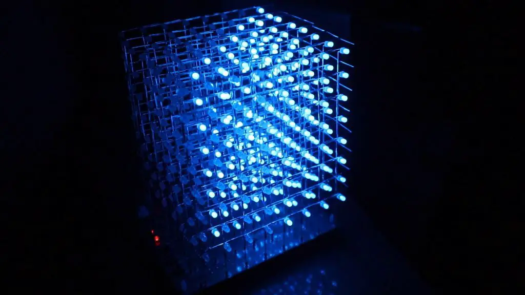
I bought this kit a while ago when I was looking at building an Arduino based 8x8x8 LED cube. This one was listed on Amazon as Arduino compatible, meaning that I should be able to re-program it using the Arduino IDE after assembling it to display what I want.
The kit was delivered quite quickly, but there was one pretty obvious thing missing, the assembly manual. I had a look on the product page on Amazon, emailed the supplier, and Googled the supplier and other 8x8x8 cube kits to try and find the manual. The supplier never got back to me and although I found a few similar cubes, I never found an assembly manual for this particular cube, so I packed the kit away and forgot about it for a few months.
A week ago, I found the kit again and decided to try assembling it. At worst, I’d have a cube that didn’t work and would just be a dead shelf decoration.
Here’s a video of the build and the 8x8x8 LED cube working, read on for the detailed assembly.
Buy Your Own 8x8x8 LED Cube Kit
8x8x8 LED Cube Kit (Like The One In The Video, Probably Has No Instructions Either) – Buy Here
8x8x8 LED Cube Kit (Better Quality, Not Arduino Compatible) – Buy Here
Assembling The 8x8x8 LED Cube
So let’s get started with putting the cube together.
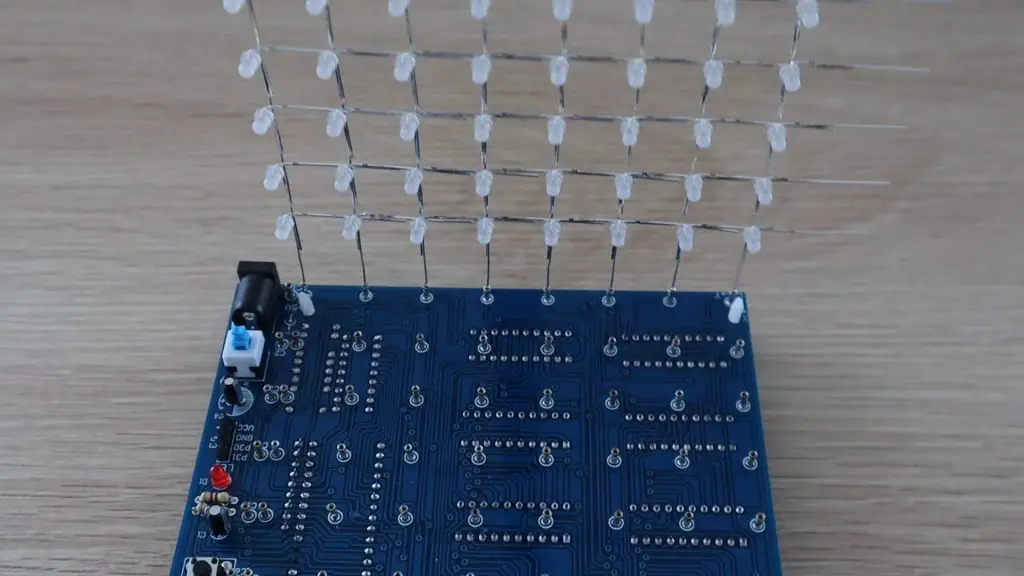
The kit arrived quite quickly and this is what was delivered.
There was a bag of LEDs, they said that 550 LEDs are supplied in case some are faulty, the PCB to mount the components, and then a small case with the chips and other electronic components.
The product page said that the cube was Arduino compatible, although the chip supplied is a STC12C5A60S2 micro-controller. You’ll need a USB-2-TTL programming module to re-flash this micro-controller. There is guide a good guide and software to re-programming the STC micro-controller on GitHub.
Soldering The LED Layers
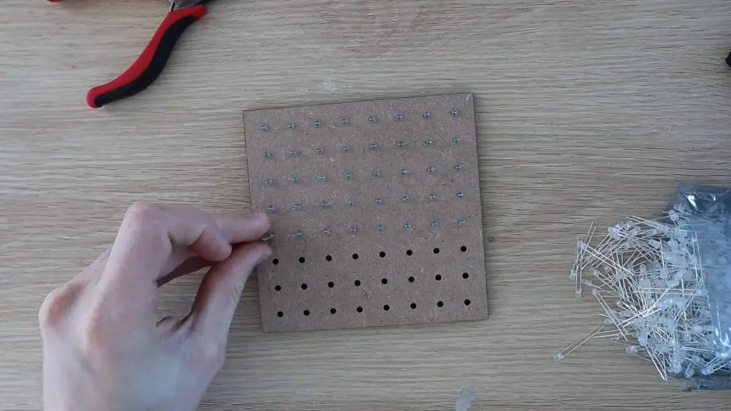
I started out by testing all of the LEDs. I’ve never found a new LED to be dead, but since they said that they included 550 LEDs in case some were faulty, I decided to test them all first to avoid have to replace LEDs once it was all assembled. I set up a simple 5V power supply and 220 ohm resistor on a breadboard and got testing.
I didn’t find any faulty LEDs, but I still think it was worthwhile to save the frustration if I had.
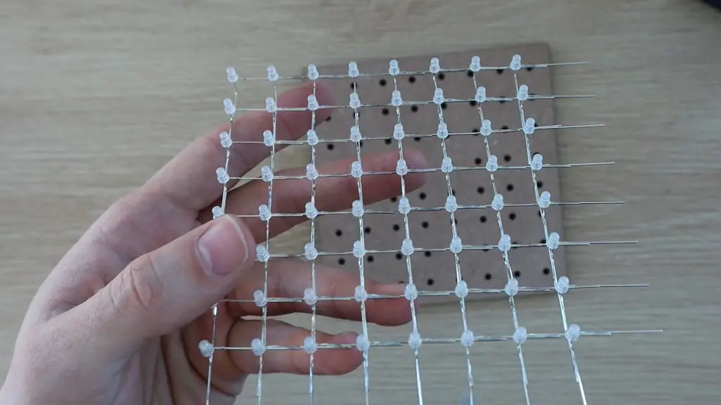
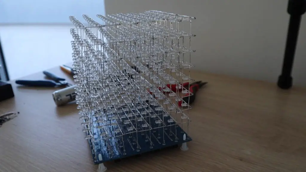
Next, I laser cut a template to lay out the LEDs. Rather than trying to get the placing right for each individual LEDs, having an MDF board which I could press the LEDs into and then connect up while they’re held in place would dramatically speed up the process and hopefully result in nice straight and evenly spaced grids of LEDs.
I cut two layers, one with 3mm holes to hold the LEDs and one with 5mm holes to be the bottom spacer layer so that the LEDs don’t touch the table underneath them when they’re pushed into the template.
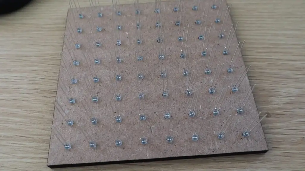
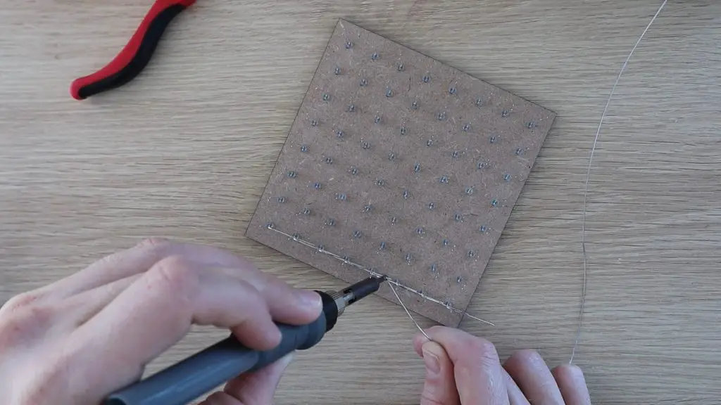
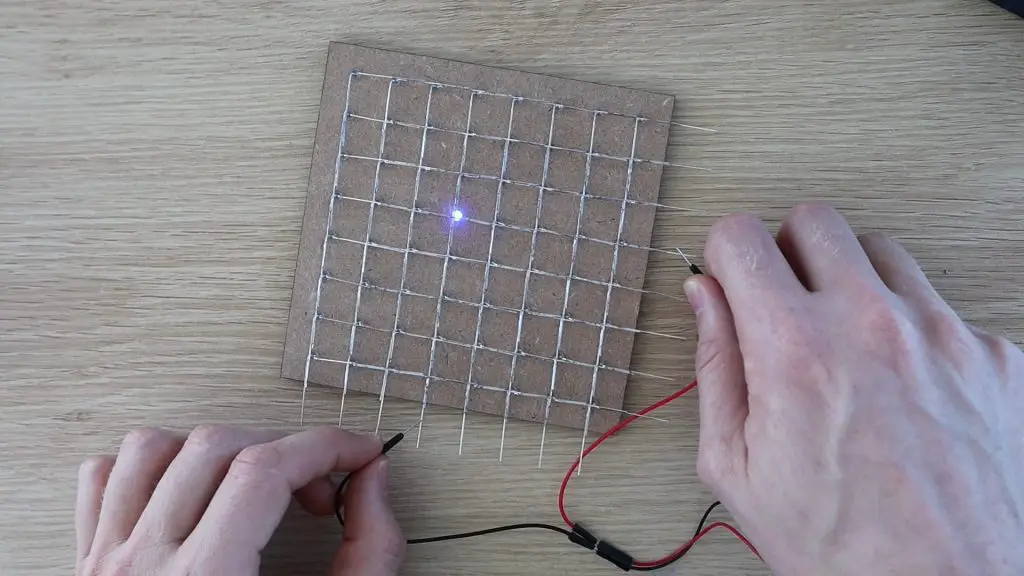
I then layed out the 64 LEDs on the template, making sure that the LEDs were all facing the same direction.
So with the longer positive leg or anode on the right side and the negative leg, or cathode on the left side.
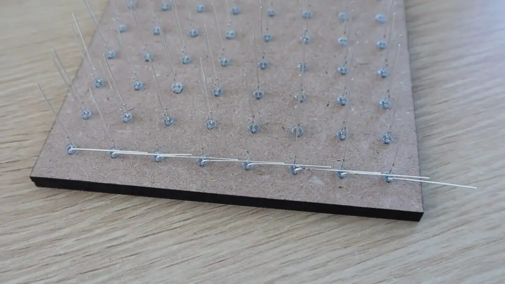
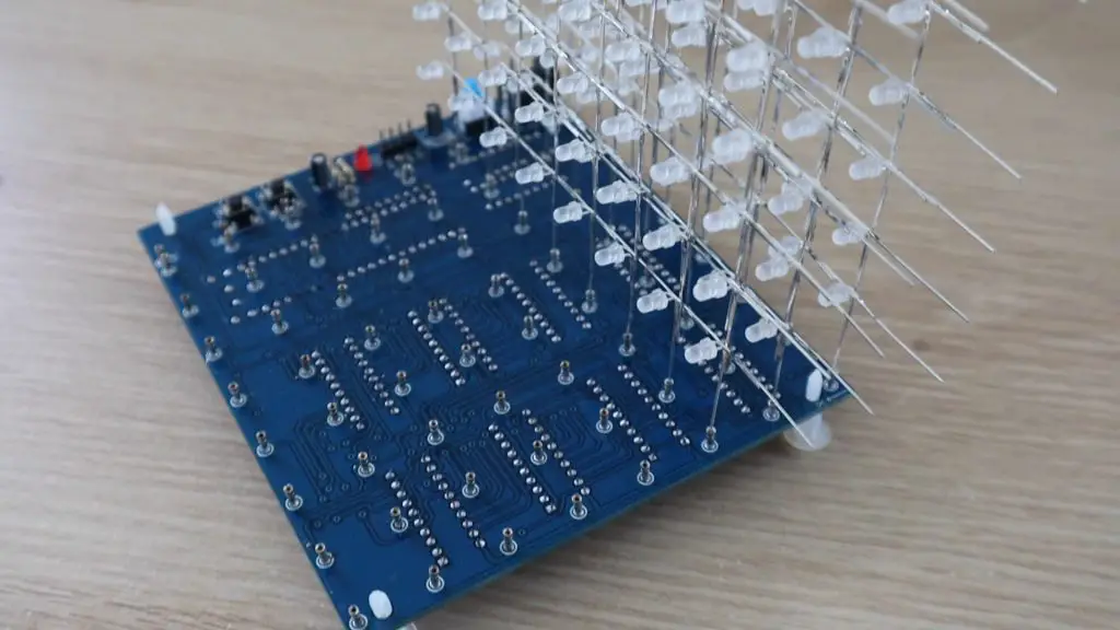
Next, the idea is to connect all of the positive legs together in each column and all of the negative legs together in each row, making sure that they don’t touch each other. I started with the negatives, bending them all down so that there was some overlap between them.
I then soldered them together.
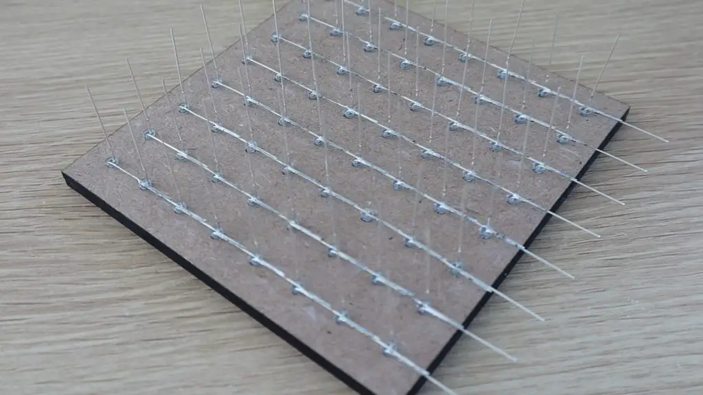
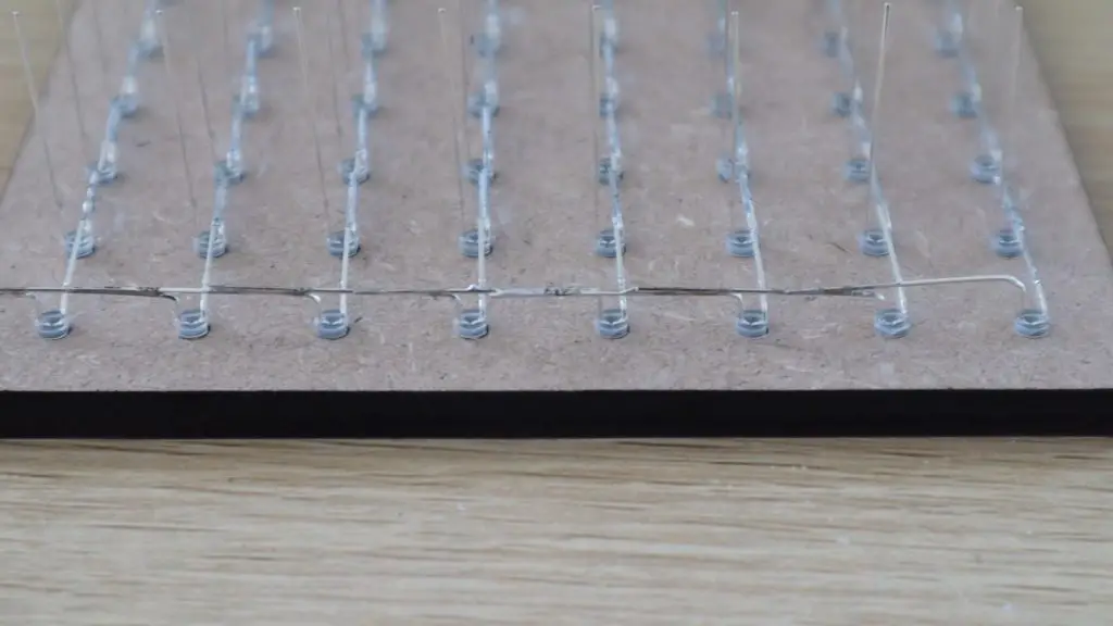
Once all of the negatives were done, I did the positives. I used a pair of pliers to space the bend a little away from the back of the LED so that the positive connections were spaced about a millimeters away from the negative connections. In hindsight, these legs should have been bent in the opposite direction in order to keep the connections on the back side of the cube when it’s on display, but this isn’t particularly noticeable in the end.
I continued this until all of the columns and rows on this layer were connected.
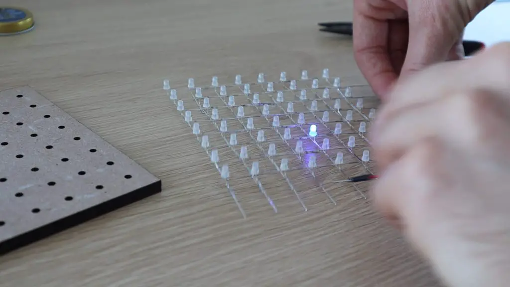
I then tested the LEDs again, this time testing the soldered connections. I used a small battery pack for this and just ran the leads over the columns and rows, checking that each LED lit up. I was glad I did this as I found two bad connections on my first layer.
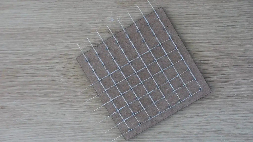
I then carefully removed the layer of LEDs from the template, trying not to bend the legs of the LEDs.
I was worried that I might have damaged some of the joints when removing the LEDs, so I tested this layer again once I removed it from the template.
I tested the subsequent layers only after removing them from the template. The next few went a lot better, but I did still find one or two bad connections, and one LED installed the wrong way around.
Creating these layers is the most time-consuming part of the build, but time spent here will result in a much neater looking cube down the line. It’s also definitely worth taking the extra minute or two between layers to test all of the connections. Even fixing a single bad joint once the cube is assembled will be near impossible without damaging it when taking it apart again.
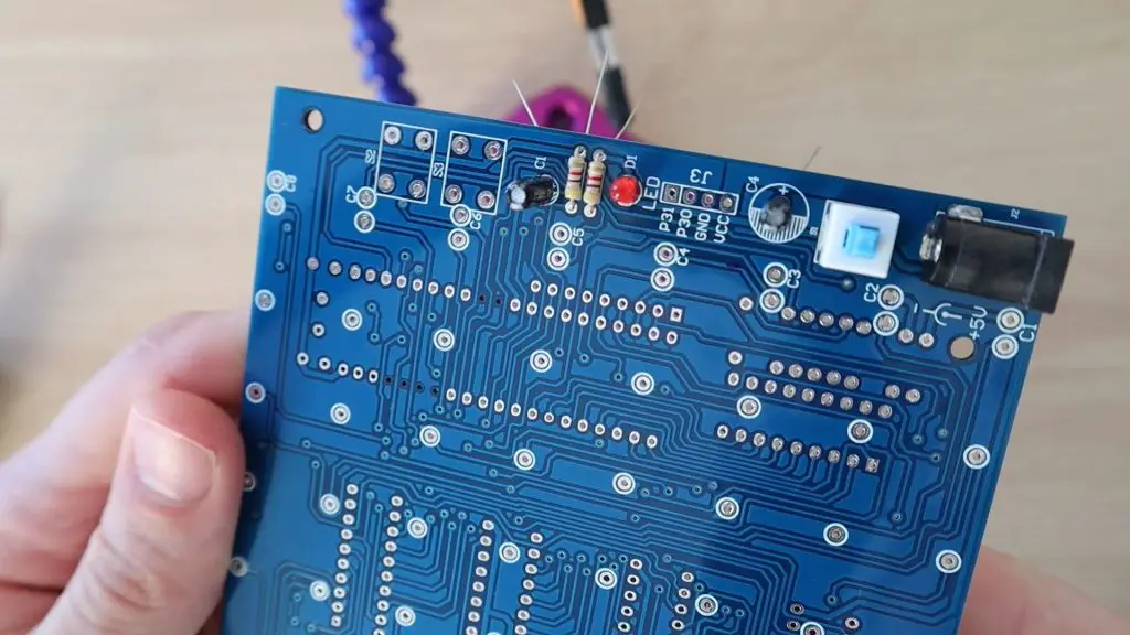
Soldering The PCB Components
Once all of the layers of LEDs were made, I got started with soldering the components into place.
This was where some guesswork came in. It was pretty obvious when making the layers that the LEDs had to be connected in a particular way, but it’s less obvious which capacitors and resistors go in which places on the PCB when it isn’t labeled.
The two electrolytic capacitors were the same value, despite the markings on the PCB being different sizes, so I just installed those in the two available spots. The ceramic capacitors were all the same size, although there were three supplied and only two spots on the PCB for them. I also noticed that there were two different value resistors supplied, 2 of one resistance and 8 of another. I noticed that the PCB had two resistors on one side and 8 on the other, so I decided to install them with two of the same on one side and the 8 others on the other side and hope for the best.
There are three different size chips. The ones that are the same size are all the same, so those are quite easy to figure out and the remaining components could be figured out based on the PCB holes.
The final part of the PCB assembly is to mount these LED leg holders onto the board to plug the LEDs into. I cut the strips up into individual pins and then broke the plastic off of them. I then installed one on each of the holes on the PCB. Luckily these could be installed from the component side of the PCB as the back side of some of these pins were covered by the IC sockets, something which I hadn’t thought about earlier.
I also noticed that on the PCB there are laocations for some header pins and two pushbuttons, but the components weren’t supplied. I assumed that the header pins are for programming the chip and the pushbuttons could be used to change the display currently being run on the cube, but this probably wasn’t preloaded onto the chip either. I decided to install these components as I had some pushbuttons and pins lying around and I wanted to be able to re-program the chip later as well.
Assembling The Cube Layers
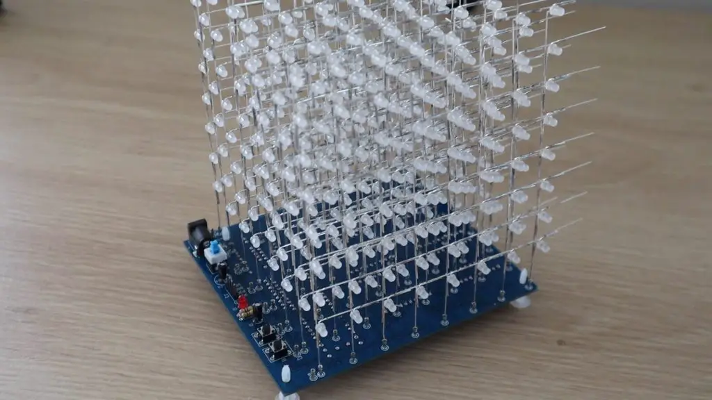
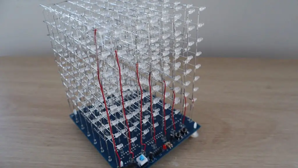
Now that the components are all in place, I could plug the LED layers in.
From other cubes I’ve seen online, I assumed that the positive legs of the LEDs went into the holes directly underneath the cube for the columns and that the negative legs would get joined in layers and connected to the holders alongside the cube. It turned out that the negative legs on my LED layers should have been on the other side, as that was the back side of the cube, but this doesn’t really make much difference.
First LED layer in place.
I then installed them remaining LED layers.
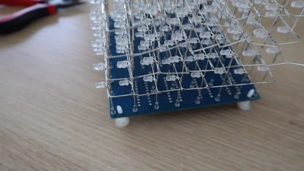
Once the layers were installed, I bent the negative legs at 90 degrees to join each layer together and soldered them together.
The next mystery was to decide which layer to connect to which numbered holder. I wasn’t sure if pin 8 was to go to the bottom layer or top layer? One diagram in another cube’s manual had the layers labelled with 1 being the top layer and the image alongside clearly showing the bottom layer being wired to 1.
I decided to temporarily connect these are there was a good chance my guess would be wrong.
Another issue was that the red insulated wire supplied to connect the layers to the holders was too short by 2-3cm. I didn’t waste any of it with incorrect lengths or stripping too much wire, so I’m not sure why it was too short. I made a plan for the shortest connection and was then ready to power up the cube.
Powering Up the Cube
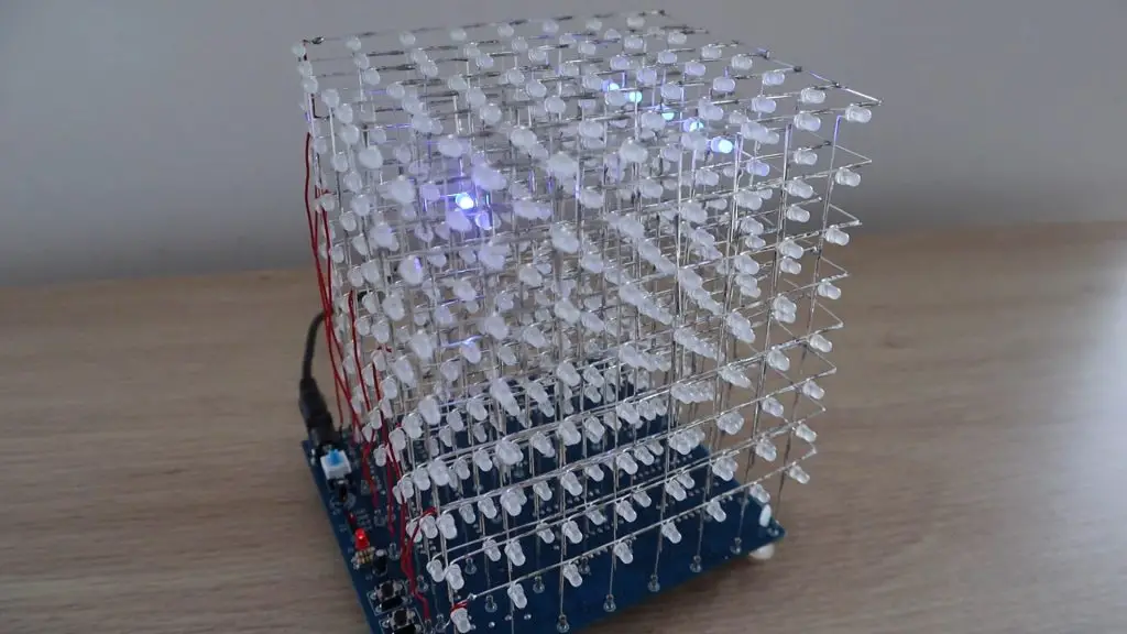
I plugged the power supply into a USB charger and pushed the switch to turn it on.
The built-in program is a bit odd in the beginning and its not really clear if the of the layers are working or not working correctly. I would have thought that a good initial test would be to light up all LEDs or at least the layers sequentially.
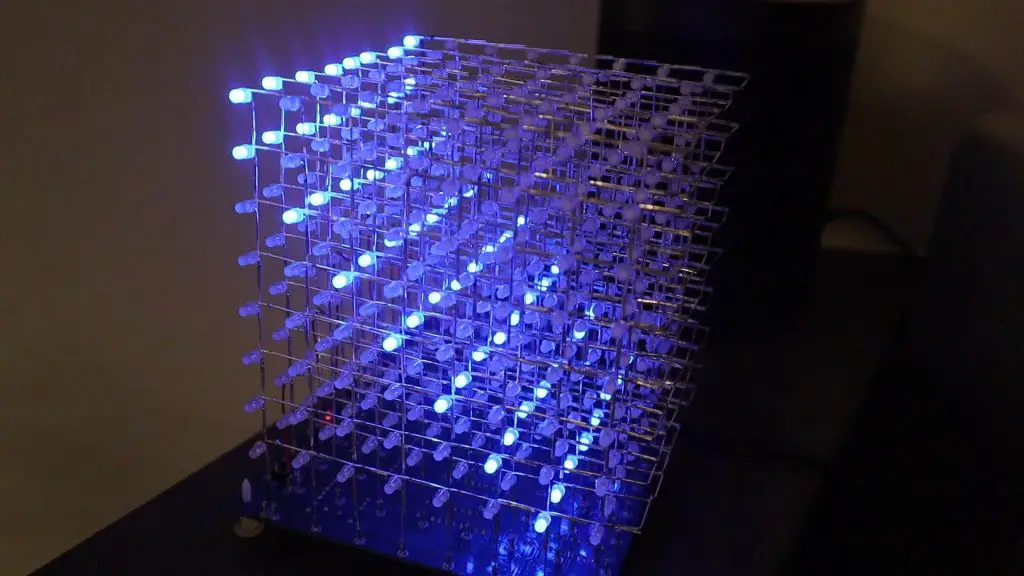
I left it running and eventually some recognizable patterns started emerging and it looked like I had guessed the layers correctly. There was a typical “rain” type animation where the LEDs drop from the lit-up top layer, and the top layer was actually at the top of the cube, so I assume that I’ve got the layer numbers correct. If they were the wrong way around then the rain would fall upwards.
As expected, the buttons don’t seem to do anything, but I’ll be looking to program them to change what is being displayed on the cube once I figure out how to program it. It also seems like the resistors are correctly installed, there aren’t any obvious bright or dim rows or columns.
Next I’m going to try and figure out how to program it and I’ll be making a clear acrylic case for it as well.
Have you tried building your own 8x8x8 LED Cube? How did it go and did you build it from scratch or use a kit? Let me know in the comments section below.
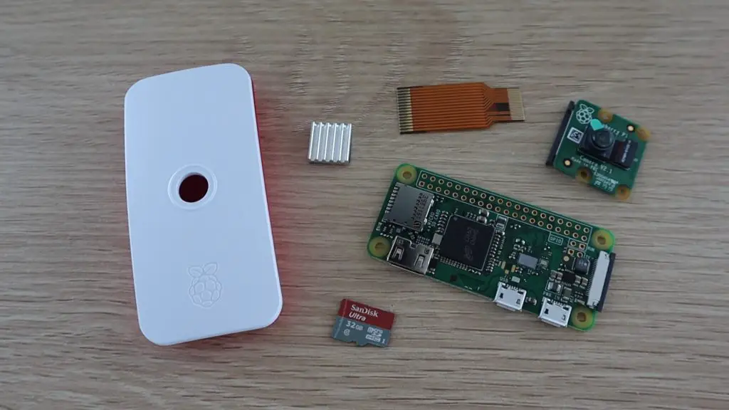
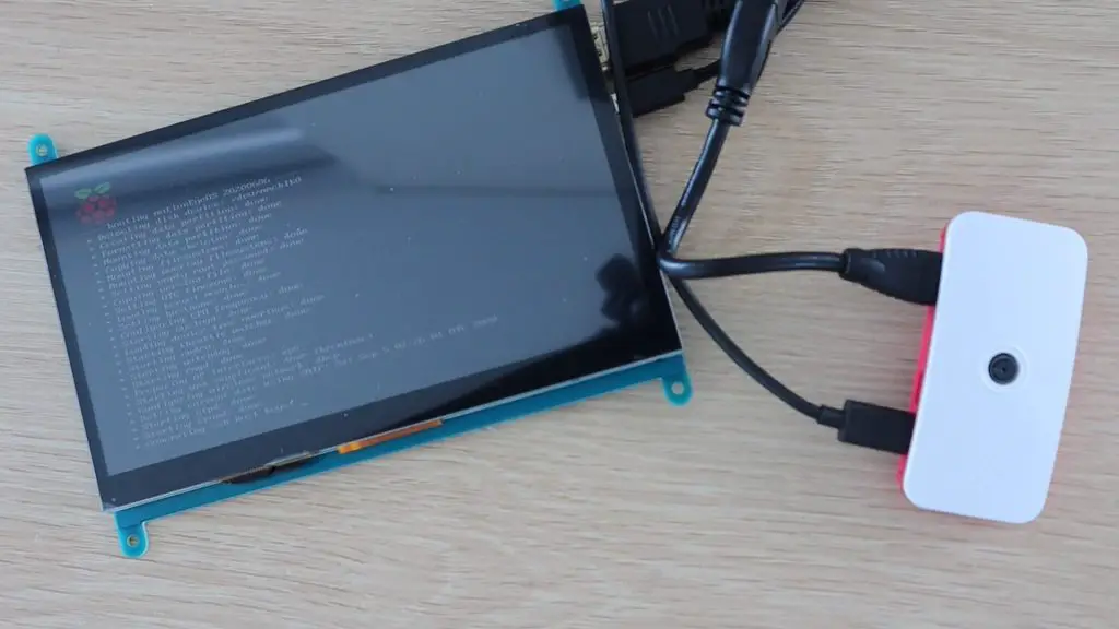
In this project, I’ll be showing you how to assemble and configure a Raspberry Pi Zero W to be used as a WiFi security camera, which is also accessible over the internet.
We’ll be using an operating system called MotionEyeOS on the Raspberry Pi, which is a web-based, mobile and tablet friendly surveillance system. It can be used with both the Raspberry Pi camera or any USB web camera plugged into the Raspberry Pi. You can also set up motion detection with email notifications, take still images and time-lapse movies, and even configure it to upload media files to network storage locations or to cloud storage services.
Here’s a video of the build and the camera in operation, read on for the full step by step instructions.
Optional Alternative (You’ll still need to buy the camera):
Pi Zero W Kit (Includes Pi Zero W, Case, SD Card, Power Supply & Camera Ribbon Cable) – Buy Here
Assembling The Raspberry Pi Zero WiFi Security Camera
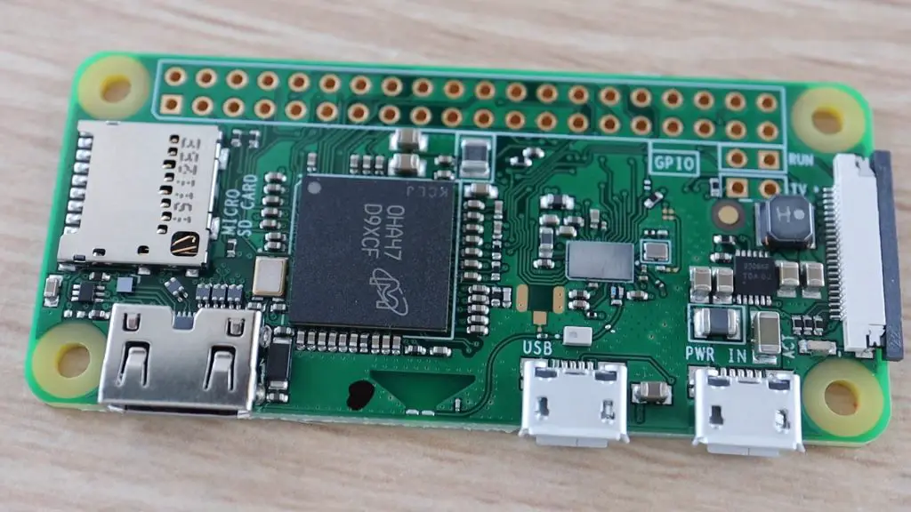
I’ve used a Raspberry Pi Zero W for this project because they’re relatively cheap and compact, making them perfect to mount discretely around your home. You can set up a couple of cameras around your home for less than $100. The W version has built-in WiFi, so there’s no need for an external WiFi or Ethernet adaptor to connect it to your home network.
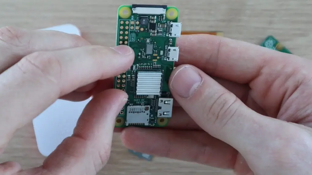
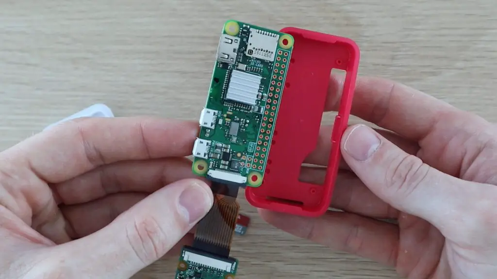
Let’s start by assembling the components into the Raspberry Pi Zero case.
If your Pi Zero came with a heat-sink, attach it to the board using the adhesive tape on the heat-sink.
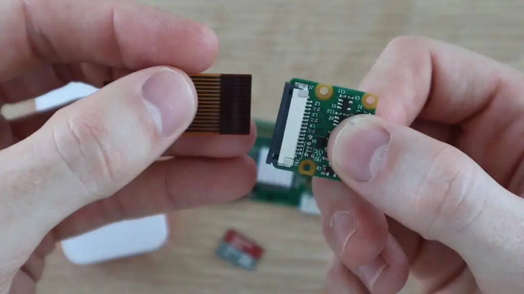
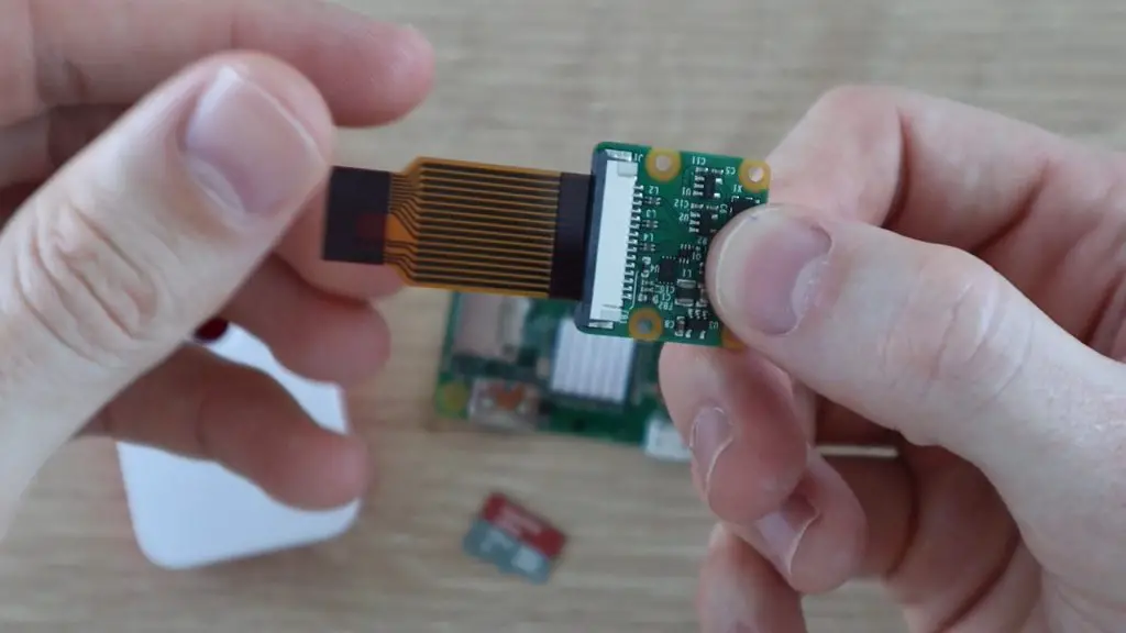
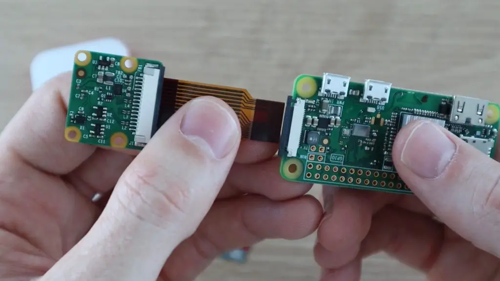
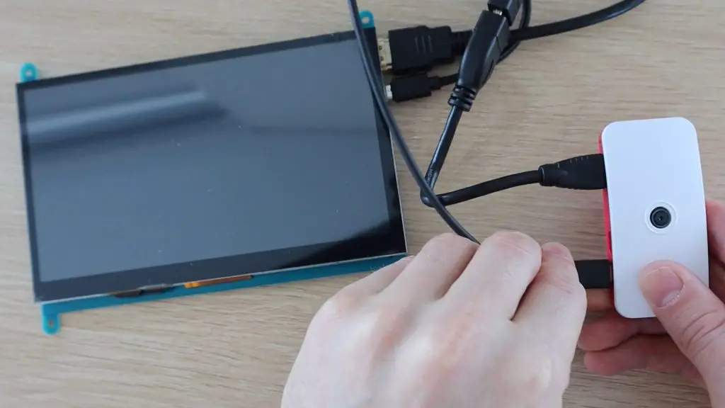
Once you’ve done that, you’ll need to connect the camera to the Pi.
The ribbon cable just slides into the connector with the contacts facing towards the board.
Make sure that the black clip is pulled away from the connector to open it. Then push the black clip back into place to grip the ribbon cable once it is seated correctly in the connector.
Now do the same on the connector on the Raspberry Pi to connect the camera module to the Pi.
Next open up the case and push the Pi into the back of the case. There are small pegs on the case which align with the screw holes on the Pi and the ports should all be aligned with the cutouts on the side of the case.
Next, clip the camera into place on the top cover and then close up the case to check that it all fits correctly.
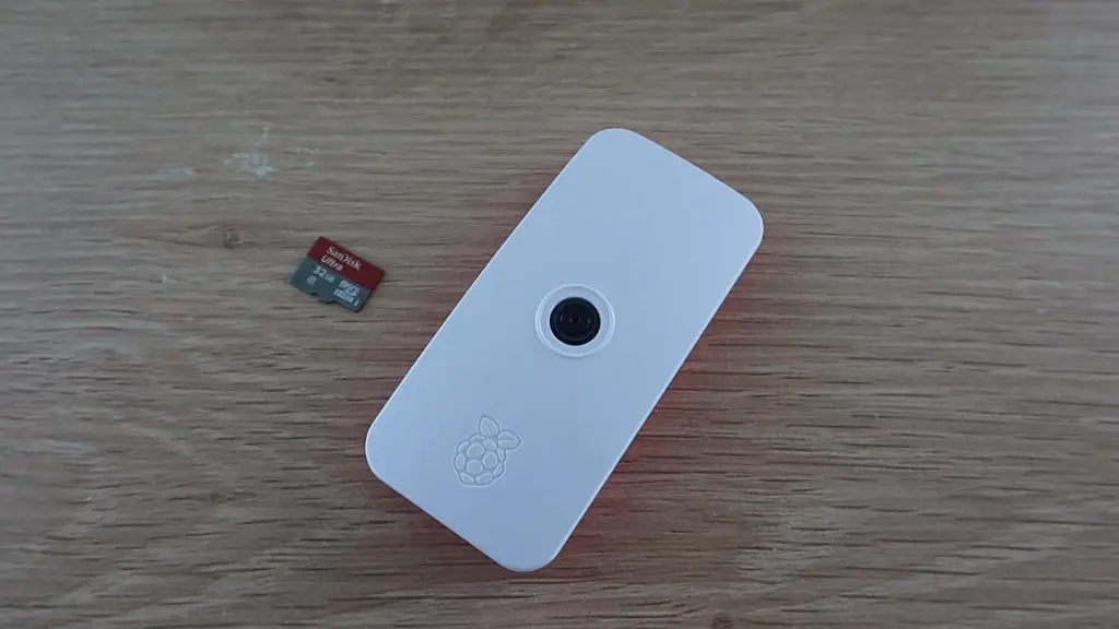
We can now move on to preparing the SD card with the MotionEyeOS operating system.
Loading The Operating System Onto The SD Card
Use a card reader to plug the card into your computer.
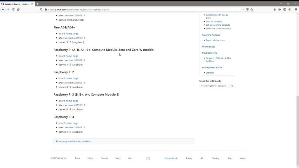
If you’re not using a Raspberry Pi Zero, or you’d like to use a different board, have a look at the list of Supported Devices to see which version of the operating system you should download.
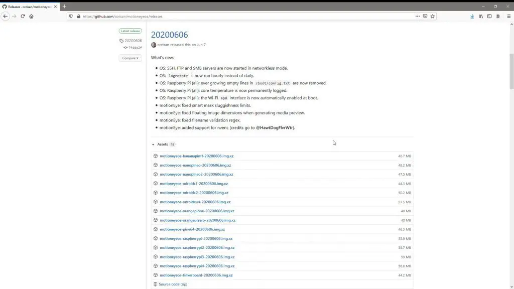
Go to the list of latest releases and make sure that you download the latest version of the software which is compatible with your board.
We’ll be using the Raspberry Pi version which was released on the 6th of June.
Once you’ve downloaded the software, you’ll need to unzip it to a folder on your computer. I used Easy 7-Zip for this. Don’t try to flash the zipped image to your SD card, it won’t work.
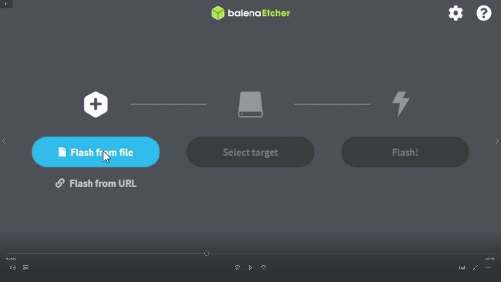
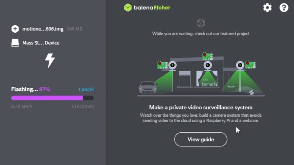
You’ll then need to use an image flasher to flash the disk image to your SD card. The one recommended in the installation instructions on GitHub is Balena Etcher. Once you’ve downloaded and installed the software, you can flash the disk image.
You’ll need to first select the source file, which is the disk image that you unzipped in the previous step.
Then select your destination target, which is your SD card.
Then click on Flash and wait for the software to write the disk image to your SD card.
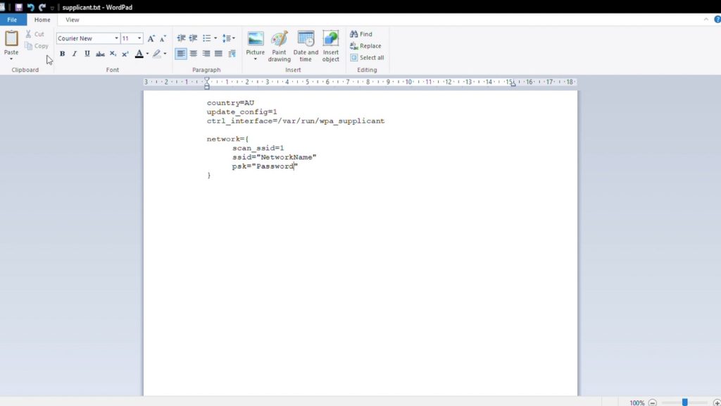
Finally, you’ll need to tell your Raspberry Pi how to connect to your WiFi network.
To do this, use the template below. It’s a basic text file in which you’ll need to add your country code and then your Network name or ID and the network password.
Rename the file to wpa_supplicant.conf, making sure to change the extension as well and then put it into the 30MB settings partition which you’re able to write to on your SD card.
Once you’ve done this, your SD card is ready to be installed into your Pi for the first boot up.
Booting & Configuring Your Pi Zero Security Camera
You don’t need to attach a monitor for this next step, but it is helpful to check that you don’t get any error messages and to make sure that the Pi has finished booting up.
The first boot up takes about a minute or two to complete, it’ll boot up much faster than this after the first boot.
If you haven’t used a monitor then you’ll need to find the IP address of the Pi using a network analysing tool on your computer.
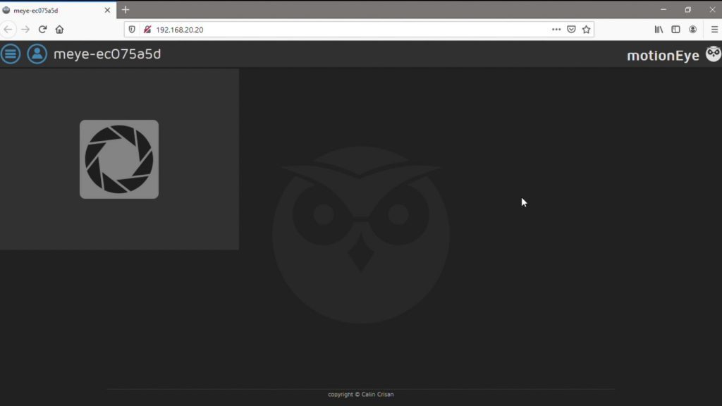
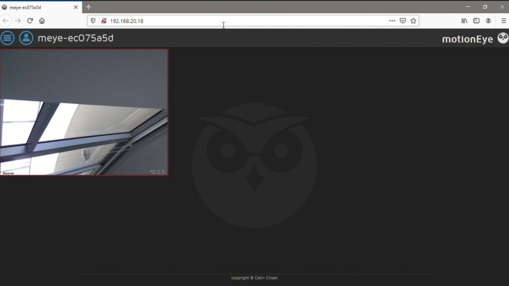
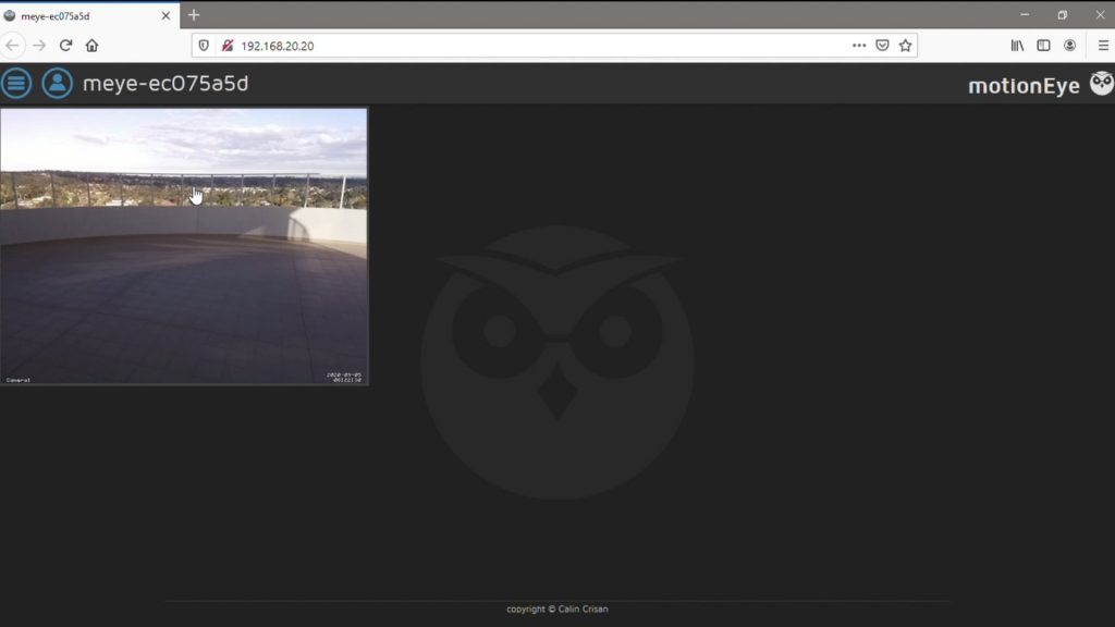
Once you’ve found the address, type it into your browser to access the Pi and it’s video feed.
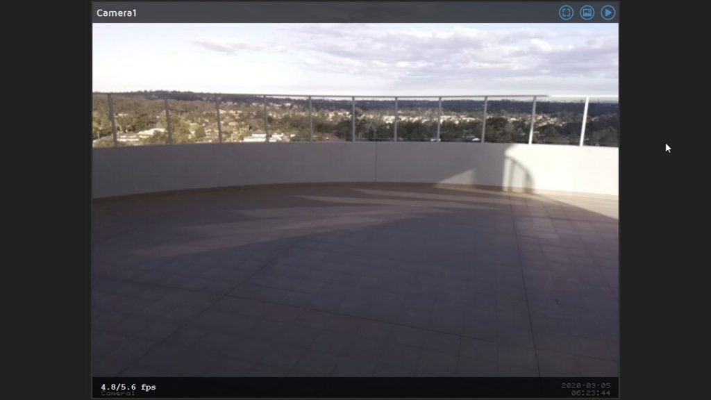
If everything is working correctly, the video feed from your camera should show up after a few seconds.
If you open up the settings menu, you can also shutdown or restart your Pi, which you’ll need to do if you’re going to be disconnecting it to install elsewhere. If you’re asked for login details, the default username is admin, with no password.
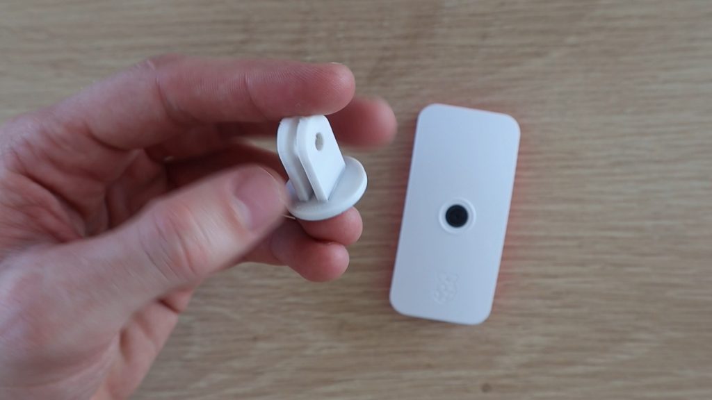
Mounting Your Camera
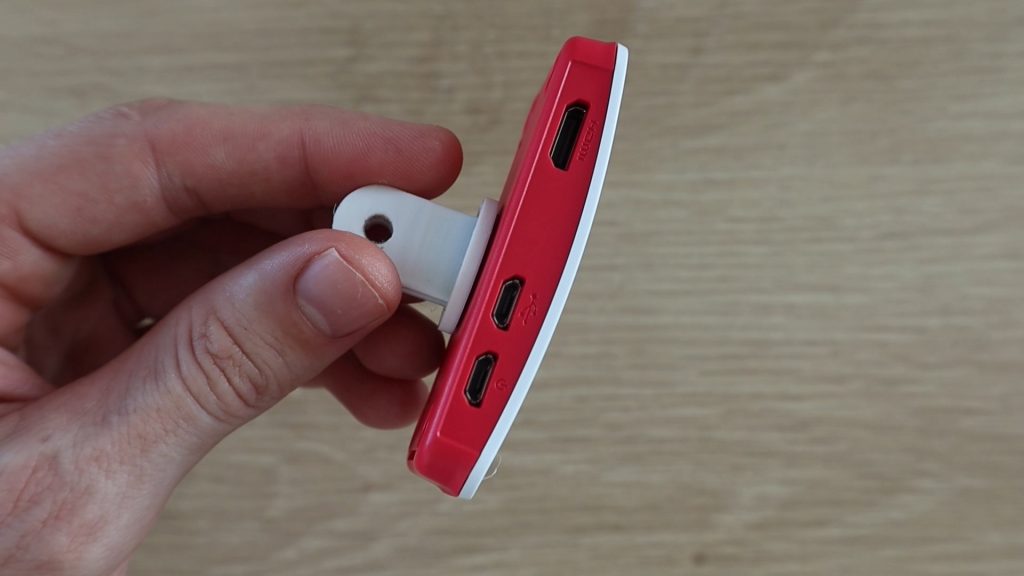
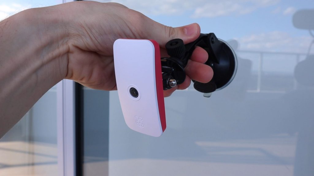
I 3D printed a small GoPro adaptor to stick onto the back of the Pi case so that it can be mounted onto any standard GoPro mounts.
I’m going to be using a suction cup mount to mount the Pi onto an outside window. It’s under cover, so it’s protected from direct sunlight and rain.
This mount also enables the camera to be positioned so that it’s pointing in the right direction.
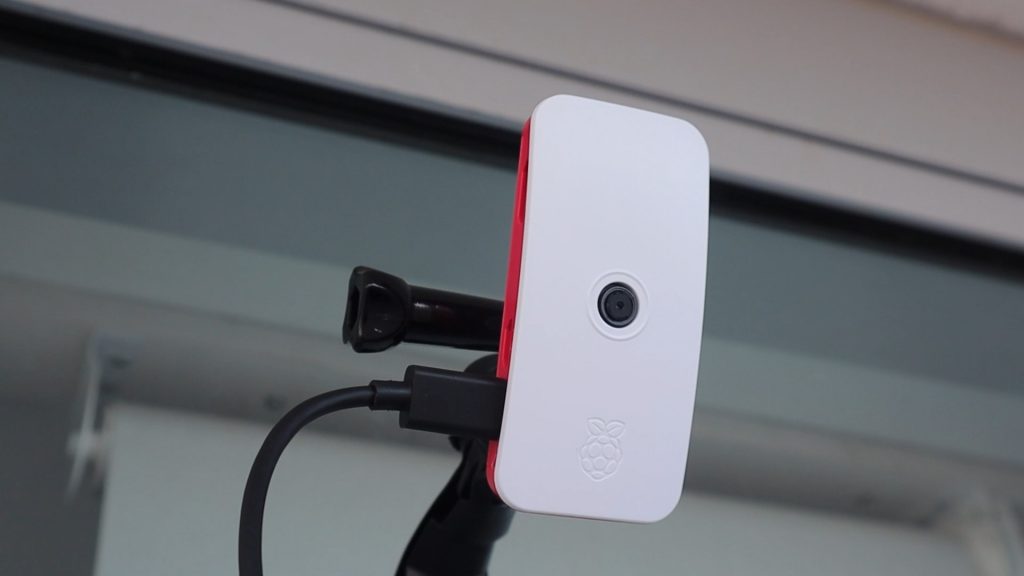
You’ll need to power it using a USB power supply. You can also use a power bank to temporarily power it for a mobile surveillance system.
Let’s have a look at the video feed outside.
You can also access the camera using your mobile phone or tablet by typing the same IP address into your device’s browser.
Configuring Port Forwarding To Access Your Camera Over The Internet
The last step is to configure port forwarding on your router, so that you can access the camera from the internet.
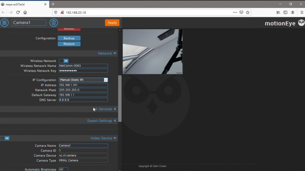
You’ll need to start by assigning a fixed IP address to your camera, so that it doesn’t change every time it re-connects to the network. This can be done in the MotionEyeOS settings menu. Set the IP configuration to manual and then change the IP address to the address you want to always assign to the camera. This should be out of the range that your router typically assigns addresses to otherwise you’ll land up with a conflict it that address has already been used.
For example, if your router typically assigns IP addresses in the 192.168.10.1 to 192.168.10.20 range then you should pick an address higher than 20, so something like 192.168.10.21 and onward for your cameras.
You might also need to change your Default Gateway to your Router’s address.
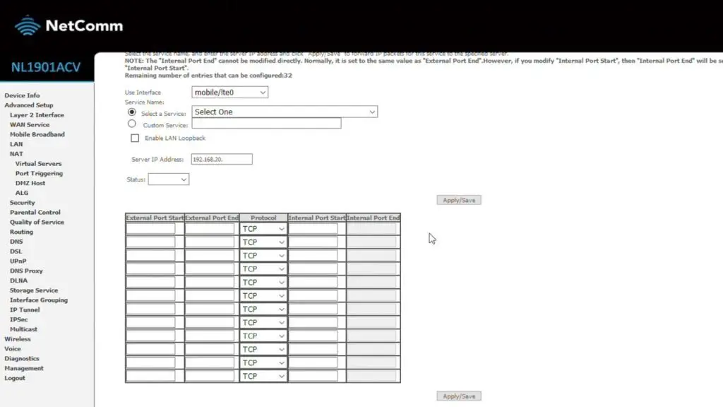
Next, you’ll need to set up port forwarding on your router. This is something I can’t really show you how to do because it’s very different for each router make and model. But you essentially need to login to your routers configuration page and then add a port forwarding instruction so that requests from outside your local network on a specific port are forwarded to a particular device, in this case, your Raspberry Pi camera.
Here’s the general idea of what you need to do:
You’ve got your Raspberry Pi’s local IP address (this is what you’ve been using to access the camera through your browser), you now need to know what port number it is communicating on. This is usually Port 80 by default. Since this is the default, it’s a good idea to change it to a port number that is unused by any other services as a security measure.
Next, you’ll need to find your router’s external IP address. This can be done by googling – “What’s My IP” from any device connected to the same internet-connected network.
This is the IP address you’ll need to type in over the internet in order to access your camera while you’re away from home. It is the IP address which your provider has assigned to your router. So this might change if you don’t have a fixed IP address arrangement with them.
Lastly, you need to choose an external port to forward. Again, you can choose any unused port. You’ll use the combination of your router’s IP address and this port number in your mobile device’s browser in order to access the camera.
Now that you have an external IP address and port as well as your internal IP address and port, you should have all of the information that you need to configure the port forwarding instruction on your router. This is the part that is very different for each router manufacturer and model, so you’ll need to figure out how to do this on your own router.
Essentially what you’re doing is telling the router that when an external request is sent to it on the particular port you’ve chosen, the router should forward the “web page” which is served to it when it calls the local IP address and port number so that you’re able to see it from outside the network.
Once this is done, you should be able to access your camera over the internet in the same way you could do it locally. If you’re still unsure how to do this, try searching for setting up Port Forwarding on your specific router make and model.
Let me know if you’ve built your own Raspberry Pi Zero WiFi Security Camera in the comments section. What are you using it for?
Last month, I built an Arduino based reaction timer game, which allows you to challenge your friends and family to see who has the fastest reaction time. We managed to get our times down to around 160 milliseconds and I’ve seen videos of people who can get down to 120 milliseconds, but now I want to know – How fast can an Arduino react to the same game?
Here’s a video of the test, have a look at it to see the Arduino react to the reaction timer’s LED, otherwise read on for the full write-up and details.
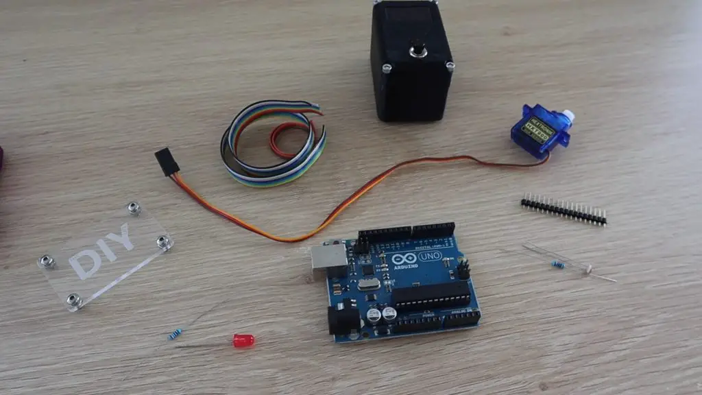
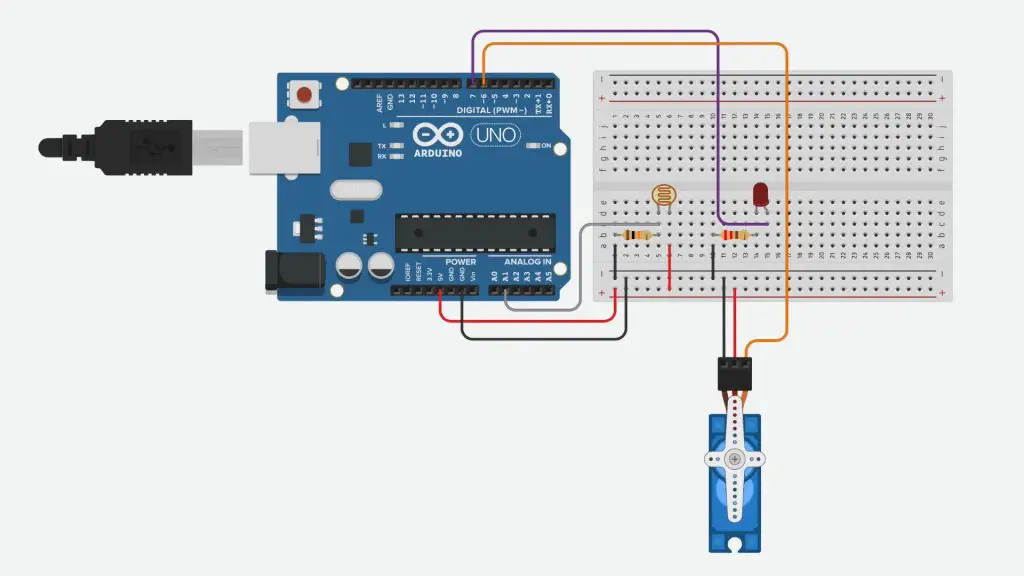
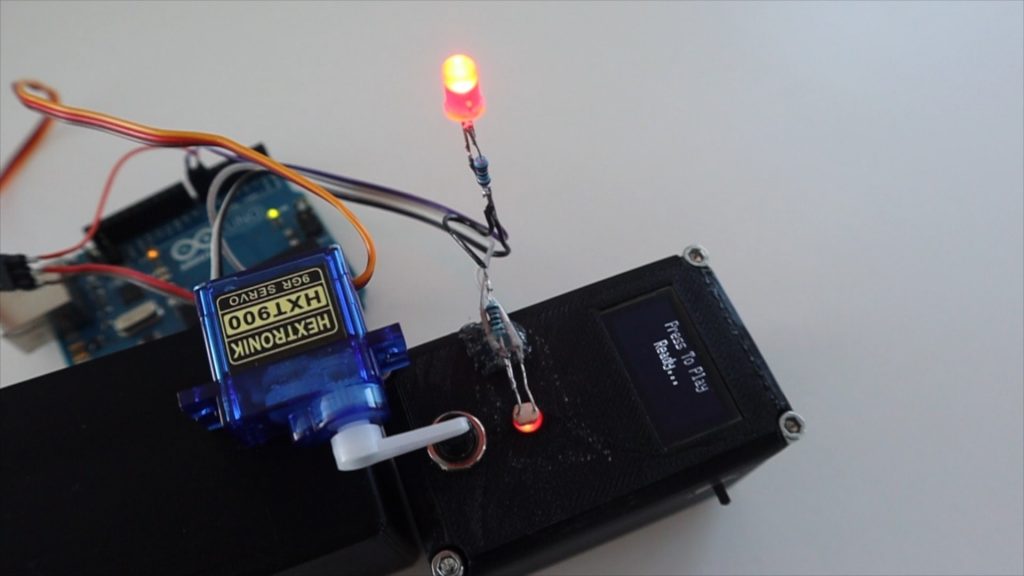
In order to test the Arduino’s reaction time, we’d need a sensor to detect the light coming from the LED on the game and then an actuator to push the button to stop the timer.
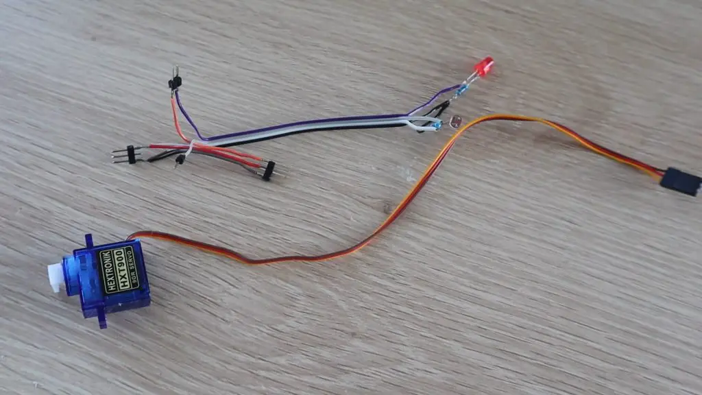
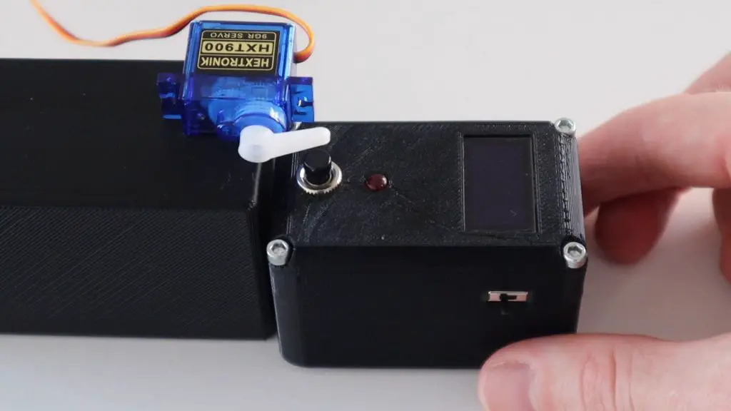
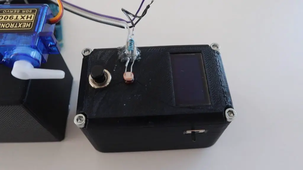
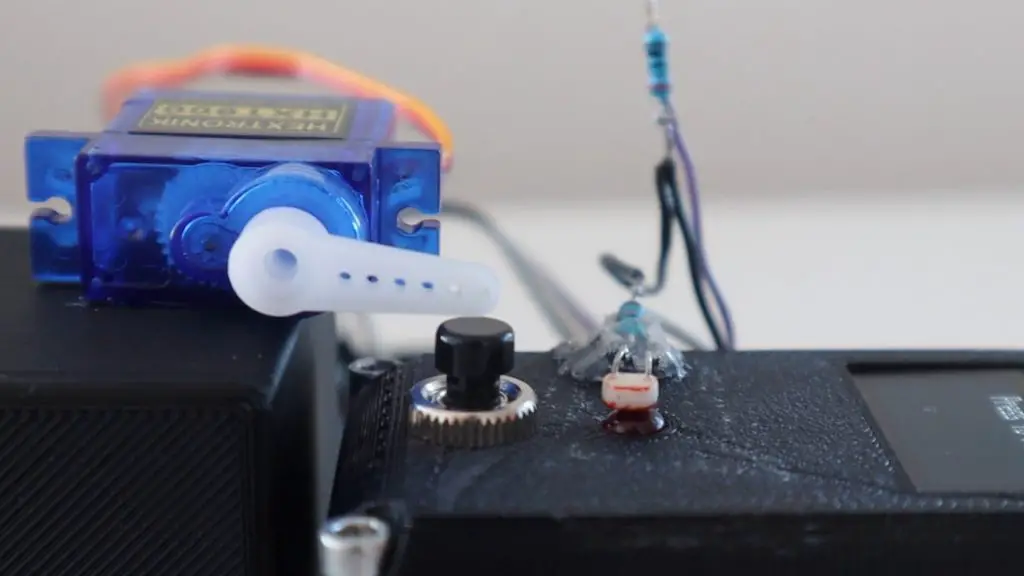
I built a simple setup with an LDR to detect the LED’s light and a micro-servo to push the button. I also included an LED so that we can see if there is any delay between the Arduino telling the servo to move and the servo actually pushing the button since there is a motor to spin up and a number of gears between the motor and the servo arm.
I soldered the components together using a few strips of ribbon cable and some header pins.
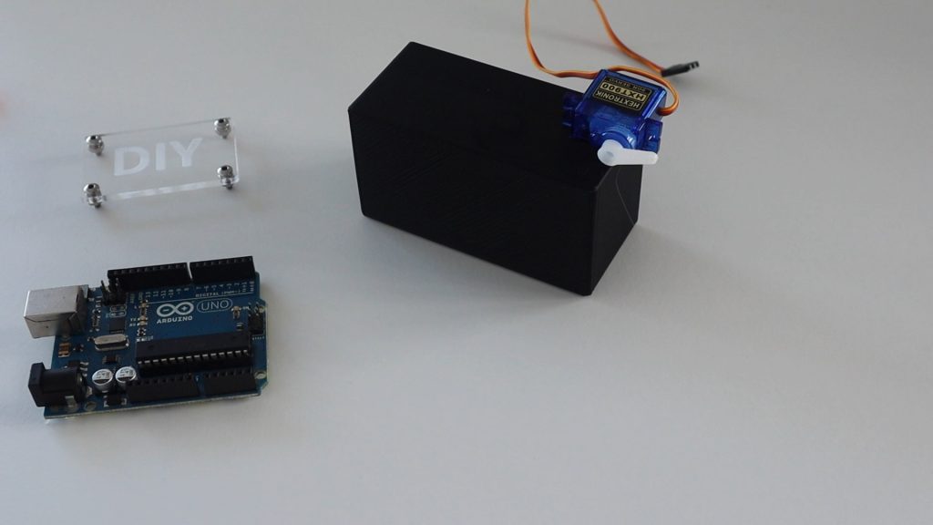
I then found a plastic base which was the right height to mount the servo on so that it could be positioned just above the button.
Next you’ll need to position the LDR as close to the LED as possible. I glued the resistor onto the side of the game using a glue gun and could then adjust the legs of the LDR to position it directly over the LED.
Now let’s have a look at the code.
//Michael Klements
//The DIY Life
//7 May 2020

#include <Servo.h>

Servo react;        //Create a servo object to control the reaction servo
int lightOn = 0;    //Variable to read in LDR value

void setup()
{
  //Serial.begin(9600);
  react.attach(6);    //Set the servo pin to pin 9
  pinMode(7, OUTPUT);   //Output pin for LED
  react.write(80);    //Set the servo to an initial position just above the button
}

void loop()
{
  lightOn = analogRead(A0);   //Read the output from the LDR
  //Serial.println(lightOn);
  if (lightOn > 800)
  {
    digitalWrite(7, HIGH);            //Light up the LED
    react.write(65);                  //Move the servo to push the reaction button
    delay(600);                       //Wait 400 milliseconds
    react.write(80);                  //Move the servo back to the initial position
    digitalWrite(7, LOW);             //Turn the LED off
  }
}
We start by including the servo library to control the servo.
We then create a servo object called react to control the servo and create a variable to store the value read from the LDR.
In the setup function we set the servo pin number, then set the LED pin as an output and set the servo position slightly above the reaction button.
In the loop function, we read in the LDR sensor level, then compare it to the light set point. If the measured level is greater than the set point, then we turn the LED on and then move the servo downwards to push the button. We then wait 400 milliseconds for the servo to move and then move the servo back up for the next push and turn the LED off again..
I’ve also included a serial monitor printout of the sensor value which is used initially to measure the game’s LED set point. You’ll need to run the game and see what value is measured by the sensor when the reaction timer’s LED is on and then update this value in the code accordingly. Once you’ve done this, then remove or comment out this code so that it is now slowing down the loop for the actual test. We’ll look at this in the next step.
Calibrating The Light Sensor
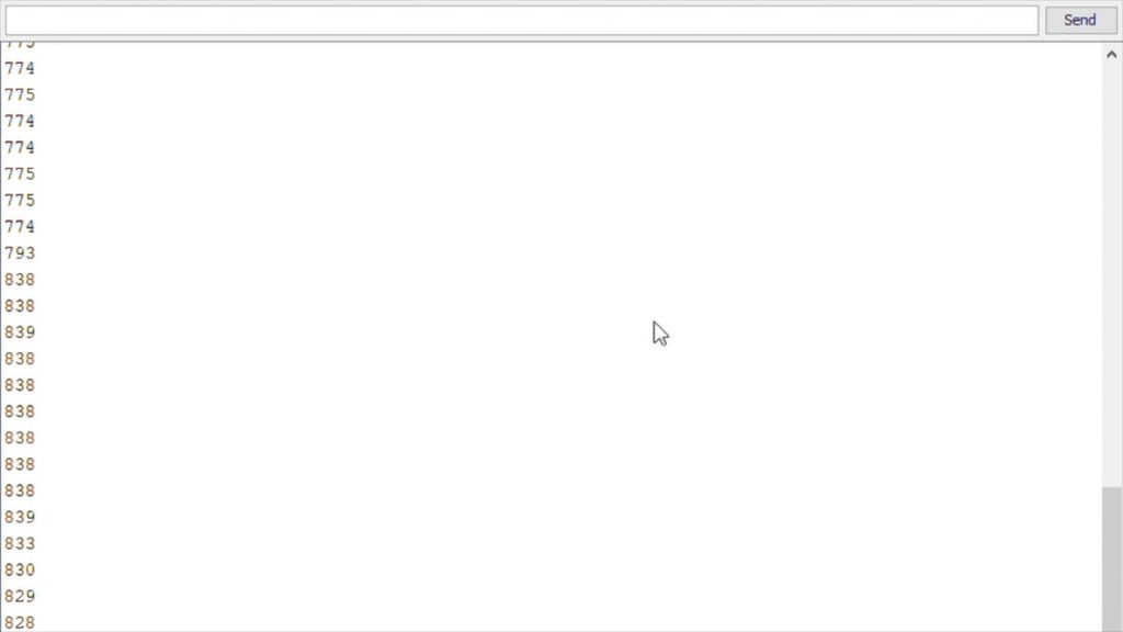
If we upload the code and then open the Serial Monitor, we get a stream of input values read from the sensor, detecting the ambient light. Now press the button on the reaction timer to start a game and look out for the change in values when the LED comes on.
You can see that we get a reading of around 775 when the LED is off and it goes up to around 830 when the LED is on.
We can now go change the setpoint value to a value just above the off value so that it triggers the servo movement as soon as the LDR starts to register the change in light. You want it to trigger as the LDR starts detecting the light change as the LDR will “slowly” ramp up to the maximum value over a couple of milliseconds.
Remember to comment out the Serial communication for the final version as you want the code to be as quick as possible.
Let’s upload the code and see how it quick it is.
Testing The Reaction Time Of The Arduino
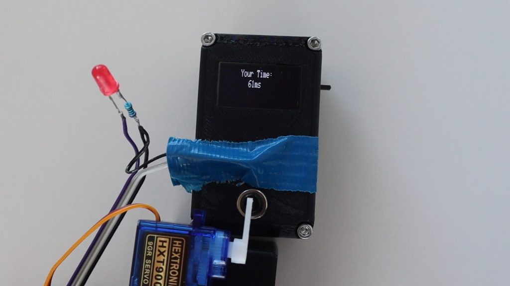
Press the button once to start the game and then quickly position it under the reaction servo.
For the first run, we get a reaction time of 54 milliseconds, which is pretty quick considering we have to wait for the servo to move to push the button as well.
I tested it a couple of times like this and consistently got around 50 to 60 millisecond reaction times.
Watching one in slow motion (included in the video at the beginning), you can see that the LED comes on really quickly after the reaction timer’s LED turns on, but there is a bit of a delay in getting the servo to move. By looking at the individual frames, I calculated that it takes around 8 milliseconds LED to come on after the reaction timer’s LED is turned on, the servo then takes around 50 milliseconds to press the button after this.
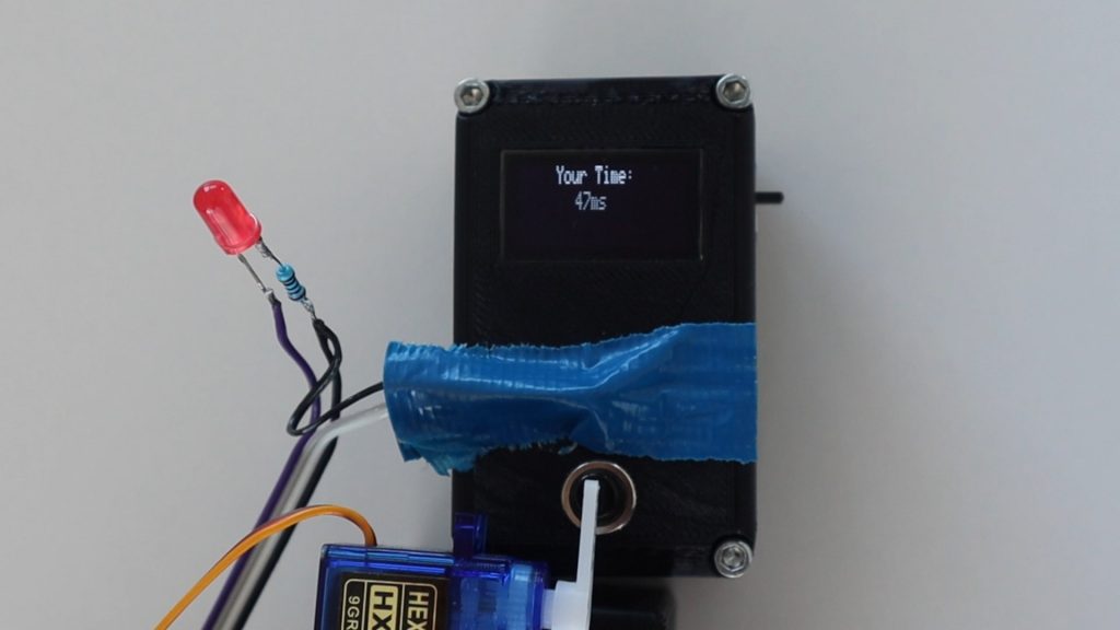
I then tried to see if making it darker around the LDR with some tape would result in a faster response time. It didn’t really make much of a difference, although there was a very slight improvement of around 1-3 milliseconds.
I also tried disabling the LED so that the Arduino just had to move the servo, this improved the reaction time by almost 10 milliseconds, so I got times around the mid-forties.
Conclusion
So from this test, we can see an Arduino react to an external light source in under 10 milliseconds, the servo movement takes up most of the reaction time from there. With the movement of a servo, the response time is just less than 50 milliseconds.
There are ways to further improve an Arduino’s response time by using Direct Port Manipulation, but this is probably not going to make a significant difference in this example, as the delays in the LED lighting up, the LDR responding to the light and the second LED lighting up is much more significant than the amount of time the Arduino takes to respond to the input.
Have you tried building any projects which required your Arduino to react quickly? What have you built? Let me know in the comments section below.
I recently looked at how much power some common Arduino boards consume and how long we’d be able to power them using one or two 18650 batteries. I found that I could power a 3.3V Arduino Pro Mini using a single 3.7V lithium-ion 18650 battery for 117 days in lower power mode. This got me thinking. What else could be done to make the Arduino Pro Mini even more power-efficient? How long could I get it to last? So I did some research and testing to find out.
For each test, I’ve included two battery capacities in my calculations, one for the 4200mAh claimed on the test batteries and one for the more commonly available 3500mAh batteries. I’ve then calculated the number of hours, days and years of run time for each modification and each battery. I’ve put these results into a table at the end.
Here’s the video of the modifications and the results, otherwise read on for the full write-up.
Testing The Standard Board With A Single 18650 Battery
Let’s start with the standard board with no power-saving or sleep mode active and no hardware modifications to use as a baseline.
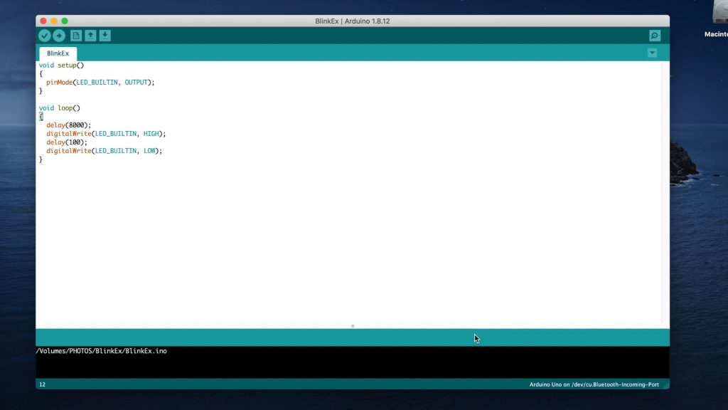
I loaded a basic sketch onto the Arduino which simply waits 8 seconds, then flashes the onboard LED for 100 milliseconds.
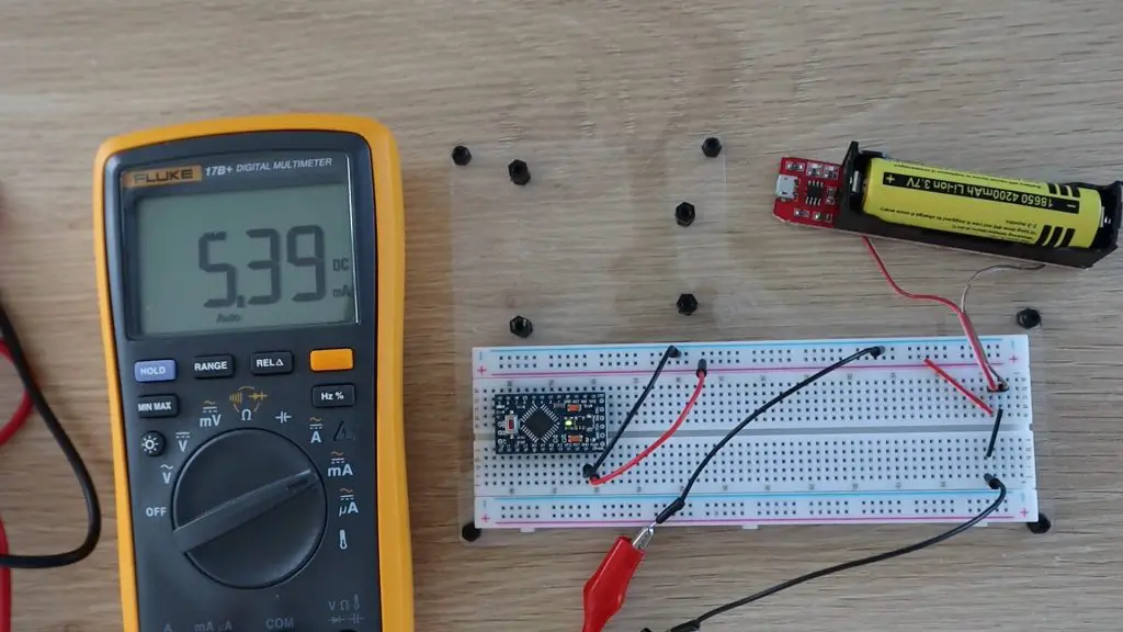
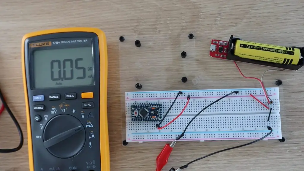
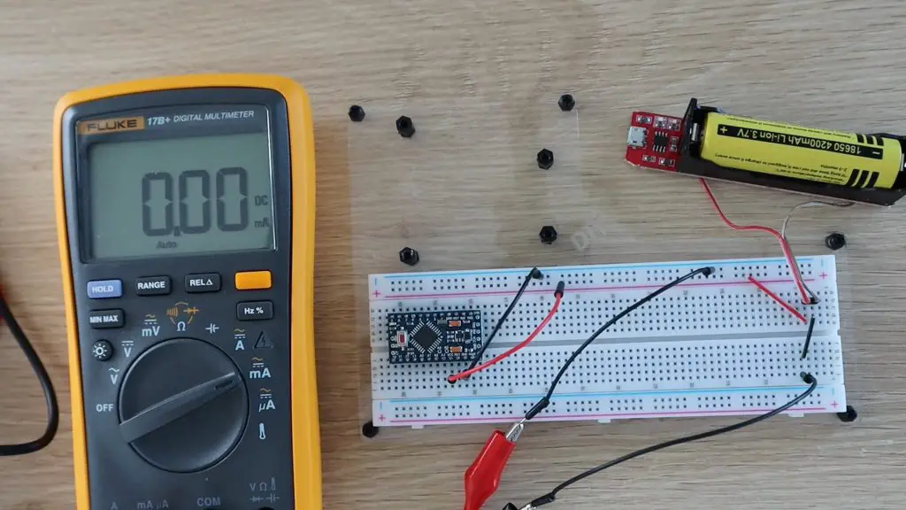
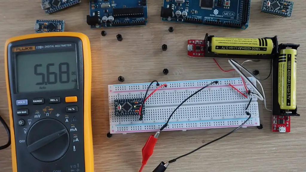
I then connected the single lithium-ion 18650 battery to the GND and RAW pins with the multimeter hooked up on the GND lead to measure the current being supplied to the Arduino.
So with no modifications, a 3.3V Arduino Pro Mini uses around 5.4 milliamps. Meaning that it could run for around a month on either the 4200mAh or the 3500mAh battery, the difference is only a couple of days.
Testing Low-Power Sleep Mode
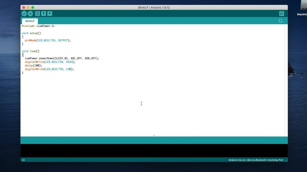
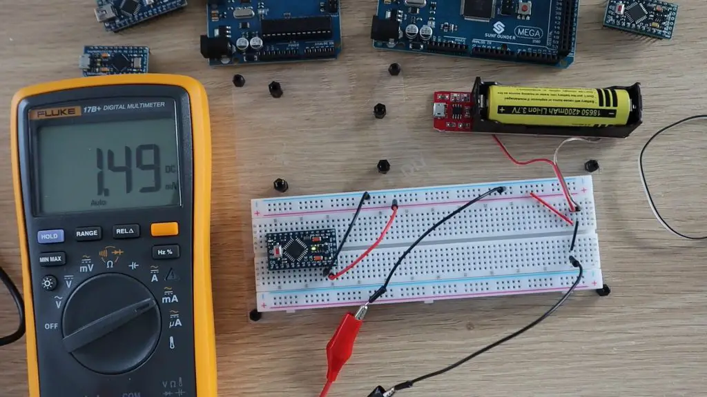
The Atmega chips on the Arduino Pro Mini supports a number of different sleep modes that turn off any unused peripherals in order to conserve power when the Arduino is running on batteries. So let’s try putting the Arduino into a low power sleep mode between flashing the LED, using the following sketch and the LowPower library.
We’ll keep all of the connections and hardware the same the same for this test.
So this mode has decreased the current draw to around 1.5 milliamps, which means that the Arduino will last almost 4 months on the 4200mAh battery and a little over 3 months on the 3500mAh battery.
Remove The Built-In Power LED
Now let’s try making some physical modifications to the board in order to conserve more power.
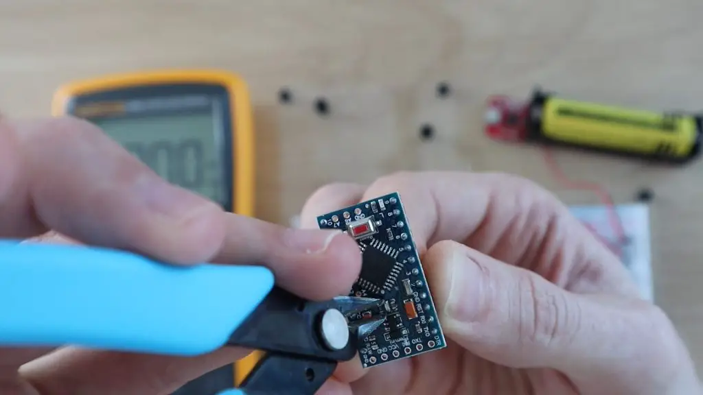
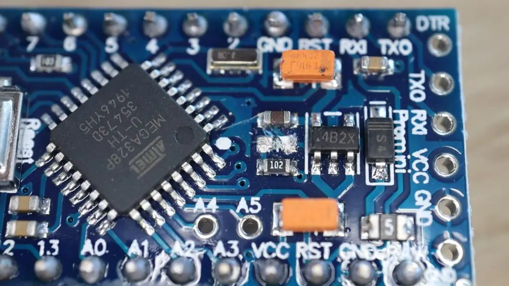
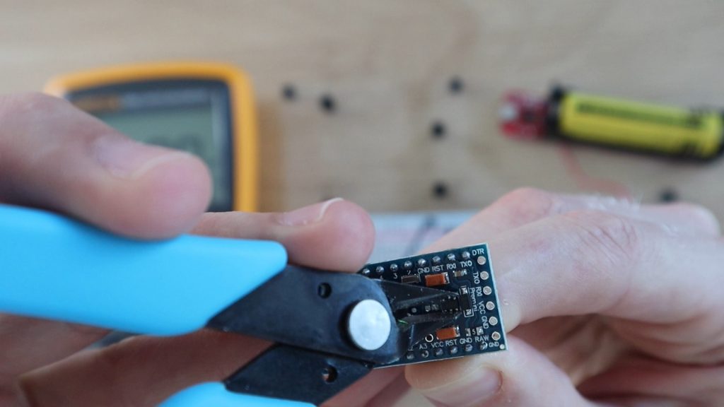
The first and probably most obvious thing to do is to get rid of the on-board power LED. These small LEDs don’t draw much power, but when we’re trying to power the board for over a month using a single battery then even small consumption items like these can become significant. It’s also not particularly useful to have an onboard power LED if the board is going to be in a housing or box.
Because its a surface-mounted component and there are components alongside it, the easiest way to disable it is to break it off of the board with pliers or some wire cutters. You could also cut through one of the supply traces on the PCB.
Now let’s see what improvement we’ve made.
Here’s the current draw shown in milliamps.
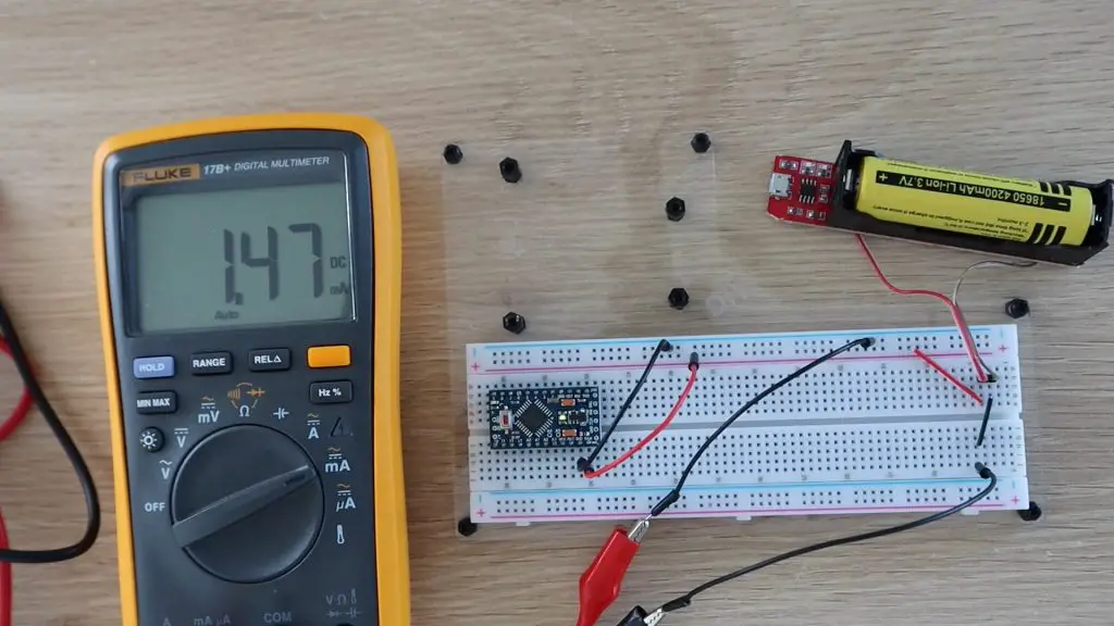
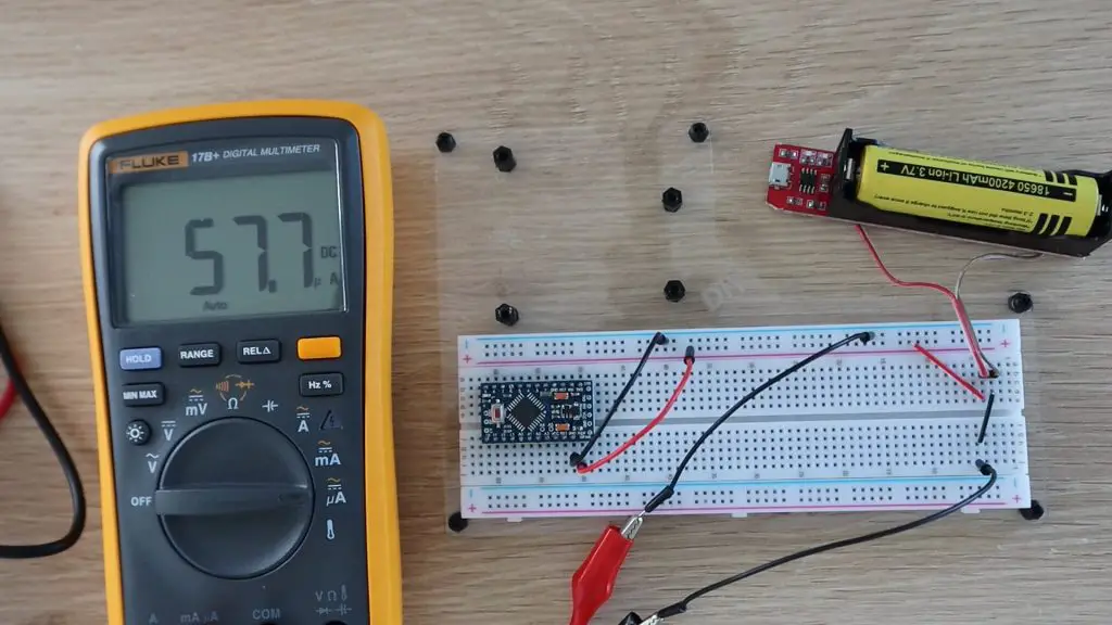
Let’s try switching the multimeter to microamps to get better resolution.
So the supply current has reduced from 1.5 milliamps to 0.058 milliamps or 58 microamps, which is a substantial saving. We’re now using 25 times less power than with just the power-saving mode activated, and all we’ve done is remove an LED which we probably wouldn’t have seen anyway.
So we’ve got an extra 2900 days of run-time by removing the LED. Your Arduino should now last for 8 years on a single charge on the 4200mAh battery and 7 years on the 3500mAh battery.
In practice, this will obviously be less, because your Arduino will also be doing some more complicated processing between sleep cycles, not just flashing an LED, but depending on how often and for how long it wakes up, this is what is possible.
You’ll also need to consider that an 18650 battery has a charge life of around 1 year, meaning that it slowly loses its charge over about a year to a year and a half. So your battery is actually losing its charge faster than the Arduino is using the power. If you’re going to be building really long term projects then you’ll probably want to use non-rechargeable batteries as these typically have a longer shelf life. Non-rechargeable lithium batteries generally have a shelf life of around 10-12 years.
For most projects, 8 years is more than enough and your components will likely pack up before the battery is empty. But why stop there? Let’s see if there is any other way we can further improve battery life.
Remove The Onboard Voltage Regulator
The next thing I’m going to try is to remove the voltage regulator. The 3.3V regulators which are typically used on these boards are not very efficient at very low currents, you usually only get around 10-20% efficiency on the low end of thecurve. Replacing the regulator with a linear regulator, such as an MCP1700 will dramatically improve the battery life of your Arduino as well. This is a bit more complicated to do, you’ll need a steady hand and some patience to remove the surface mount voltage regulator from the board and replace it with a new one.
The other option is to remove the voltage regulator altogether. The ATmega328P chip can actually support input voltage levels between 2.7V and 5.5V, however the voltage on the IO pins will vary with the input voltage as well. This may not be a problem if your IO devices can handle the fluctuating voltages, as is often the case with LEDs, pushbuttons and relatively simple OLED displays. We’re going to try this method and see if the Arduino will still run and flash the onboard LED while using less power during sleep.
In order to remove the voltage regulator, I also just used some wire cutters and pulled the regulator off of the PCB.
You’ll also need to make a slight modification on your breadboard. With the voltage regulator removed, you’ll now need to power your board by connecting the 18650 battery to the GND and VCC pins. Connecting the battery to the GND and RAW pins will do nothing.
With the multimeter in milliamps, it doesn’t even register the current draw, but the LED is flashing, so the Arduino is still working.
Let’s try switch it to microamps.
With the voltage regulator removed, our board is now drawing 5 microamps in sleep mode.
At 5 microamps we’re now up to 35,000 days on a single 4200mAh 18650 battery. This is also now pretty close to what the ATmega datasheet claims for power down sleep mode, so it’s unlikely that we’ll be able to reduce this much further.
You’ll notice a brief spike in the current reading when the LED flashes as the Arduino wakes up and supplies power to the LED.
So we now have an Arduino which will theoretically run for 96 years on a single 18650 battery. That’s way better than I thought we’d be able to do!
Let me know in the comments section what low power projects you’ve built using an Arduino and how long your batteries typically last.
With environmental consciousness rising globally, many homeowners are starting to recognize the importance of building a sustainable home. Even the Hollywood stars are seeing the impact of their lavish lifestyles and realizing how they can sometimes be unsustainable. While some are putting effort into creating energy-neutral homes, others are becoming green activists. While us, regular folks, may not change the homes we live in entirely, we may improve our ecological footprint by borrowing some ideas from sustainable homes. And the best part – most of these ideas involve DIY in one way or another.
Food
The first thing that comes to mind is food. Organic, locally grown food is your aim. Every patch of land around your home can be used to grow your own food. Even the inside of your home can serve this purpose. While you may not be able to make this the only source of your food, you can reduce your costs a lot. Investing in a greenhouse will provide you with vegetables throughout the year. More ambitious people can consider building a DIY fishpond or even growing a couple of chickens. It doesn’t take that much work. Of course, these are the options for those that have the space for this.
Energy
First, keep the energy and heat lost that you already spend to the lowest. This is achieved by insulation, responsible consumption and eco-friendly appliances. These are the things that every sustainable household has. The next steps are the solar panels and wind turbines. Needless to say, investing in these energy sources pays off in many ways. A lot of people choose to install these systems themselves, especially when it comes to home insulation. Making and installing your own home insulation can save you a lot of money, and the best part is that it can be done in an eco-friendly way by using cellulose fiber.
Solar power
One of the cleanest, greenest, and most sustainable ways to power your home is by relying on solar energy. The best place to start would be to learn more about your home’s energy efficiency. Next, you want to assess your home’s solar potential and estimate how much solar electricity your home will need. After that, you can proceed to obtain bids from solar installers. In order for your home solar power system to perform at an optimal level, you’ll also need to invest in high-quality components such as a high-powered solar inverter while keeping in mind the size, capacity, input voltage, and the type of inverter. Installing a home solar power system can also earn you rebates and tax credits, not to mention the giant favor you’ll be doing to Mother Nature by switching to renewable energy sources.
Water
Water is recycled and harvested from the rain. The water that you use for showering and washing your clothes and dishes is cleared and used to water the plants in your greenhouse. A rainwater harvesting system can provide you with the majority of the water you need. This will cut down the yearly bills for water significantly. For this system to work, you need to make sure you have all the filters needed to avoid polluting the greenhouse with cleaning products you use. Perhaps you don’t have a garden to water or but you can build the system that will reuse that water for flushing. You can even build it yourself.
Comfort
Some people have prejudice when it comes to sustainable living. Regardless of their thinking, it doesn’t have to be basic and cave-like. All the perks of modern life are still there for you to use. You use energy and water in a smart way and get hold of it in a way that doesn’t involve paying for it. This is true for fully sustainable households. Yours doesn’t have to be that way, but it will definitely benefit from some of these things.
Living free from bills, costs and credit rates in your own solar home is a dream come true for many people. Some of them even managed to pull this off and now they live fully sustainable lives. However, this kind of life means changing all your habits entirely. For the time being, using the experience of sustainable living to save some money and improve your home will be enough.
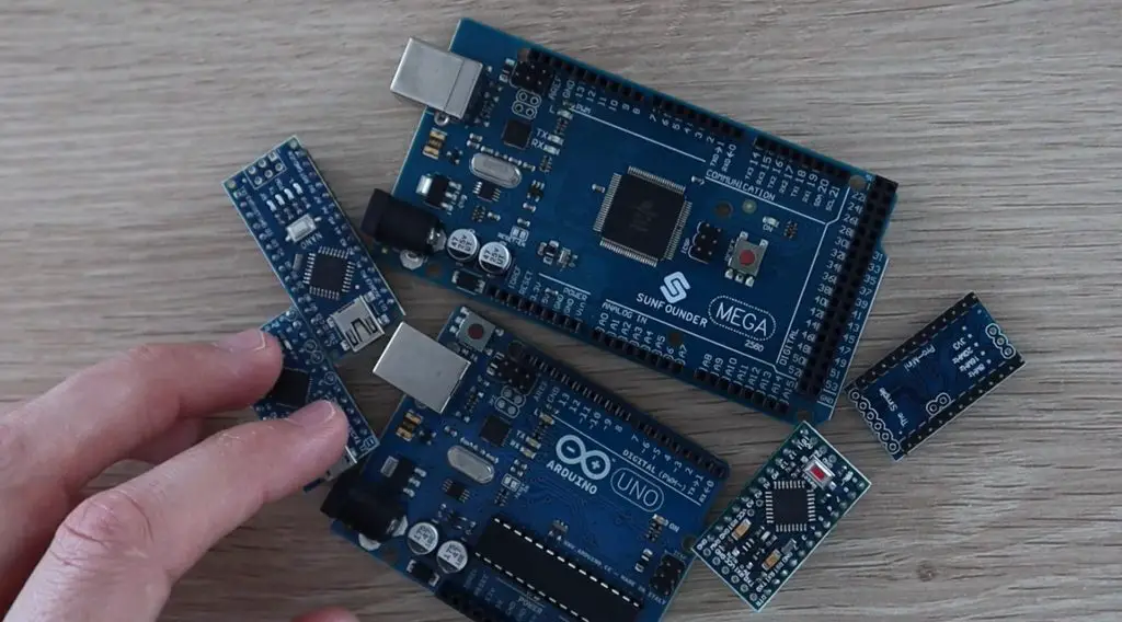
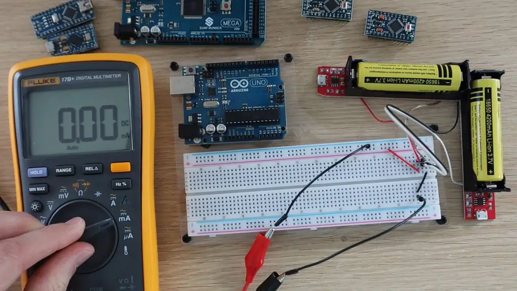
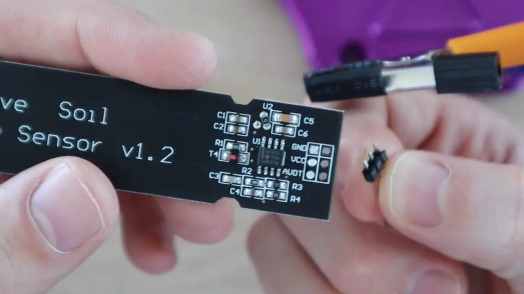
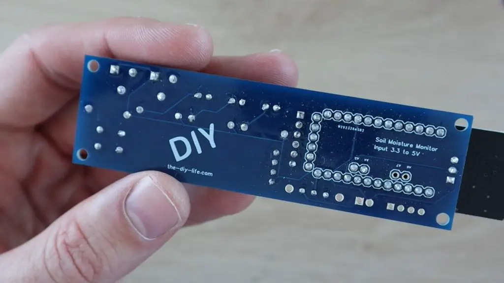
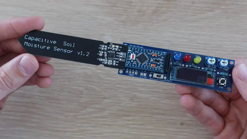
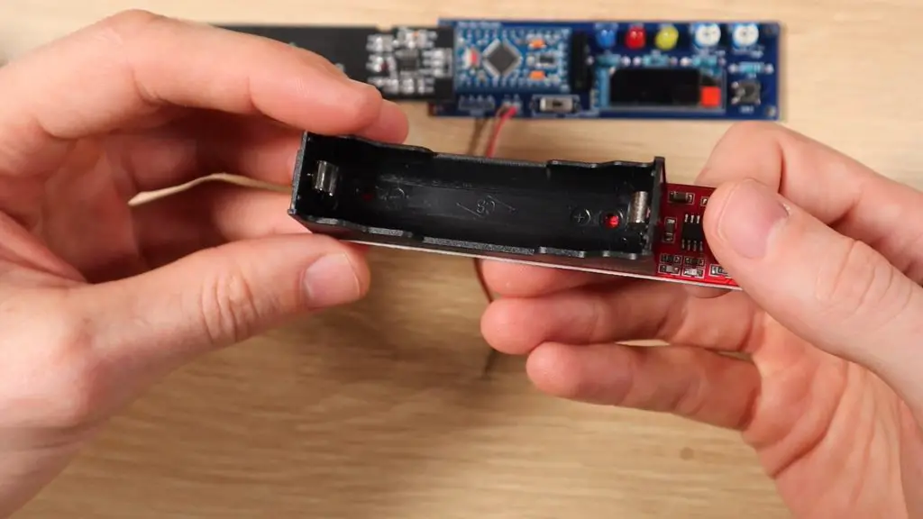
I recently built a soil moisture monitor, which relies on a 18650 lithium-ion battery to power it. This got me wondering which Arduino would be best to use for a battery-based project and what can be done to improve the battery life. So, in this test, we’re going to be looking at the power consumption of a number of different Arduino boards with the aim being to try and power them for as long as possible using two 18650 lithium-ion batteries.
Here’s a video of the test, read on for the test write-up:
Setting Up The Test Rig
Let’s get started by showing you what I’m going to be using for the test and how I’m going to be testing each Arduino using the batteries.
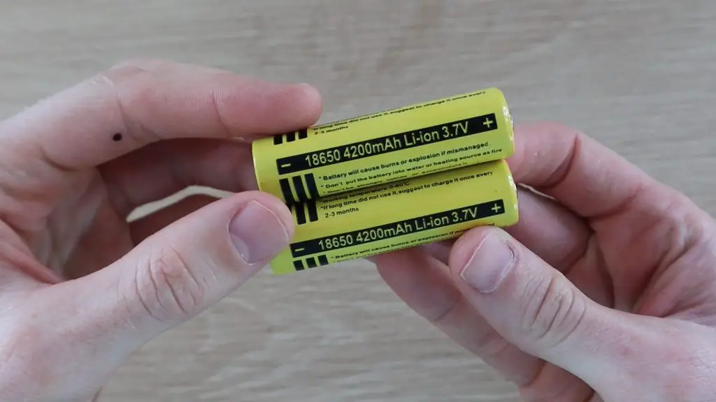
These 18650 batteries are 3.7 voltage each and come in a range of capacities from around 1800 to 4500mAh. The ones used for this test are on the higher end, at 4200mAh, meaning that they can supply 4.2mA for 1000 hours or 420mA for ten hours or any combination of current and time for which the product is 4200.
Most Arduino boards require a minimum input voltage of around 6V, so we’ll be powering each Arduino using two batteries connected in series, with an input voltage of 7.4V to power these boards. I’ve also included a 3.3V Pro Mini, which is able to run on a single battery as a comparison.
I’m going to be loading a basic sketch onto each Arduino which has has an 8 second delay and then flashes the onboard LED for 100milliseconds just to tell us that the sketch running and this will just loop repeatedly.
The Atmega chips on these boards support a number of different sleep modes that turn off any unused peripherals in order to conserve power when the Arduino is running on batteries.
I’m not going to go into too much detail on how this works, but we’ll be using a low power library that enables you to put the Arduino to sleep for a certain amount of time or until an interrupt is triggered.
So, I’ll include two tests for each board, one without sleep mode and one in which the Arduino is put to sleep for the 8 seconds between flashes instead of running a delay. I’ll discuss this option a bit later when we look at the difference in power consumption.
I’ve connected the two batteries in series and then connected them to my multimeter to measure the current draw. The multimeter is going to be showing the current drawn in milliamps.
Now that the test rig and sketches are ready, let’s start testing the Arduinos.
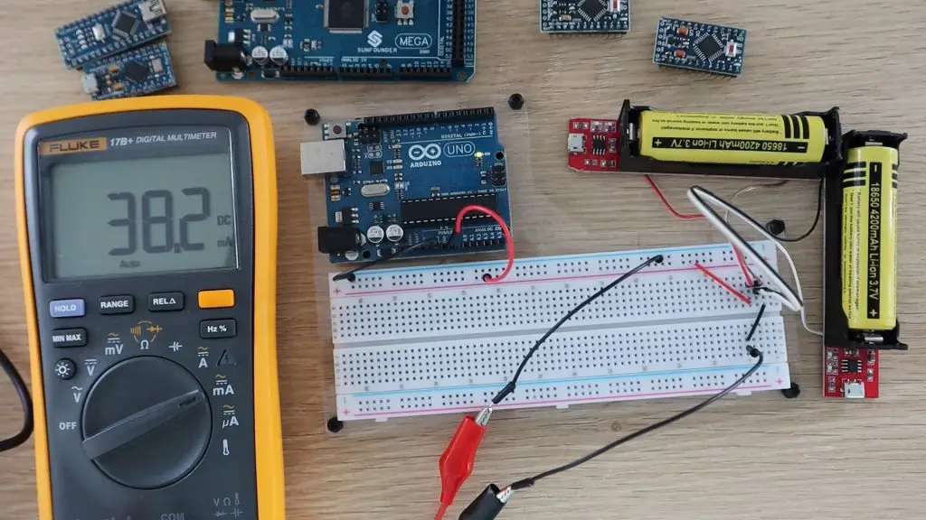
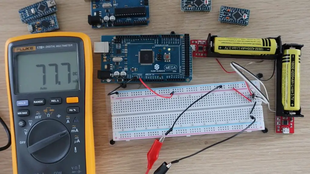
We’ll start off with the Arduino Uno, since it’s one of the most common boards available. This board is designed to be robust and easy to use rather than power efficient or compact, so I doubt it’s going to do very well in the power test, but let’s try it out as a starting point.
In each test, I’ll allow the current to stabilise for a bit and then record the average current drawn during the delay time. We’ll ignore the peak current drawn while the led flashes as this only happens for 100 milliseconds every 8 seconds, which is only around 1% of the time.
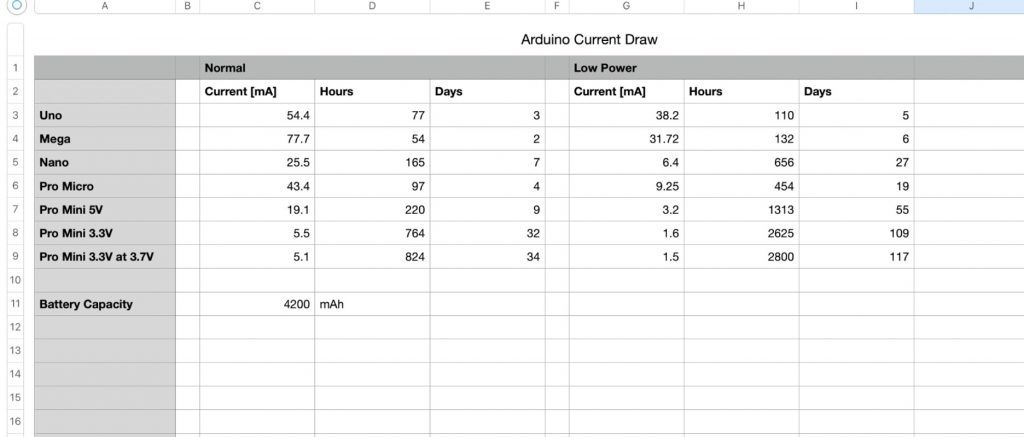
On the Uno in normal mode, we get a current draw of 54.4mA, which means it would run for about 77 hours or three days on the two 18650 batteries.
Now let’s load the sleep sketch and see if there is any difference.
If you watch the video, you’ll notice the current spike briefly when the LED flashes and then return to the low power mode current draw.
So if we use the sleep mode between flashes, the current consumption goes down to 38.2mA. So we expect it to be able to run for around 110 hours or 5 days.
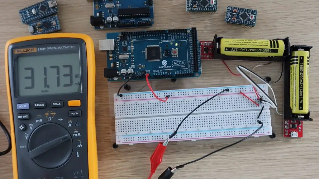
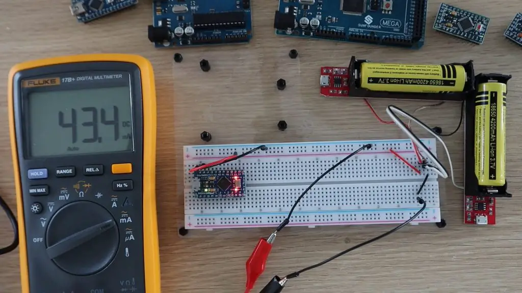
Now let’s try an Arduino Mega. We’d expect the Mega to be the worst performer as it’s the largest board, has the most IO and the most complex chip on it.
As expected, this board draws a bit more power than the Uno, it draws around 77.7mA, so it would only last for 54 hours or 2 days.
Now let’s look at the Mega in low power mode.
So in low power mode, an Arduino Mega draws around 31.7mA and would run for about 132 hours or 6 days.
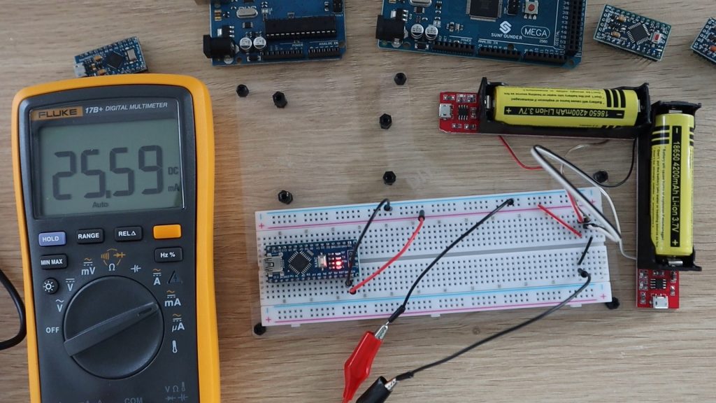
Next we have a Nano. I’d expect the Nano to be the most efficient board so far as it’s designed for smaller, more portable projects and is a lot more compact than the Uno or Mega.
The Nano seems to be a lot more efficient than the Uno or the Mega. The Nano draws 25.5 milliamps, so we’d expect it to run for 165 hours or 7 days.
Now let’s try the Nano in low power mode.
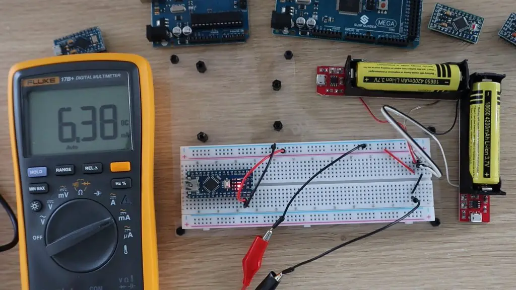
Using the sleep mode sketch, the Nano draws only 6.4 milliamps, so it would run for around 656 hours or 27 days. So we’re almost at a month. Let’s see if the Pro Micro can get to a month.
Next let’s try a Pro Micro in normal mode.
The Pro Micro actually did a lot worse than the Nano, which I didn’t expect. I thought that it would be similar, if not better, than the Nano. It drew around 43.4mA, so it would last for only 97 hours or 4 days.
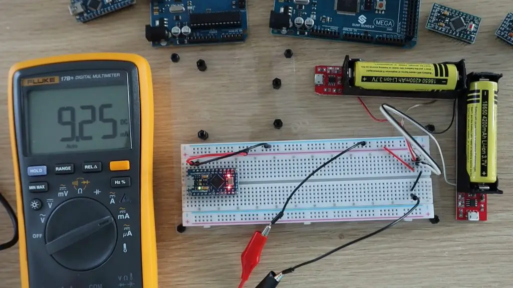
Now let’s try low power mode.
In low power mode, the Pro Micro drew 9.25mA, so it’s much better than the Mega and Uno but the Nano is still the most efficient.
Next, we’re going to try powering a Pro Mini. This is a very similar form factor to the Pro Micro but it has a different chip and the onboard USB host has been removed, so you need an external programmer to connect it to your computer.
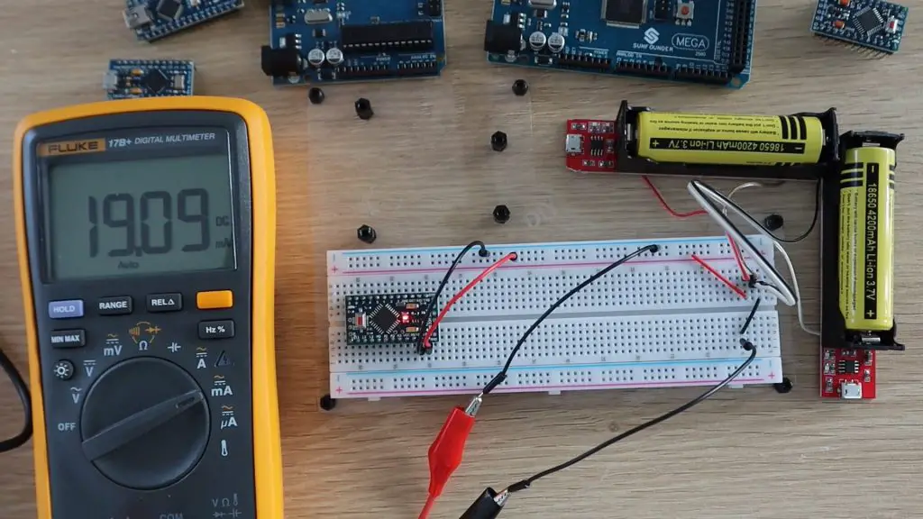
First we’ll try the 5V Pro Mini in normal mode.
The Pro Mini uses just 19.1mA, which is a little less than the Nano, and means that it will last around 220 hours or 9 days.
Now let’s try the 5V Pro Mini in low power mode.
If we put the Pro Mini to sleep between flashes, it uses just 3.2mA, which means that it will run for 1313 hours or 55 days, we’re now getting closer to 2 months.
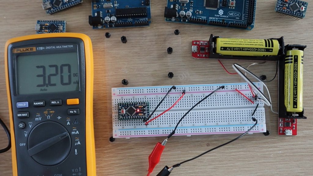
Lastly, let’s try the 3.3V Arduino Pro Mini and see if it does better than the 5V version. We’ll still be powering the 3.3V Pro Mini using the two 18650 batteries for this first test.
The 3.3V Pro Mini draws substantially less current than the 5V version, just 5.5mA, which is even better than the Nano in low power mode. So it will run for a month in normal mode, let’s see how long it will run in low power mode.
The 3.3V Pro Mini uses just 1.6mA in low power mode, so it will run for around 109 days, which is a bit over 3 months.
Let’s see if that changes if we power it with just one battery. Remember that if we’re halving the input voltage, we’d expect the current to increase to supply the same amount of power to the Arduino.
Strangely, there was actually a slight decrease in input current. This is probably due to the onboard voltage regulator being more efficient at voltages closer to the operating voltage. So you’ll actually get better battery life by powering a 3.3V pro mini with a single 18650 battery. You’ll get almost 4 months.
The Results, How Long Can Each Arduino Run On Batteries?
Now that we’ve completed the test for each board, lets look at how long each Arduino can run on batteries.
The most power-efficient board in both modes is the 3.3V Pro Mini, lasting almost 4 months on a single 18650 battery.
There’s also a significant decrease in power consumption when using sleep mode, so you should definitely consider using it if you’re designing battery-based projects.
Now you obviously can’t have the Arduino sleeping the whole time, it’s actually expected to do something if it’s connected up to a project. But, on most projects where you’d be looking to power the Arduino using batteries, you’re only using the Arduino for a fraction of the time that the system is powered up.
For example, if we look at a soil moisture monitor, the soil doesn’t suddenly dry up in a couple of milliseconds, and even watering the plant takes a minute or two for the water to be evenly soaked up into all of the soil. Also, your plant isn’t going to die if its roots are dry for 2 seconds. So, you really only need to take soil moisture readings in minute intervals rather than every couple of hundred milliseconds. You could, therefore, have your Arudino sleep for a minute, then take the measurements over a few hundred milliseconds and then sleep again, so your Arduino would be sleeping for most of it’s “on” time.
Similarly, for weather stations, even rapid outdoor temperature changes only change over a number of minutes. So, you can set your Arduino to wake up every 5 minutes and take a new temperature and humidity measurements, rather than take measurements on every loop cycle.
It’s also important to note that there’s a difference between putting the Arduino to sleep and simply putting delays into your code. Delays don’t stop the Arduino from processing operations, they just tell the Arduino not to proceed until an amount of time has passed.
You can think of the two like this; putting a delay into your code is like having a child asking “are we there yet”, “are we there yet”, “are we there yet” over and over until the answer is yes and it’s able to proceed. Putting the Arduino to sleep is like setting an alarm and allowing the Arduino to do nothing until the alarm rings and wakes it up again. You’ll get much longer battery life by allowing your Arduino to do nothing between readings rather than constantly checking if the amount of time has elapsed.
Look out for the next test, in which I’m going to try and further reduce the power consumption of a 3.3V Arduino Pro Mini and see if we can get it to run for over a year on a single 18650 battery.
Let me know in the comments section what battery based Arduino projects you’ve built.
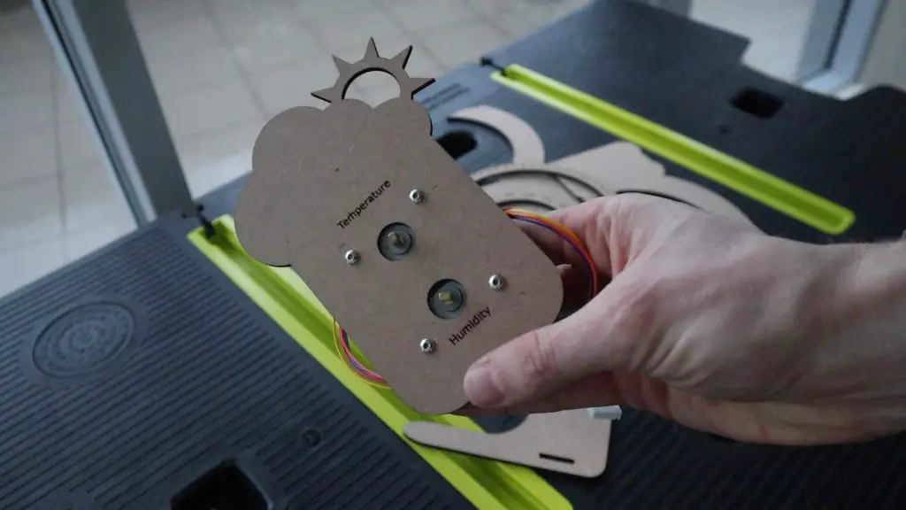
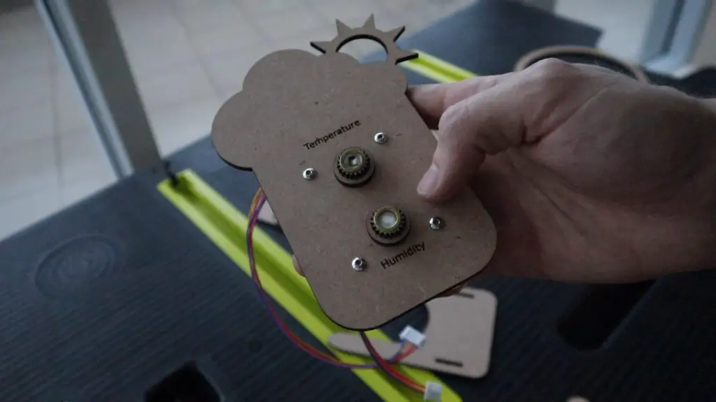
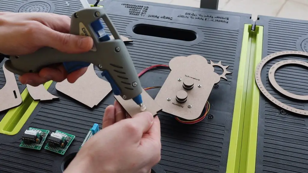
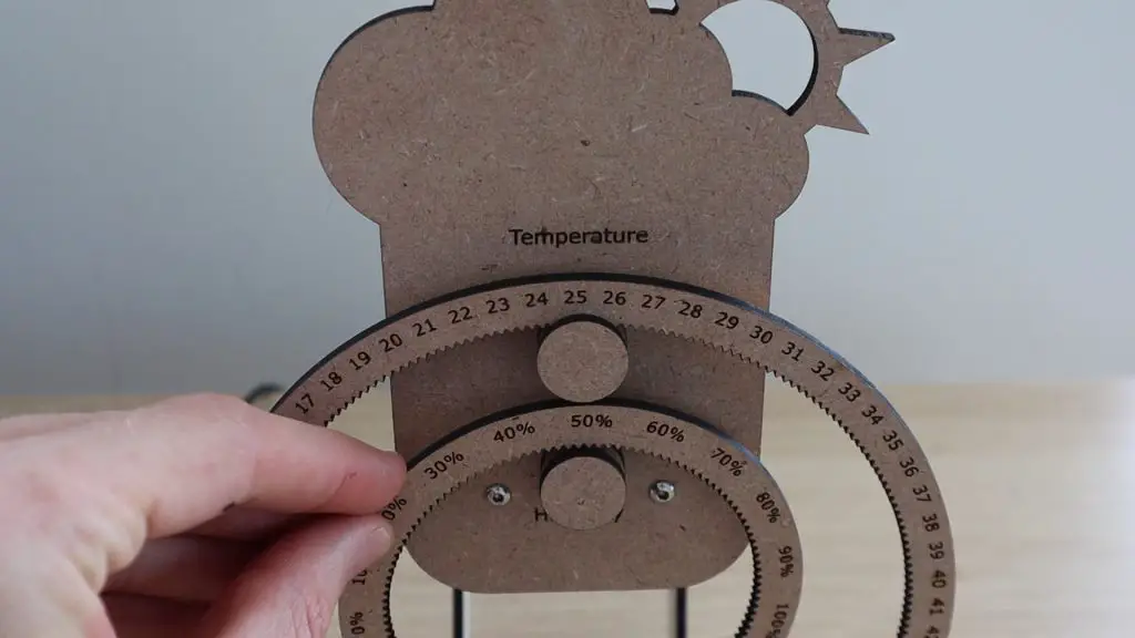
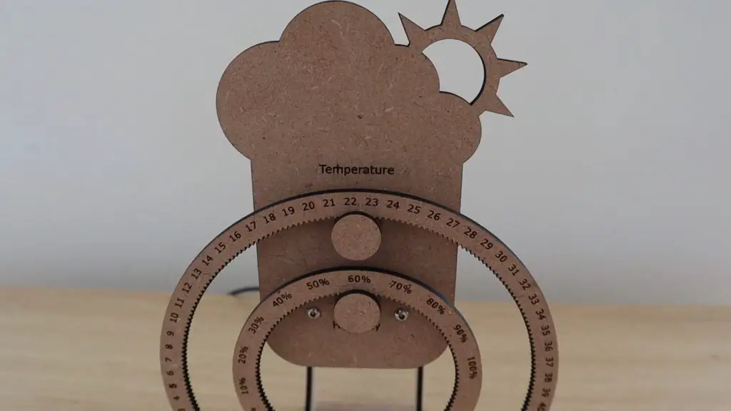
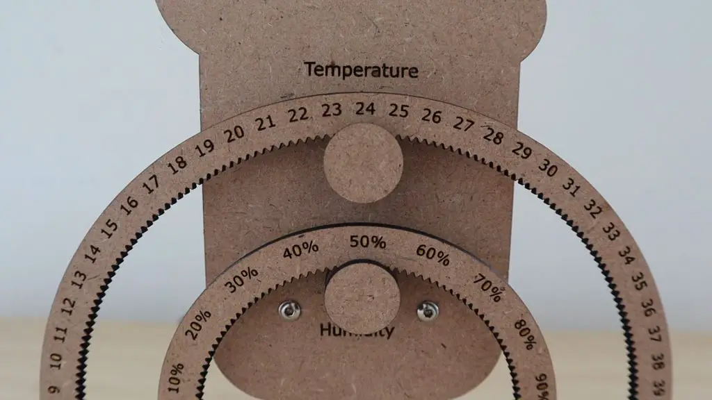
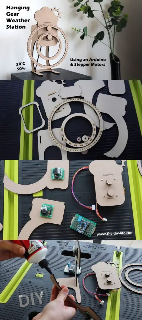
In this project, I’ll be showing you how to build your own hanging gear weather station, which is made from laser-cut MDF components. An Arduino Pro Micro uses a DHT11 sensor to take temperature and humidity measurements and then drives two stepper motors to turn the hanging gears to indicate the measured values.
The weather station is supported by two legs on a flat base, making it perfect to stand on your desk, or on a shelf or side table.
The DHT sensor has a range of 20-95% relative humidity and can measure temperatures between 0-50°C. I’ve designed the gears for the full humidity range and with a negative temperature range so that you can easily use a different sensor if you’d like to place the sensor outside to measure the outdoor conditions.
The stepper motors are almost silent and their noise level can be adjusted by slowing down their movement, so you won’t be bugged by them if you use the weather station on your desk.
Here’s a video of the build and weather station in operation:
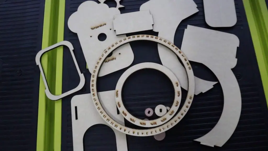
We’ll start off by laser cutting the MDF components, then assemble the electronics and install these onto the MDF components, then finish the assembly of the weather station and then finally program and set up the Arduino.
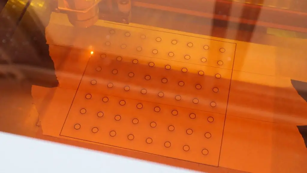
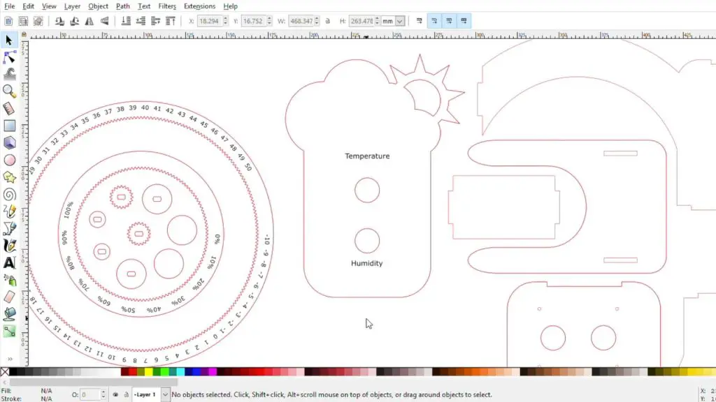
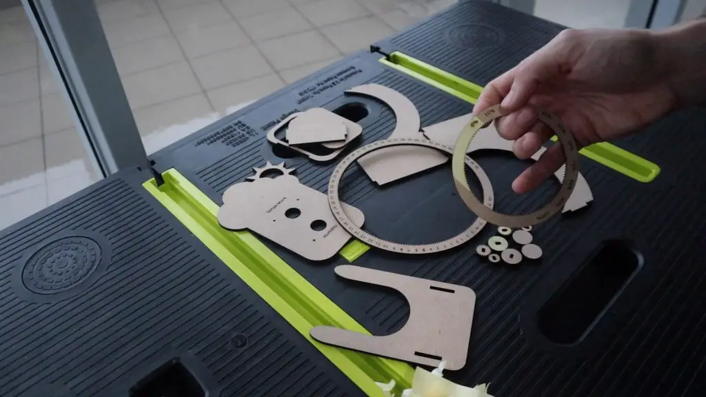
Laser Cut The MDF Components
I designed the laser cut components in Inkscape. The components are all on a single sheet in the download, so you’ll need to split them up to suit the bed size of your laser cutter.
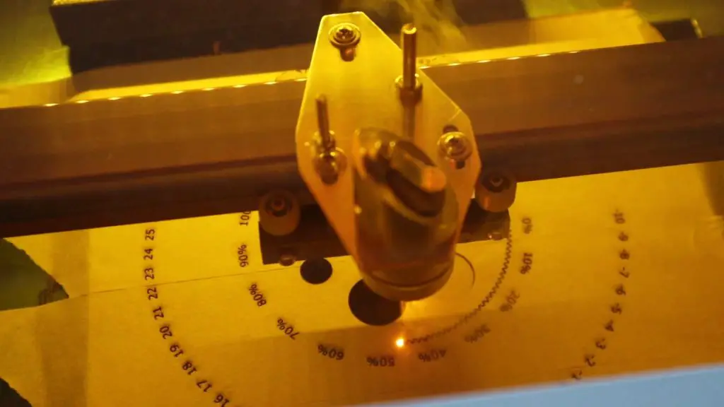
I used a cheap K40 laser cutter to cut and engrave these components. If you don’t have access to a laser cutter, consider using an online laser cutting service. There are a number of services available online and most will even deliver the components to you once they’re cut.
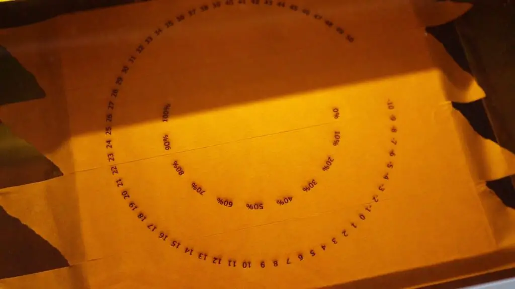
I started out by engraving and then cutting the gears. I always use masking tape over the MDF when engraving or cutting so that the smoke doesn’t mark the surface.
I then engraved and cut out the front panel, and finally cut out the remaining stand components.
Once all of the parts have been cut, you’ll need to remove the masking tape from them.
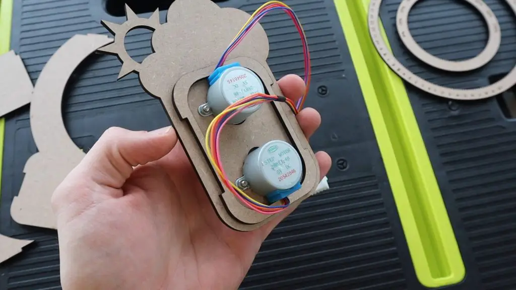
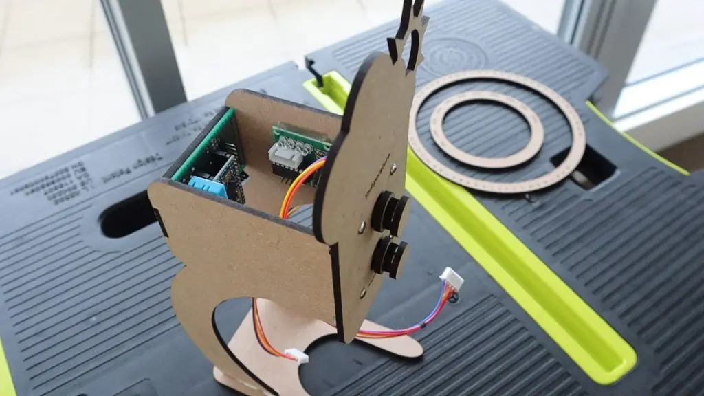
Installing The Stepper Motors
Next secure the two stepper motors to the front plate using two M3 x 10mm machine screws for each motor.
It’s a good idea to glue the stand support plate with the cutout for the motors to the back-side of the front panel before adding the motors, as it’s a bit easier than having to work around the motors later. It’s best to use wood glue to glue the MDF components together.
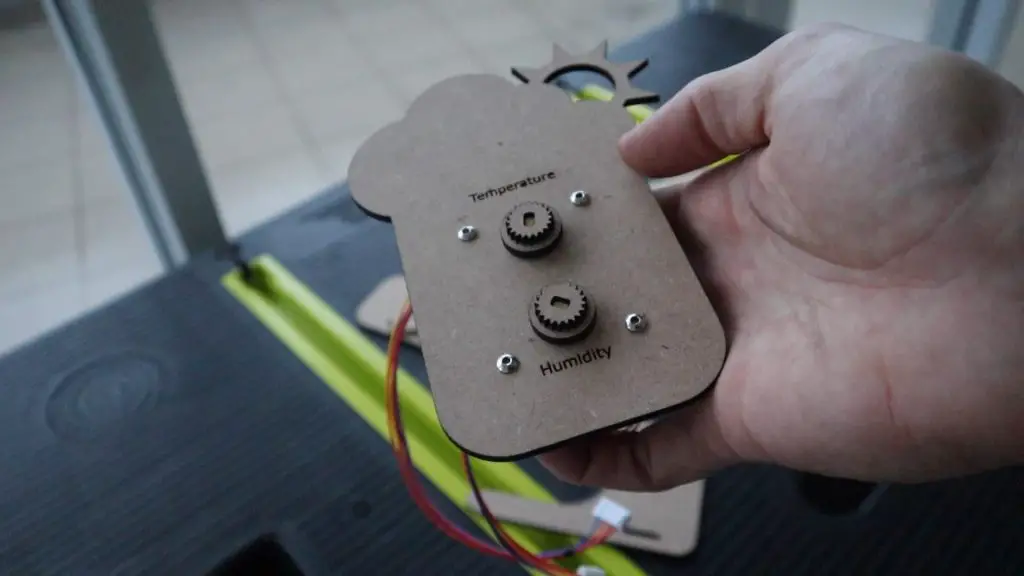
Next, you’ll need to assemble the gears.
Stack your gear pieces onto your servos with a drop of wood glue between each. Start with the disc with a hole in it and then the gear.
You’ll then need to add a small spacer between the gear and the front disc to create a bit of room for the gears to move freely. I used a flat washer for each of these. You could even use a small circle of thick card or plastic.
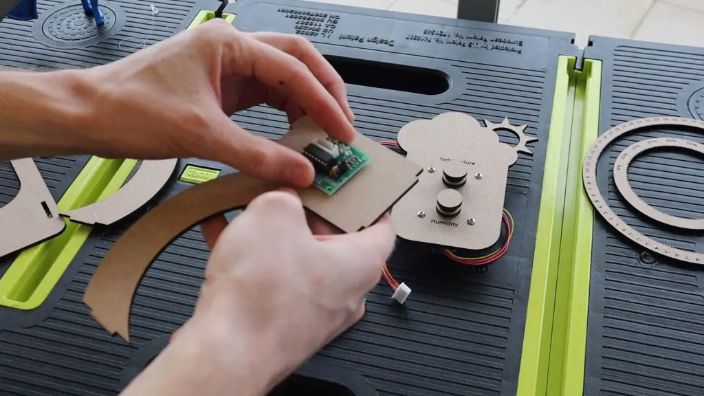
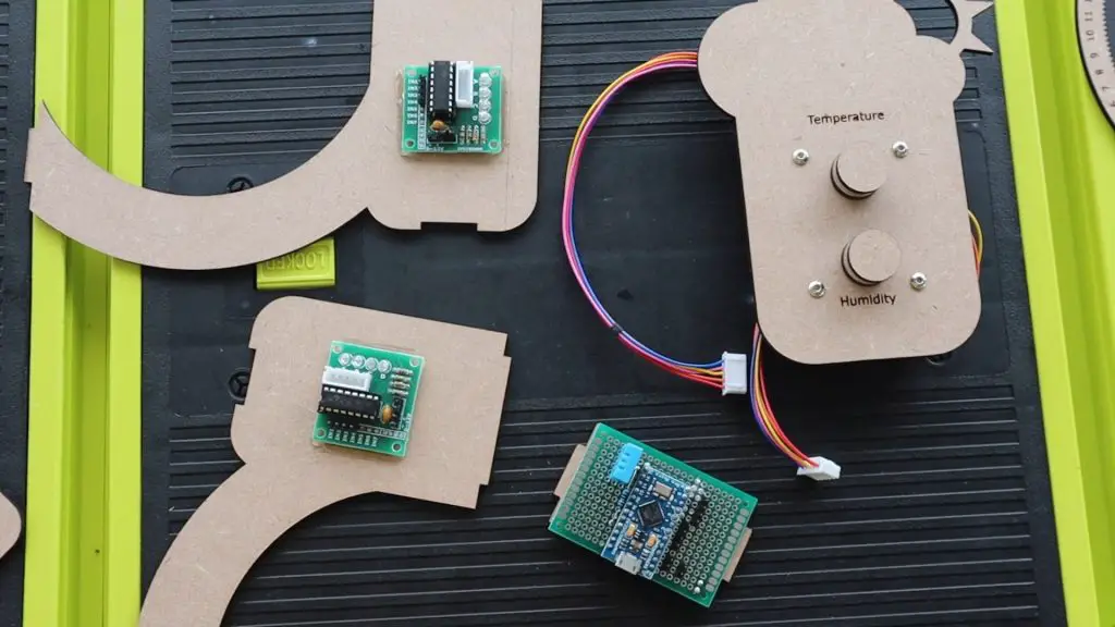
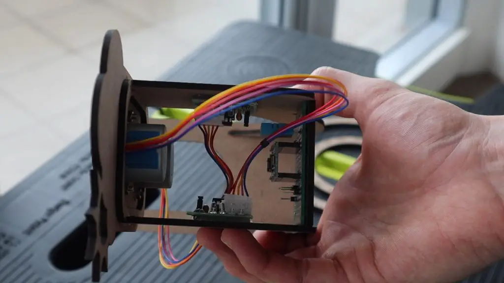
Assemble The Electronic Components
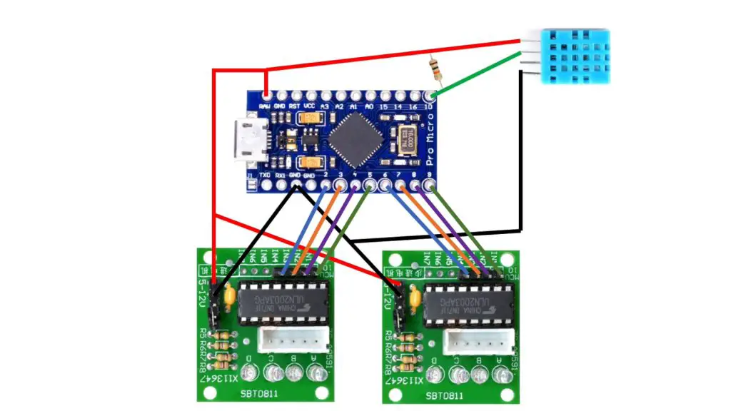
Here is a sketch of the connections between the Arduino and the DHT sensor and stepper motor drivers:
The circuit is quite simple and includes basic connections from digital IO pins 2 to 9 to the two stepper drivers and then a connection between the DHT11 sensor data pin and digital IO pin 10. You’ll also need to add your power connections to the sensor and stepper drivers as well as a 10k resistor between the connection to digital pin 10 and 5V.
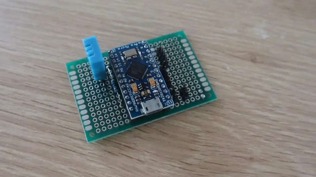
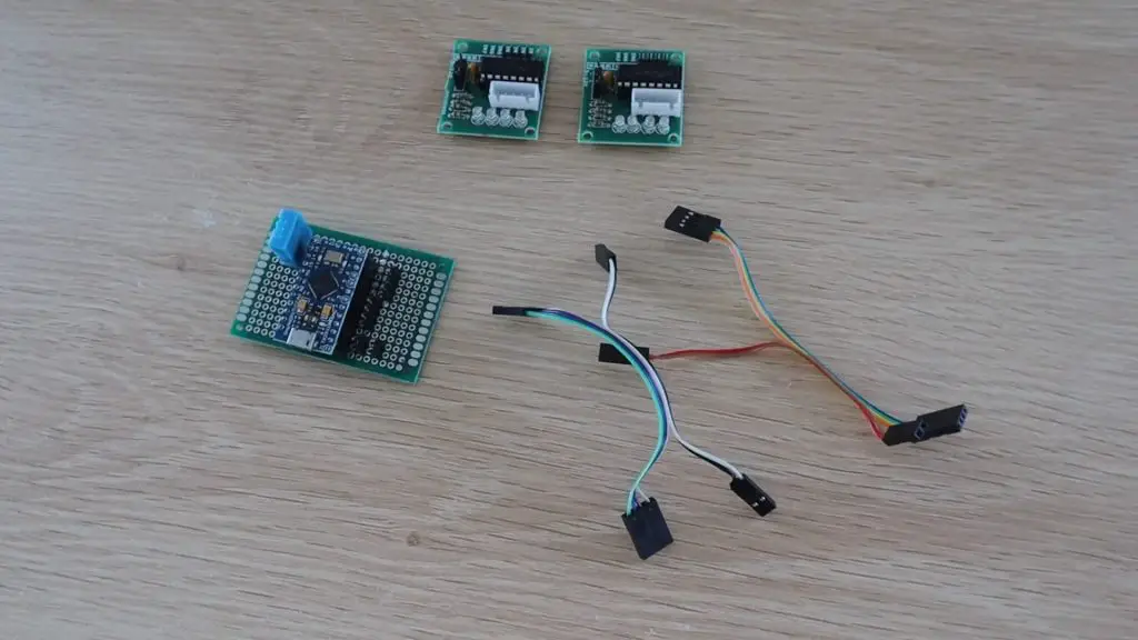
I assembled the header pin connections and DHT sensor onto a prototyping PCB so that the Arduino and stepper motor drivers could just be plugged into it.
I then made up some Dupont connector cables to connect the PCB and the stepper motor drivers. You can use jumpers or create your own header cables by soldering some ribbon cable to the female header pin connectors.
Now that the electronics are complete, let’s install them onto the MDF components and complete the assembly of the weather station.
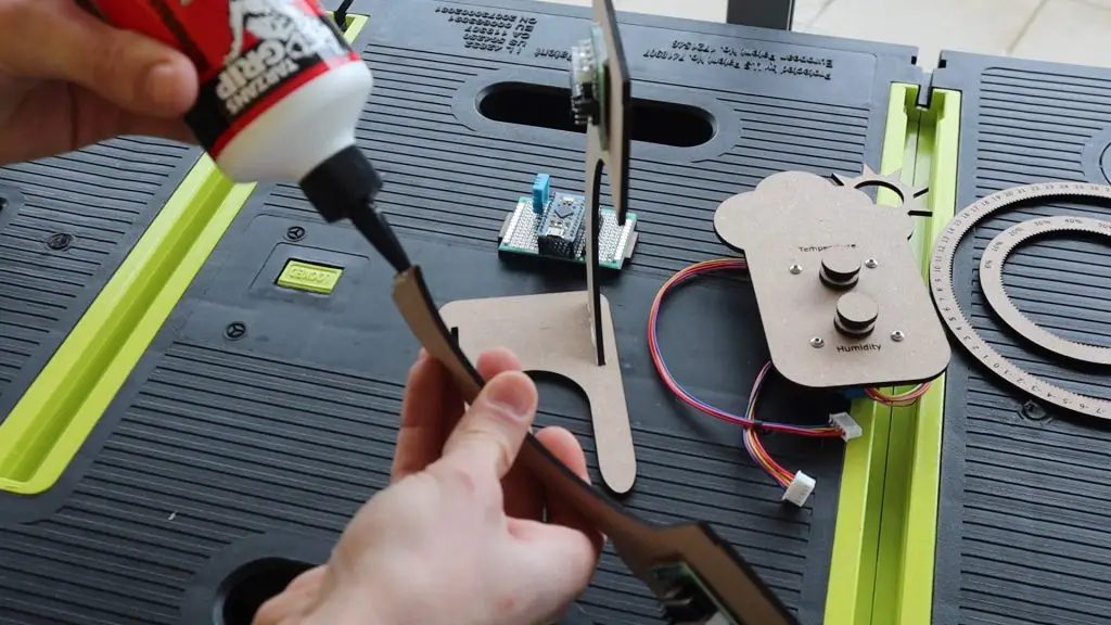
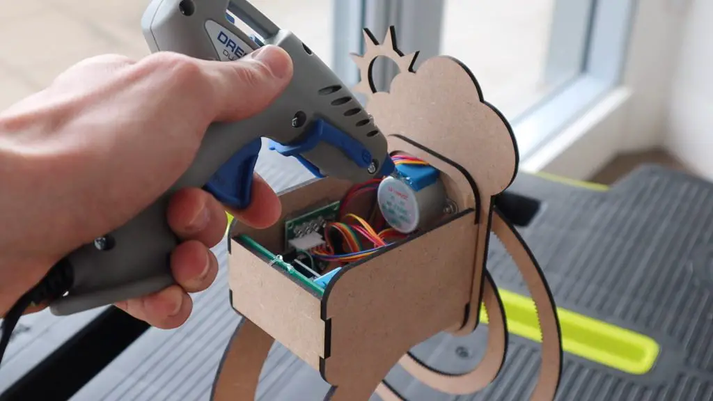
Complete The Assembly Of The Weather Station
I used a glue gun to glue the Arduino PCB to the back plate of the weather station and the two stepper motor drivers onto the two side stand pieces.
Once you’ve got the electronics glued into place, we can assemble the rest of the weather station using wood glue.
Glue the two legs into the base and then add the front plate onto the legs.
Finally, glue the back plate into place and allow the glue to dry. Make sure that the Arduino’s micro USB port is facing towards the base of the weather station.
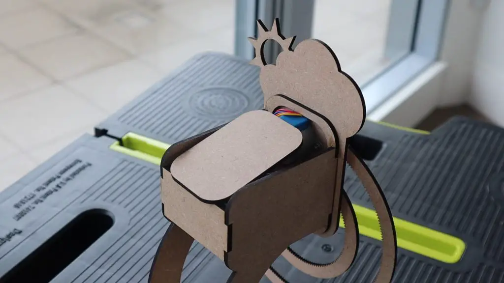
Once the glue is dry, plug the stepper motors into the drivers and then connect the drivers to your Arduino using the cables you’ve made up.
Try to tuck the cabling in so that it doesn’t hang out of the bottom or protrude out of the top of the back area.
If you’d like to close up the top, use the piece cut out of the support stand plate. Don’t glue this into place until you’ve tested out your stepper drivers and connections as you may need to access the cables again to make changes.
Plug your micro USB cable into the bottom of your weather station and you’re now ready to upload the code.
Programming Your Hanging Gear Weather Station
Now that your hanging gear weather station is built, you need to program the Arduino to take temperature and humidity measurements from the sensor and move the stepper motors to display the measured values.
Here is the sketch:
//The DIY Life
//Weather Station
//28 July 2020

#include "DHT.h"          //Import the required libraries for the sensor

#define DHTPIN 10         //DHT Sensor Pin
#define DHTTYPE DHT11     //DHT 11 Temperature & Humidity Sensor
DHT dht(DHTPIN, DHTTYPE);

int tempPins[] = {2,3,4,5};   //Define the temperature motor pins
int humidPins[] = {9,8,7,6};  //Define the humidity motor pins

int temp = 25;                //Create a variable for the temperature
int stepsPerDeg = 338;        //The number of motor steps for 1 degree celcius on the gear
int humid = 50;               //Create a variable for the humidity
int stepsPerPer = 69;         //The number of motor steps for 1 percent on the gear
int movementSpeed = 30;       //The motor movement delay in milliseconds

void setup(void)
{
  Serial.begin(9600);         //Used initially to display measured values
  for (int i = 0; i <= 3; i++)
  {
    pinMode(tempPins[i], OUTPUT);   //Assign the motor pin functions
    pinMode(humidPins[i], OUTPUT);
  }
  dht.begin();                      //Connect to the DHT Sensor
  delay(2000);
}

void loop(void)
{
  float startTime = millis();
  int newTemp = dht.readTemperature();   //Read in the current temperature
  int newHumid = dht.readHumidity();     //Read in the current humidity
  Serial.println(newTemp);               //Display values on serial monitor
  Serial.println(newHumid);
  int tempDiff = newTemp-temp;           //Calculate the difference between the actual indicated values
  int humidDiff = newHumid-humid;
  temp = newTemp;                        //Set the current values to the updated values
  humid = newHumid;
  int tempSteps = abs(stepsPerDeg*tempDiff);  //Calculate the number of motor steps to get to the new value
  int humidSteps = abs(stepsPerPer*humidDiff);
  bool tempDir = 0;                      //Create variables for the motor movement directions
  bool humidDir = 0;
  if (tempDiff < 0)                      //Set the motor movement directions
  {
    tempDir = 1;
  }
  if (humidDiff < 0)
  {
    humidDir = 1;
  }
  moveMotors(tempSteps, tempDir, humidSteps, humidDir);   //Call the moveMotors function to move the two motors
  float endTime = millis();
  if (endTime-startTime < 5000)    //Wait at least 5 seconds between updates
    delay(5000-(endTime-startTime));
}

void moveMotors(int tempSteps, bool tempDir, int humidSteps, bool humidDir)
 //Function to move motors
{
  for(int i=0; i<tempSteps ; i++)      //Move the temperature motor the required number of steps
  {
    static byte out = 0x01;
    if (tempDir)                       //Set the temperature motor direction
    {
      out != 0x08 ? out = out << 1 : out = 0x01;
    }
    else
    {
      out != 0x01 ? out = out >> 1 : out = 0x08;
    }
    for (int i = 0; i < 4; i++)        //Ring out the motor movement
    {
      digitalWrite(tempPins[i], (out & (0x01 << i)) ? HIGH : LOW);
    }
    delay(movementSpeed);              //Wait the delay time between steps
  }
  for(int i=0; i<humidSteps ; i++)     //Move the humidity motor the required number of steps
  {
    static byte out = 0x01;
    if (humidDir)                      //Set the humidity motor direction
    {
      out != 0x08 ? out = out << 1 : out = 0x01;
    }
    else
    {
      out != 0x01 ? out = out >> 1 : out = 0x08;
    }
    for (int i = 0; i < 4; i++)        //Ring out the motor movement
    {
      digitalWrite(humidPins[i], (out & (0x01 << i)) ? HIGH : LOW);
    }
    delay(movementSpeed);              //Wait the delay time between steps
  }
}
We start by importing the library for the DHT11 sensor. We then assign the sensor pin and create a sensor object using the correct sensor type.
We then assign the pins for the two stepper motor drivers.
We then create variables for the temperature and humidity measurements as well as two values for the number of steps the stepper motors need to make in order to move the temperature gear by one degree and the humidity gear by one percent.
The values set as the temperature and humidity here are the initial values that should be set when you place the gears onto the motors before powering up the weather station. The gears will then move to the correct measured values from these starting values. You can make adjustments to these values if you’d like to more accurately suit the measured values you expect.
We also have a motor movement speed. The speed is essentially a delay between steps in milliseconds, so a higher value is a slower speed.
In the setup function, we start serial communication, which is used to see what the actual measured values are in order to compare them with what is displayed during the initial calibration and setup.
We then assign the stepper motor driver pins numbers and then connect to the DHT sensor.
In the loop function, we record the start time for the cycle. Then take a new temperature and humidity measurement. We display these on the serial monitor and then calculate the difference in temperature and humidity from the last measurements taken. We can then replace the old measurements with the new measurements.
We then take the differences and convert them into a number of steps required to get to that indication on each gear, then set the directions of motor movement and then call a function called moveMotors to move each of the motors the required number of steps and in a particular direction.
Finally, we check to see that at least five seconds have passed between each update. If not, because neither gear moved in that cycle, the delay waits out the additional time until 5 seconds have passed. This delay can be increased or decreased depending on how quickly your environment is likely to change. If you’re in a large room of outdoors then you could change the update time to be every couple of minutes rather.
The move motors function just rings out the movement of each motor by the required number of steps and in the required direction, with a short delay between each pulse to slow the motors down.
That’s the code, now let’s see how it works.
Setting Up And Using The Weather Station
Before you upload the code, place the two gears onto the motors, setting them to indicate the values set up initially in the code, these were 25°C and 50% humidity in my code.
You can then upload the code.
If you open up your serial monitor, you’ll see the first measurement taken by the sensor and the motors will then start moving the gears to get to these values from the initial values. Mine were 22°C and 62% relative humidity.
Once the movement finishes, you should see a second set of values and the gears may move again.
It usually takes a couple of minutes for the sensor readings to stabilise and you’ll then get move consistent data and less movement of the gears.
Calibrating The Gear Movement
If you notice that your displayed values are not the same as those shown in the serial monitor, first check that your motor movement directions are correct, then check your initial values are correct. If both of those are correct, you may need to make adjustments to the number of steps per degree or percent values in order to calibrate your weather station.
To do this, set the gear you’re calibrating to a known position, say 0°C or 0% humidity, and then set the corresponding motor to move a certain number of steps, the more the better. I’d suggest using around 5000 steps for each as a starting point. Wait for the motor to move the set number of steps and then make a note of the finishing position. In order to calculate the stepsPerDeg or stepsPerPer, simply divide the total number of steps moved by the motor by the number of degrees or percent moved on the gear.
For example, if I set my temperature motor to move 5000 steps and it moved from 0°C to 14.8°C, then my stepsPerDeg value should be 5000/14.8 = 338. Meaning that the motor needs to move 338 steps to move the temperature gear by one-degree celsius.
That’s it! Your weather station can now be set up on your desk or shelf to indicate the current temperature and humidity.
Let me know in the comments section if you’ve built a weather station before and what you used to display the values.
Do you often forget to water your indoor plants? Or perhaps you give them too much attention and over-water them. If you do, then you need to make yourself a soil moisture monitor. This Arduino based, battery-powered monitor uses a captive sensor to measure the moisture level of the soil it is stuck into and then flashes LEDs and provides an OLED display readout telling you whether you’re over or under watering your plant.
Two potentiometers on the monitor allow you to set a maximum and minimum moisture level which then activates either the red LED, to indicate a low moisture level, to tell you that you need to water your plant, or the yellow LED on a high moisture level, to tell you that you’re overwatering your plant. You can also push the button next to the display to turn on the OLED display and to see the exact moisture level as well as the two set points.
Here’s a video of the build and the monitor being turn on and used, read on for the step by step instructions to build your own.
What You Need To Build Your Own Soil Moisture Monitor
I started out by designing the circuit, with the intention of making it into a PCB. There are quite a few external components to this monitor, so a PCB helps make assembly easy, with fewer loose wires, and makes the monitor into a more robust device that can be mounted onto the moisture sensor spike.
If you don’t want to build the monitor onto a PCB, it can also be easily assembled onto a breadboard and you can just use the lead included with the capacitive moisture sensor to connect the sensor to the breadboard.
I ordered the boards from PCB Way, which charges only $5 for 5 basic PCBs up to 100 x 100mm. They were manufactured and shipped out just three days later and arrived in less than a week.
I was also really happy with the quality of the boards, they’re a lot better quality than the typical cheap PCBs available online.
I’d really recommend trying them out for your own PCBs. I’ve put links to my PCB files which you can order from PCB Way if you’d like to try build your own moisture monitor.
The board is designed for a 3.3V Arduino Pro Mini to be run on a single 18650 lithium battery, but you can also use a 5V Pro Mini, you’ll just need to use a higher voltage battery pack to supply the board and use 220Ω LED resistors.
If your Arduino Pro Mini came without the header pins attached, you’ll need to start by attaching them. Also, remember that this design needs the two analog pins A4 and A5 to communicate with the OLED display, so don’t forget to add these two pins as well.
Solder the components into place on the circuit board, paying attention to the orientation of the LEDs and the tactile push-button.
In order to connect the moisture sensor to your circuit board, you’ll need to remove the connector which comes pre-soldered onto the sensor. You can then add three male header pins and solder the sensor directly onto your circuit board.
Once you’re done, use some side cutters to clip the ends off of the header pins to make the board more compact.
Your soil moisture monitor is now complete and just needs a power source.
I powered my monitor using a single 18650 lithium cell mounted into one of these USB charging boards. You can use a different battery if you’d like or power your monitor using a USB charger or power bank.
Connect your battery pack or power supply to the power supply terminals on the side of the circuit board, paying attention to the polarity.
If you’re using a single battery, or a compact battery pack, try glue the battery to the back of the circuit board so that it’s all one unit.
Programming Your Monitor
To program the Arduino Pro Mini, you’ll need to use a USB programmer. Plug jumpers between the programmer and the header strip on the circuit board, making sure that the programmer pins go to the correct Arduino pins and that you use the correct Vcc voltage pin on the programmer to suite the board you are using, 3.3V for the 3.3V Pro Mini and 5V for the 5V Pro Mini.
You’ll also need to use the programmer when you’re using Serial communication to transmit the sensor values to your computer in order to calibrate your moisture monitor.
Here is the code:
//The DIY Life
//Michael Klements
//31 July 2020

#include <SPI.h>                                  //Import the libraries required for the display and low power mode
#include <Wire.h>
#include <Adafruit_GFX.h>
#include <Adafruit_SSD1306.h>
#include <LowPower.h>

#define SCREEN_WIDTH  128                         //OLED display width, in pixels
#define SCREEN_HEIGHT 32                          //OLED display height, in pixels

#define OLED_RESET     -1                         //Reset pin # (or -1 if sharing Arduino reset pin)
Adafruit_SSD1306 display(SCREEN_WIDTH, SCREEN_HEIGHT, &Wire, OLED_RESET); //Create the display object

#define statusLED 4                               //Define the LED & sensor pins
#define lowLED 5
#define highLED 6
#define sensorPin 10                              //Only used for the additional low power settings

#define dryCal 1000                               //Define the wet and dry calibration limits
#define wetCal 500

#define buttonPin 2                               //Define the button pin number

#define moisturePin A0                            //Define the analog input pin numbers
#define lowSetPin A1
#define highSetPin A2

int moisture = 0;                                 //Create variables for the analog inputs
int lowSet = 0;
int highSet = 0;

int cycleCount = 0;                               //Create a counter to flash the status LED

void setup()
{
  Serial.begin(9600);
  display.begin(SSD1306_SWITCHCAPVCC, 0x3C);      //Connect to the display
  display.clearDisplay();                         //Clear the display
  display.setTextSize(1);                         //Normal 1:1 pixel scale
  display.setTextColor(SSD1306_WHITE);            //Draw white text
  display.setCursor(10,5);                        //Display splash screen
  display.print(F("The DIY Life"));
  display.setCursor(10,15);
  display.print(F("Soil Moisture Meter"));
  display.display();
  delay(2000);
  display.clearDisplay();                         //Clear display
  display.display();
  pinMode(statusLED, OUTPUT);                     //Set the pin modes
  pinMode(lowLED, OUTPUT);
  pinMode(highLED, OUTPUT);
  pinMode(sensorPin, OUTPUT);
  pinMode(buttonPin, INPUT);
}

void loop()
{
  updateValues();                                 //Call the function to update the analog input values
  if (digitalRead(buttonPin) == HIGH)             //If the button is pushed
  {
    while(digitalRead(buttonPin) == HIGH)         //While the button stays pushed
    {
      display.clearDisplay();                     //Display the analog input values
      display.setCursor(10,3);
      display.print(F("Moisture: "));
      display.print(moisture);
      display.print(F("%"));
      display.setCursor(10,13);
      display.print(F("Low Setpoint: "));
      display.print(lowSet);
      display.print(F("%"));
      display.setCursor(10,23);
      display.print(F("High Setpoint: "));
      display.print(highSet);
      display.print(F("%"));
      display.display();
      delay(1000);                                //Wait 1000ms between each display update
      updateValues();                             //Get updated analog input values, allows pots adjustments to be seen
    }
    display.clearDisplay();                       //When button is released, clear the display to turn it off
    display.display();
  }
  if(moisture<=lowSet)                            //If the soil moisture level is low, flash the low LED
  {
    digitalWrite(lowLED, HIGH);
    delay(50);
    digitalWrite(lowLED, LOW);
  }
  if(moisture>=highSet)                           //If the soil moisture level is high, flash the high LED
  {
    digitalWrite(highLED, HIGH);
    delay(50);
    digitalWrite(highLED, LOW);
  }
  if(cycleCount>=5)                               //Every 5 cycles, flash the status LED and reset the counter
  {
    digitalWrite(statusLED, HIGH);
    delay(50);
    digitalWrite(statusLED, LOW);
    cycleCount=0;
  }
  LowPower.powerDown(SLEEP_8S, ADC_OFF, BOD_OFF); //Enter low power mode for 8 seconds
  cycleCount++;                                   //Increment the cycle counter
}

void updateValues ()                                              //Function to update the analog input values
{
  //digitalWrite(sensorPin, HIGH);                                //LOW Power Mode - Turn the moisture sensor on
  //delay(200);                                                   //LOW Power Mode - Wait for it to power up and stabilise
  moisture = map(analogRead(moisturePin),wetCal,dryCal,100,0);    //Read the soil moisture measurement
  Serial.println(moisture);
  //delay(50);
  //digitalWrite(sensorPin, LOW);                                 //LOW Power Mode - Turn the moisture sensor off
  lowSet = map(analogRead(lowSetPin),0,1023,0,100);               //Read in the low setpoint pot value
  if (lowSet>=highSet)                                            //Make sure that the low setpoint cannot be greater than the high
    lowSet=highSet-1;
  highSet = map(analogRead(highSetPin),0,1023,0,100);             //Read in the high setpoint pot value
  if (highSet<=lowSet)                                            //Make sure that the high setpoint cannot be less than the low
    highSet=lowSet+1;
}
We start by importing the libraries required for the OLED display and the low power mode. The library for low power mode is used to put the Arduino into a state where it uses less power than usual in order to prolong the battery life of the monitor.
We then set up the display parameters and create the display object.
We then define the LED and sensor PIN numbers. The sensorPin is only required for the additional low power settings which are explained later on.
We then have the wet and dry calibration set points, the button pin and then the analog input pin numbers.
Finally, we have variables to read in the analog inputs and a counter which is used to flash the status LED every 5 cycles.
In the setup function, we start Serial communication, which is used during setup to get the raw sensor values to set up the calibration, then connect to the display and show a splash screen. After two seconds of displaying the splash screen, we clear the display and then define the pin modes.
The loop function is quite simple. We call a function called updateValues to update the sensor and potentiometer readings, then check if the button has been pushed. If the button has been pushed, we then have a while loop which runs until the button is released again, which displays the soil moisture reading and potentiometer set points on the OLED display and updates the displayed values once every second.
When the button is released, the OLED display is turned off again to save power and the LED set points are then checked. If the soil moisture level is higher than the high set point, then the high LED is flashed and if the soil moisture level is lower than the low set point then the low LED is flashed.
We also have an if statement which flashes the status LED every 5 cycles or around 40 seconds to tell us that the monitor is still on. This is useful if you remove the Arduino’s power LED, are described in the additional low power settings, in order to further prolong battery life.
We then put the Arduino into a low power sleep for 8 seconds in order to save battery power and then increment the cycle counter.
The update values function reads in the soil moisture level and maps the reading between the two calibration values to a moisture level between 0 and 100%.
We also read in the two potentiometer set points and map them to a 0 to 100% range and have checks to ensure that the low set point can’t be set higher than the high set point and that the high set point can’t be set lower than the low set point.
Additional Low Power Settings
You’ll notice that there are a couple of lines which have bee commented out and some notes mentioning some further low power settings.
The current setup without any code or hardware modifications draws around 8-10mA. This means that a 4200mA battery will last around 20 days before needing to be recharged.
This can be extended by connecting the Vcc pin on the sensor to the Arduino’s digital IO pin 10 so that the sensor is only turned on during readings.
The sensor alone draws about 5mA, so turning it off for 8 seconds between readings dramatically increases the battery life. This will slow the code down a bit too as you’ll need to wait for the sensor to startup and stabilise before getting meaningful readings from it. This won’t really affect the normal operation of the monitor but will be noticeable when the OLED display is on, as you’ll need to wait longer for readings to update.
Another thing to do to further improve the battery life is to physically remove the Arduino’s green power LED or cut through the PCB trace to it to turn it off. This reduces another 2-3mA.
Doing both of the above modifications will allow this monitor to run for around 50-60 days on a single charge.
Using The Soil Moisture Monitor
When powering the soil moisture monitor on, you should first see the splash screen and then the display should turn off.
Once off, you can push the button and then wait a few seconds for it to finish the sleep cycle and then turn the display on. You can then see the actual measured moisture level and the two set points.
Calibrate The Wet & Dry Levels
Before you get meaningful information from the monitor, you’ll need to calibrate the wet and dry limits and update the values in the code.
Use the USB programmer and your Serial monitor to display the raw sensor values being read on the analog input. Start by taking readings in dry air and then in glass or jug of water, making sure that you don’t submerge any of the components. Use the maximum and minimum values displayed as the two calibration limits in the code.
Try The Monitor Out
Once you’ve updated the calibration limits, you should be getting more meaningful results from your monitor. You can see the moisture level go up if you put your hand around the sensor.
Use a screwdriver to set the high and low setpoints on the two potentiometers.
You’ll notice that you can’t set the high potentiometers lower than the low setpoint and likewise, you can’t set the low setpoint to be higher than the high set point.
Stick the sensor into the soil in your indoor plant, making sure that the soil does not touch the electronics, and then leave it for a few seconds to stabilise.
You should then get a soil moisture reading and you can start setting the correct set points depending on the type of plant you have. This may require some trial and error in the beginning as certain plants like more water than others.
I also added a simple acrylic faceplate to screw over the PCB to protect the electronic components from leaves and water droplets
Have you tried making your own soil moisture monitor? Let me know what you built and how you used it in the comments section below.