I found an iPhone conversion kit online for $35 to convert an old iPhone 6 to a 2020 model iPhone SE lookalike. The front of both iPhones look virtually identical, so this kit changes the back of the iPhone to a glossy black finish (white is also available) like the glass back on the 2020 iPhone SE. It also changes the shrouding around the camera lens to be a bit bigger like the newer model iPhones.
This upgrade doesn’t change any of the iPhone’s functionality, so you don’t get any performance benefit, you still won’t have wireless charging and you will still have the headphone jack.
The kit didn’t come with any instructions and there were a couple of things to look out for in doing the conversion, but I managed to get all of the components swapped over to the new body without and issues and it looks pretty good once it’s done. I’m not sure how long this body will last though as it is mostly plastic, not aluminium like the original and I’m not convinced that the glossy back is actually glass.
Here’s my video of the swap over:
I now have an iPhone 6 which looks like a 2020 model iPhone SE, and it only cost $35.
If this is something you are interested in doing, here are some tips to help you out with the conversion:
Make sure that you keep your screws really well organised. There are a number of different size and length screws, even on the same components. Make sure that you know which one goes where or you’ll have an almost impossible task in putting it back together again.
Be extra careful when removing the ribbon cables which are stuck to the iPhone body, it is really easy to tear them if you use too much force. I found that using a plastic spudger to gently pry them up worked well.
Remember to move the metal contacts across to your new buttons if yours don’t come with them. This is easy to miss and you’ll then land up with buttons that don’t work. It’s also a mission to add them afterwards, you’ll basically need to disassemble the whole phone again.
If your iPhone is old, this is a good time to replace the battery as you’ll be removing the old one anyway.
If you enjoy tinkering with electronics and building your own Arduino and Raspberry Pi based projects then you’ve likely run into the question of how to power your project if you want it to be mobile and not plugged into an outlet somewhere. Batteries are the obvious answer, but standard AAs don’t last very long and lithium-ion battery packs can be a hassle to wire up, charge and keep balanced.
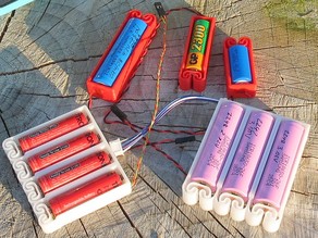
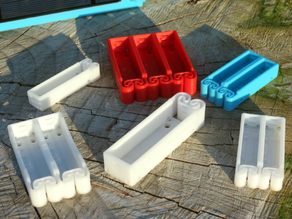
My favourite solution is to use 18650 lithium-ion cells in a 3 cell 3D printed holder. These batteries offer a relatively high storage capacity and are affordable and widely available. They can also be easily taken out of the battery holder and safely charged in a plug-in wall charger.
Having 3.7 cells means that for most applications, you’ll want to use 3 cells to get 11.1V, as 12V is commonly recommended for DC motor and stepper motor drivers, and they’ll usually handle 4 to 8A. Your Arduino will be fine running at 11.1V and you can also get an inexpensive DC to DC converter to step the voltage down and regulate the supply for your Raspberry Pi.
Be careful when using batteries for your Raspberry Pi projects, especially for things like unattended solar-powered weather stations as repeated low voltage related shutdowns without any protection can damage your Pi or corrupt the memory card.
They’re 3D printed and offer cell configurations in 1 to 4 cells. It’s recommended that you print them using ABS filament to give the plastic springs some flexibility. The contacts can be made by twisting and soldering a short length of uninsulated wire or using some copper strips. Each holder also has a number of holes for mounting screws to secure it to your project or housing.
It’s also quite easy to add solar charging to these batteries, the perfect solution for long term weather station or data logging projects. There are a number of small charge controllers available for these batteries, so you’ll just need to integrate one into your charging circuit.
If you’re interested in batteries, did you know that you can recondition your old lead-acid batteries rather than replacing them?
What do you use to power your mobile Arduino and Raspberry Pi projects? Let me know in the comments section below.
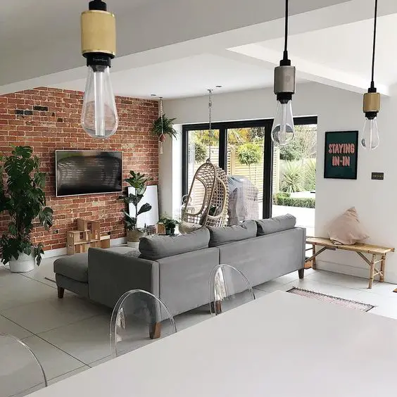
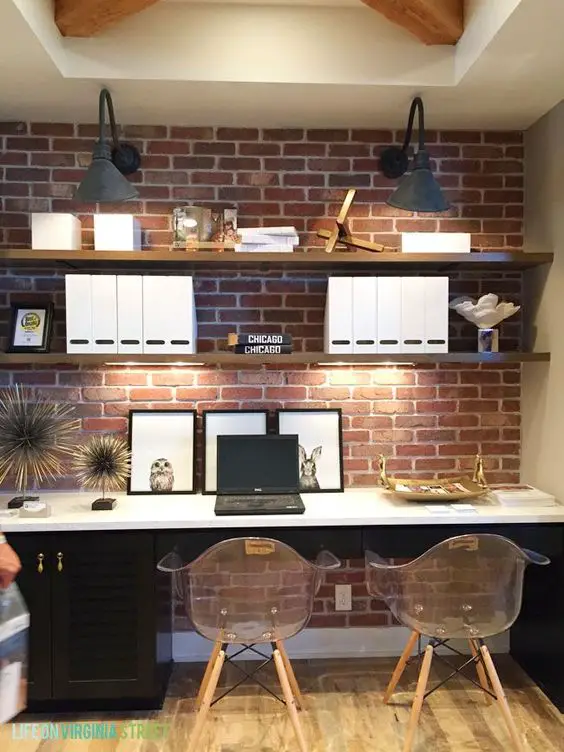
Exposed brick is rapidly becoming a popular home and business design trend and it’s easy to see why. In the right quantity and setting, it looks fantastic and it requires little to no maintenance. Fortunately, you don’t have to renovate a 19th century home or apartment to get the look either, there are loads of modern panels, veneers and even stick-ons which can be used to create the perfect feature wall.
Here are some of our favourite ways to incorporate exposed brick into your next home renovation project.
A statement wall in a hallway or room is one of the easiest and cheapest ways to incorporate exposed brick into your home. The colours in the brick generally bring enough colour into a room to work well with whites, greys and beiges.
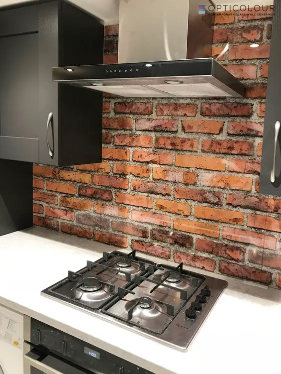
A splashback which doubles up as a feature wall in your kitchen is easy to keep clean and compliments your neutral countertops. Make sure that you get it properly sealed so that it’s easy to clean any cooking splashes and spills.
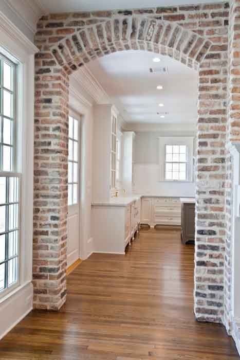
If you’ve already got an archway built into your home as a room or hallway divider, adding some brick veneers in the correct places make for an amazing feature.
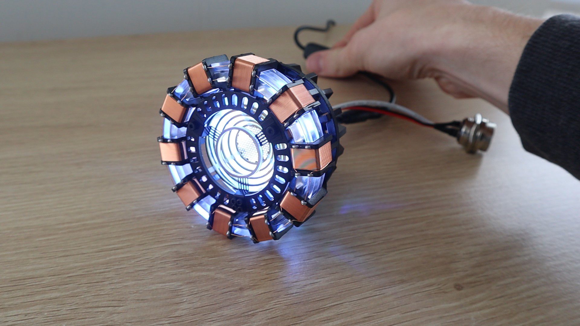
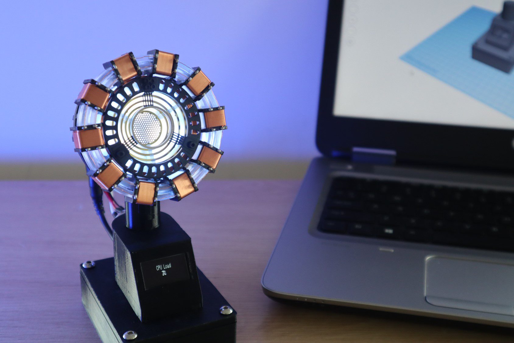
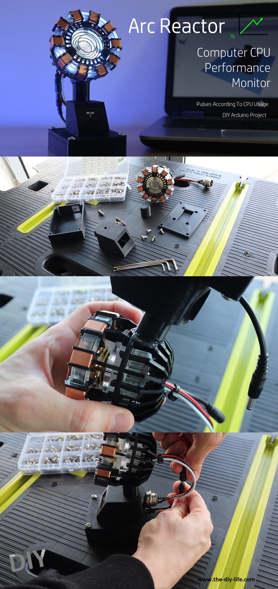
In this project, I’m going to be showing you how to turn one of these popular DIY arc reactor kits into a useful Arc Reactor CPU performance monitor for your computer. It plugs into one of your computers USB ports and displays your CPU performance on the OLED display and the arc reactor pulses according to your CPU usage, increasing the pulse frequency with an increased CPU load.
I started out by assembling an Arc Reactor kit, which has a built-in USB powered LED light and that got me thinking of a way to turn it into something useful for my desk. I initially thought about using an Arduino to make the LED pulse as some sort of readout or indication. This lead me to my computers CPU performance and I then decided to add the OLED display for a more accurate readout as well.
The arc reactor LED and OLED display are powered by an Arduino Uno in the base, which receives updates on the computers CPU usage every two and a half seconds and adjusts the pulse duration accordingly.
On the computer’s side, a python script reads the CPU performance data from a Hardware Monitoring application and posts this data to the Arduino through a serial communication port.
The device doesn’t need any external power, it is powered by the USB port as well.
Here’s a video of the build and the Arc Reactor in use, read on for the full step by step instructions as well as the code and print file downloads.
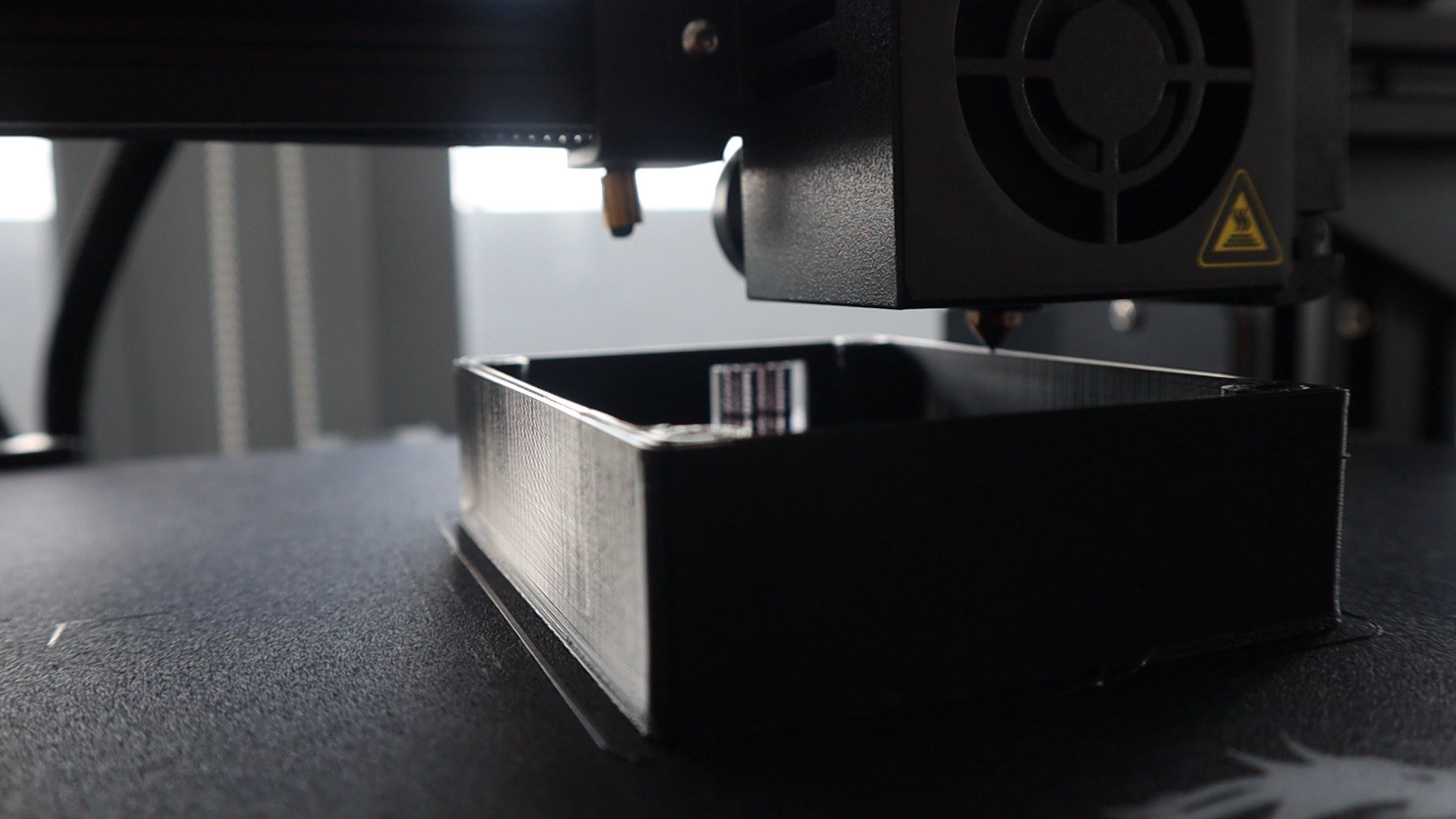
You’ll also need to 3D print the components for the stand. If you don’t have a 3D printer and you enjoy DIY projects and building things, you should really consider getting one. They’ve become a lot more affordable and really expand your workshop capabilities.
How To Build Your Own Arc Reactor CPU Performance Monitor
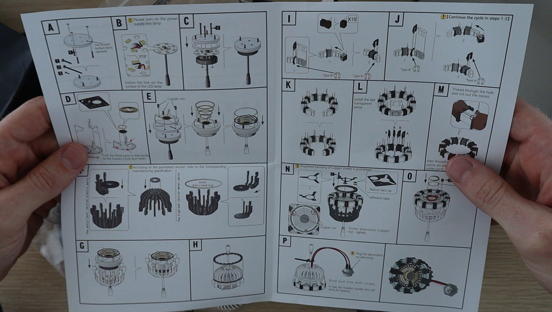
I’ve split the build process up into a couple of steps to make it easier to follow. We’ll start by assembling the Arc Reactor (with is done according to the enclosed instructions), then solder the electronics, then assemble the base and finally upload the sketch and run the Python script.
Assemble The Arc Reactor
Theses Arc Reactor kits have been around for a couple of years and most of them are reasonably good quality, so you shouldn’t have any trouble following the enclosed instructions and assembling your reactor. There isn’t anything you need to modify or change during the build, you can even use one which is preassembled if you’ve got one you’ve already built.
Depending on your kit, it should take around half an hour to an hour to assemble. Some kits do require you to wind your own coils or trim off a lot of excess plastic which can be time-consuming.
Solder The Electronic Components
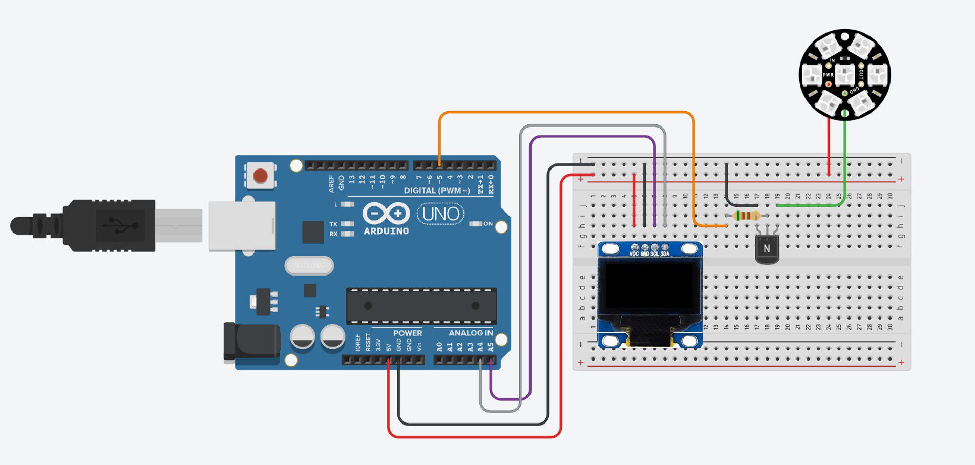
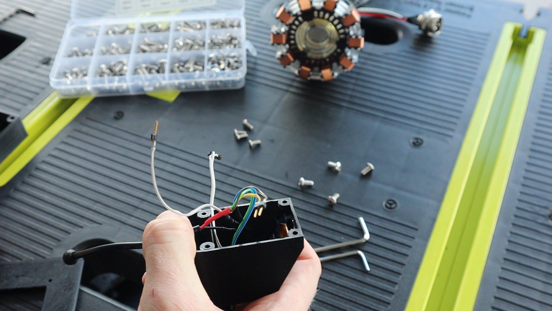
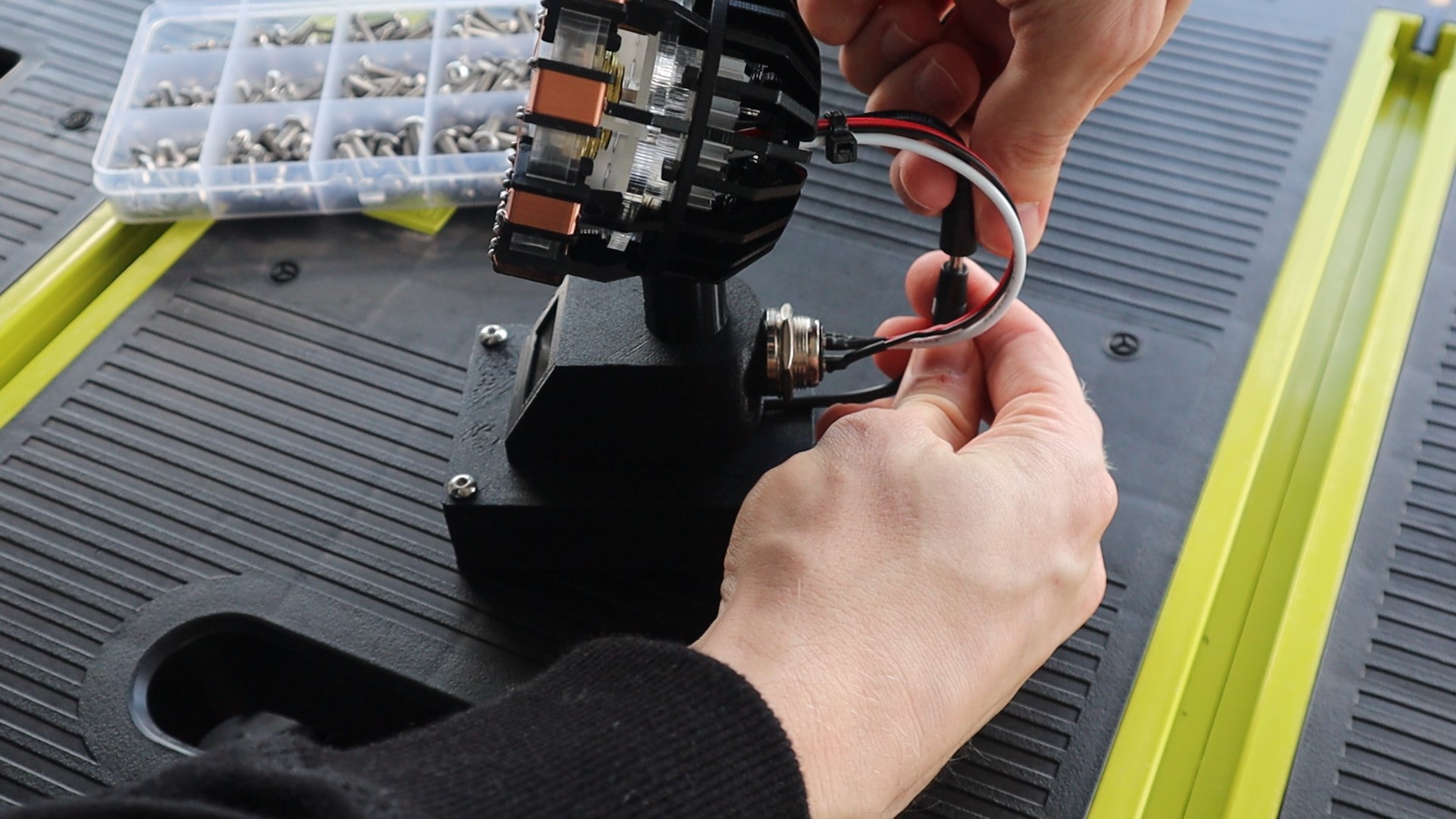
Before we assemble the base components, we need to make up the electrical circuit. The circuit for this project is quite simple and consists of an I2C connection between the Arduino Uno and the OLED display and then an NPN transistor connected to pin 5 of the Arduino to drive the Arc Reactor. The LED array on the Arc Reactor draws about 500 milliamps, which is too much to drive directly off of the Arduino. I added a 510Ω current limiting resistor onto the base leg of the transistor as well. I soldered this resistor directly onto the transistor and covered it with heat shrink tubing.
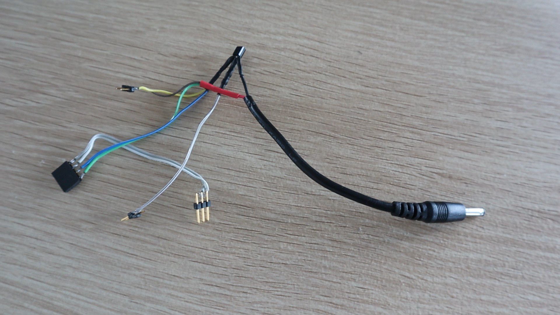
I connected the components using some coloured ribbon cable and header pins to plug into the Arduino and covered the exposed wiring on the transistor and plug with some heat shrink tubing.
Important Note – There seem to be two variants of these OLED displays available online and they look very similar. One version has the GND pin first and the other the VCC pin first. They do not have any reverse polarity protection, so if you connect them the wrong way around they instantly “pop” and have to be thrown out. Make sure that you check this before soldering the pin connector.
Print & Assemble The Arc Reactor Stand
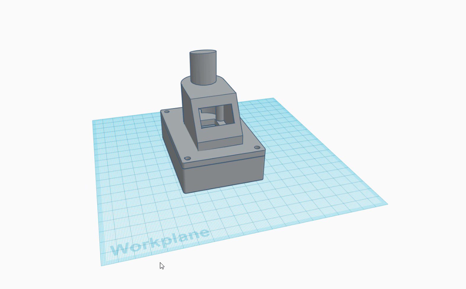
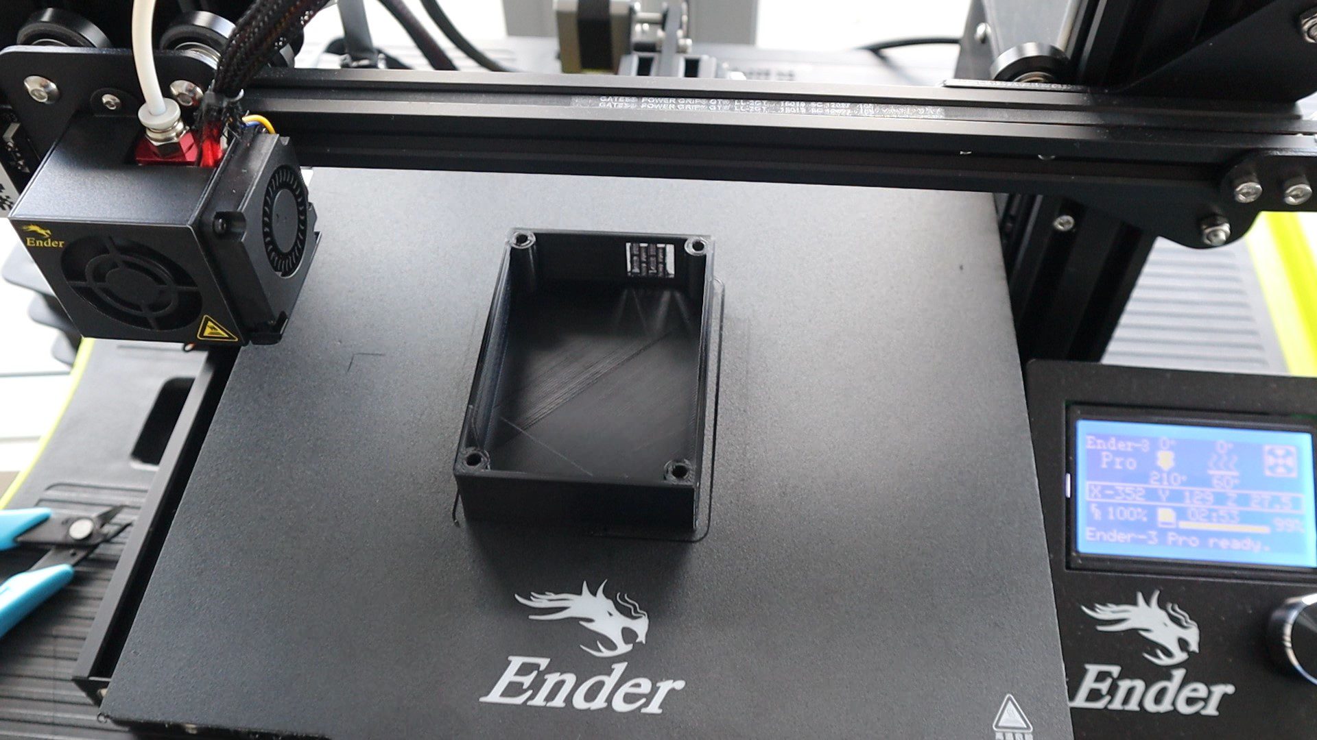
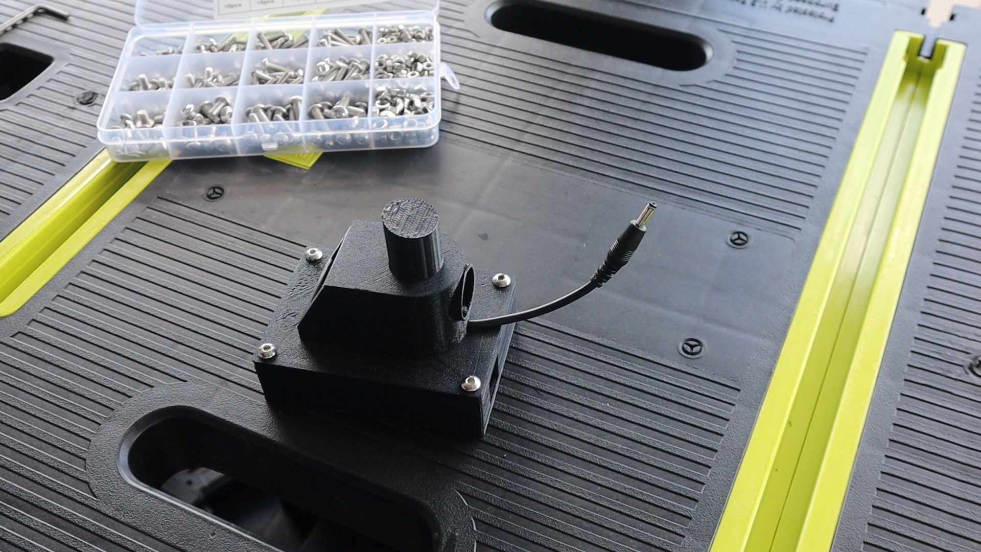
I designed four components which stack together with some hex head screws to make up the stand. There is a base compartment to house the Arduino. A cover to go over the base and connect to the display housing and then a post on top of the display housing to support the arc reactor.
I 3D printed the components using black PLA with a 15% infill. You could print the base out of a different colour as well, it would probably look great in silver or grey too. I usually try to hide the screws underneath the housing, but in this design I wanted the screws to be visible to add a bit of detail to the base.
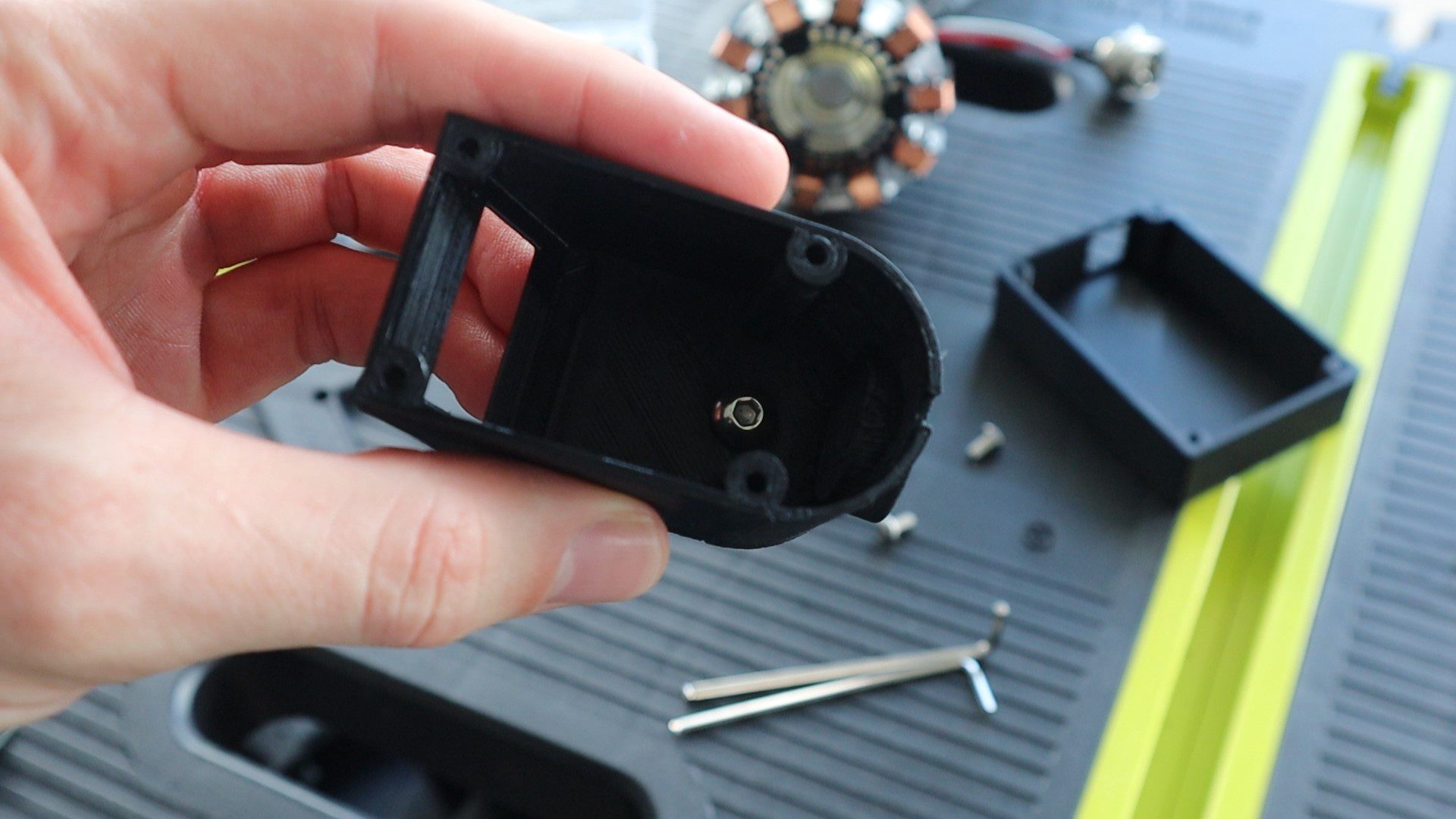
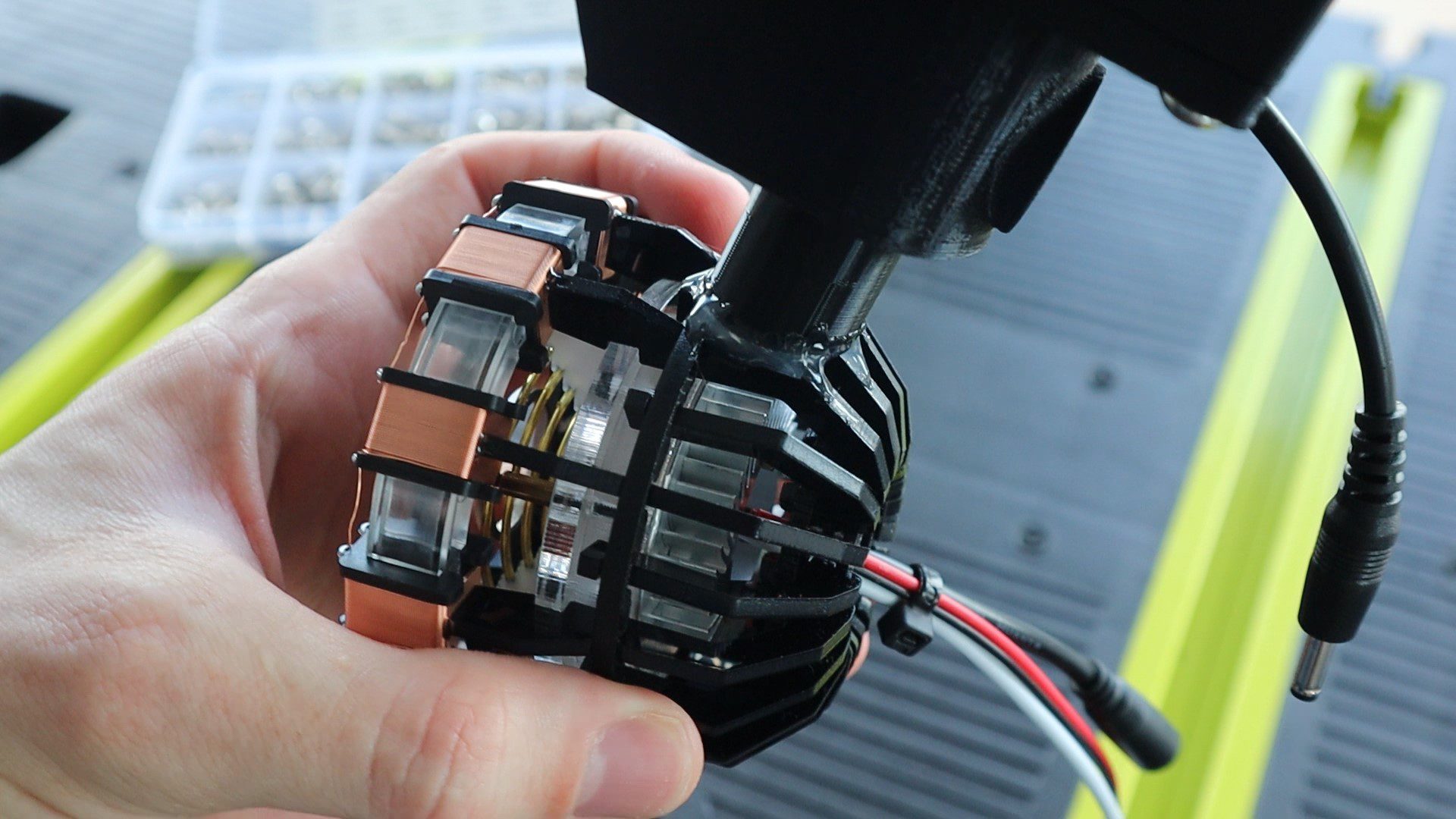
I’ve used a single M5 x 8mm hex head screw to secure the reactor post to the display housing. Make sure that the top surface of the post is angled to point the Arc Reactor slightly upwards, ie the highest point is in the front.
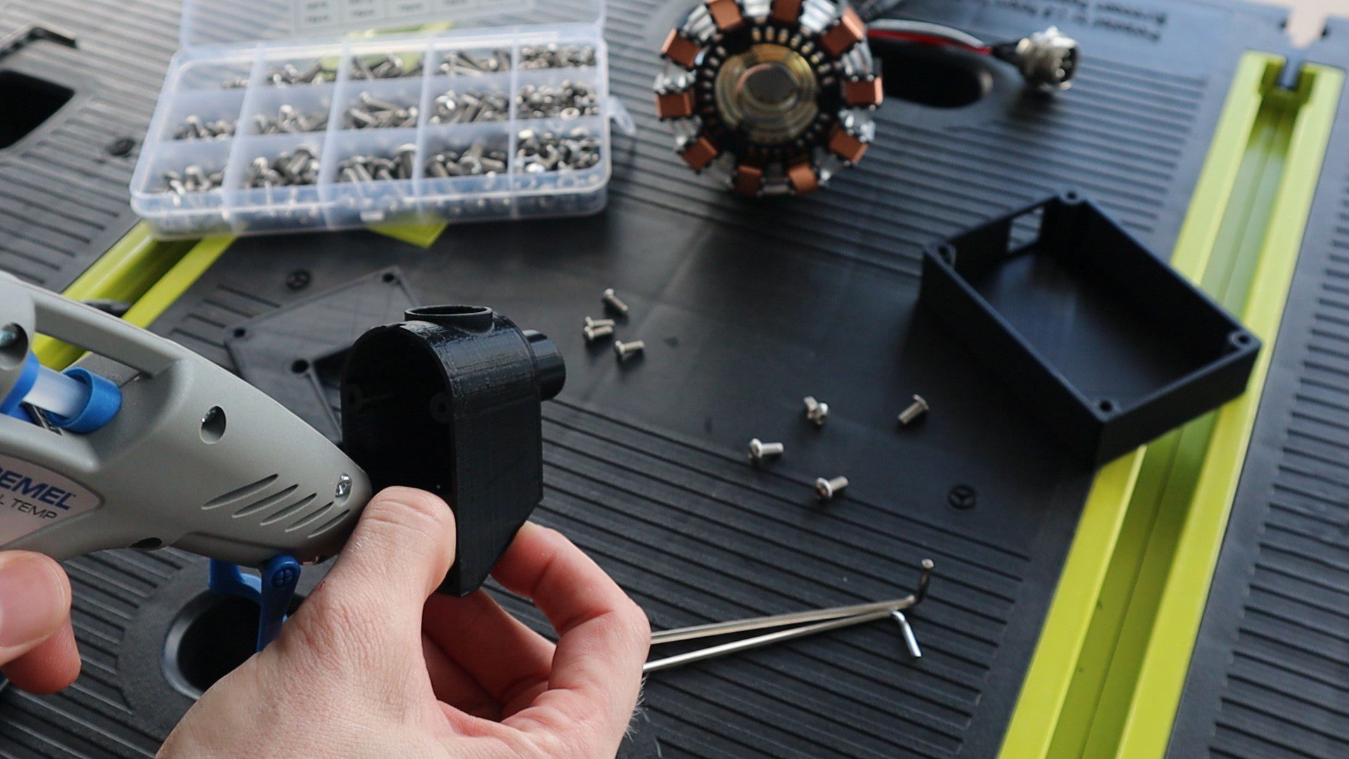
Then glued the OLED display into the housing using a glue gun.
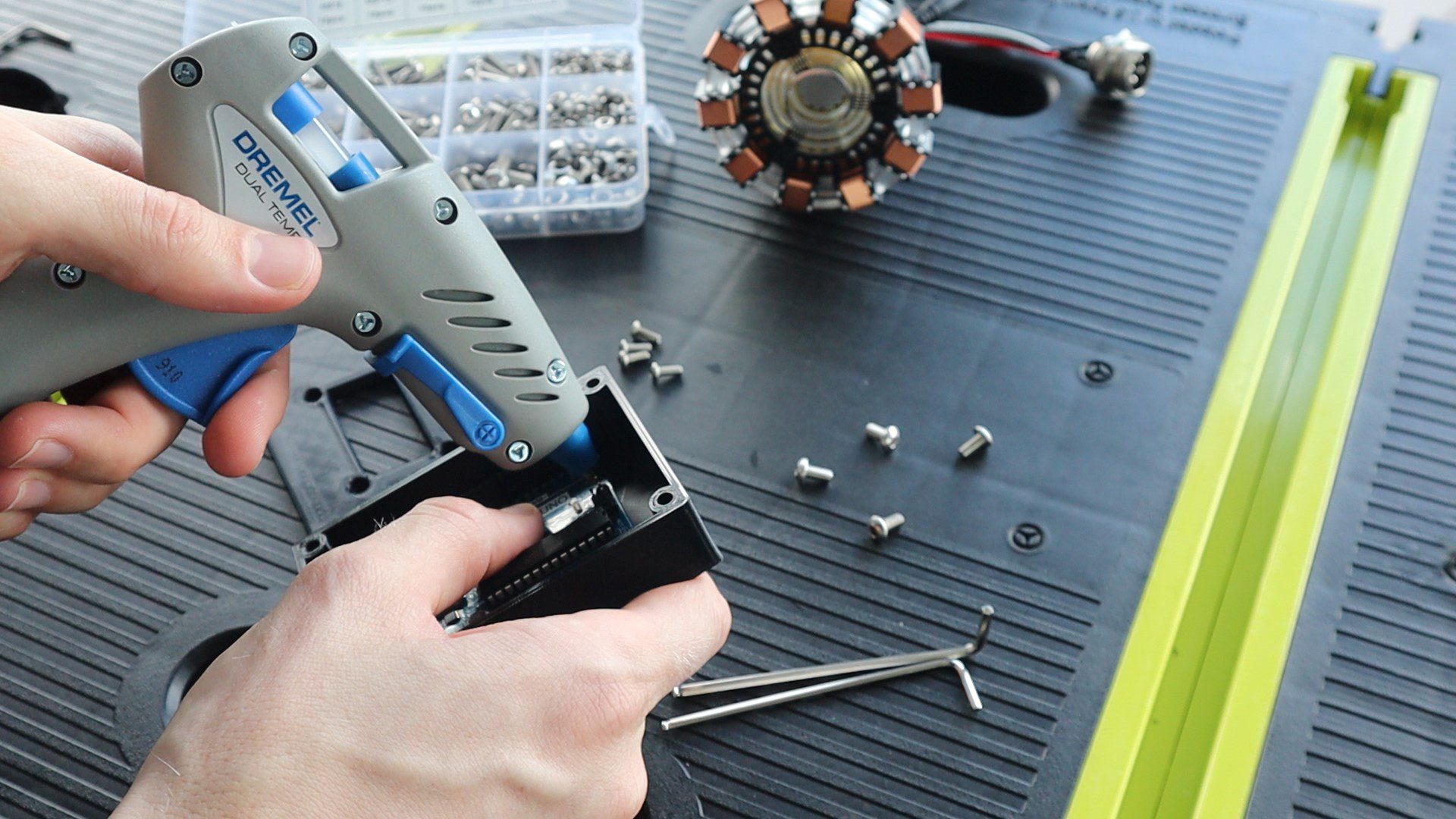
I then glued the Arduino Uno into the base, with the USB port lined up with the cutout.
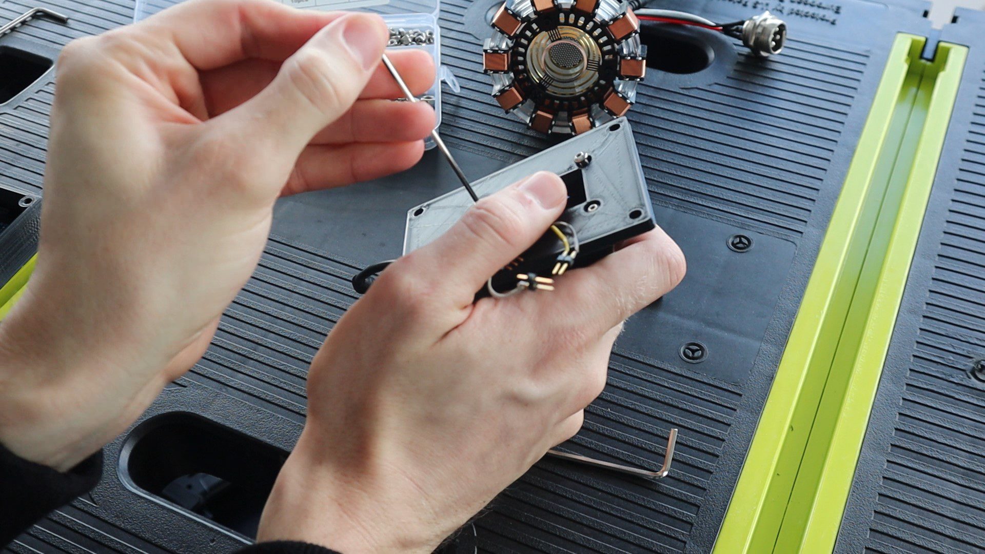
I then plugged the connector into the OLED display and attached the Arduino cover plate using four M3 x 8mm screws.
The cover then goes onto the base with four M4 x 8mm screws. I used M4 screws so that the heads are a bit larger and more visible on the base. You can switch these out for small M3 screws if you’d like, you’ll just need to modify the holes in the Arduino case to be slightly smaller.
I attached the arc reactor to the base using the glue gun again. There isn’t really a nice flat surface on the bottom of the arc reactor, so you need to build up the glue around the supports until it’s held securely in place.
Lastly, glue the arc reactor plug into the back of the stand. This is just a dummy plug but it looks better if it’s actually plugged into something. If you’d like to neaten up the wiring even further, you could remove the existing plug on the LED and solder this plug’s leads onto the LED instead and then buy a real socket to plug the arc reactor into.
Remember to also connect the power lead to the LED.
And that’s the Arc Reactor CPU Performance Monitor’s hardware complete, now we just have to program it.
Programming The Arc Reactor CPU Performance Monitor
There are three things you need to set up to get your CPU data to be sent to your Arduino, a source of the data on your computer, a script to read the source on your computer and send the data through a serial communication port to your Arduino and the code on the Arduino to read the data, recompile it and then update the display and reactor LED.
We’ll start off with the Arduino’s code.
Programming The Arduino Uno
The Arduino’s code is fairly simple thanks to the OLED displays libraries. Most of the code is actually dedicated to turning the data received through the serial communication port back into usable data.
Let’s have a look at the code:
//Michael Klements
//The DIY Life
//Arc Reactor CPU Monitor
//25 May 2020

#include <SPI.h>                //Include the libraries for the display
#include <Wire.h>
#include <Adafruit_GFX.h>
#include <Adafruit_SSD1306.h>

#define SCREEN_WIDTH 128        //OLED display width, in pixels
#define SCREEN_HEIGHT 32        //OLED display height, in pixels

Adafruit_SSD1306 display(SCREEN_WIDTH, SCREEN_HEIGHT, &Wire, -1);   //Create the display object

int pinReactor = 5;             //Pin to reactor
int brightness = 25;            //How bright the reactor LED is at minimum. Its distracting if it turns off entirely.
int fadeAmount = 1;             //How many increments to fade the reactor LED by in each loop cycle

char receivedChars[5];          //Variables to track the incoming Serial data
boolean newData = false;

int cpuLoad = 0;                //Variable for the CPU load

void setup()
{
  Serial.begin(9600);                                     //Begin Serial communication with the PC
  if(!display.begin(SSD1306_SWITCHCAPVCC, 0x3C))          // Address 0x3C for 128x32 display
  {
    Serial.println(F("SSD1306 allocation failed"));
    for(;;);                                              //Don't proceed if it can't communicate with the display
  }
  display.clearDisplay();                                 //Clear the display
  display.setTextSize(1);                                 //Set the display text size
  display.setTextColor(SSD1306_WHITE);                    //Draw white text
  updateDisplay();                                        //Update the displayed CPU load, 0% initially
}

void loop()
{
  analogWrite(pinReactor, brightness);                    //Set the reactor LED brightness
  brightness = brightness + fadeAmount;                   //Increment the brightness by the fade amount
  if (brightness <= 25 || brightness >= 255)              //Reverse the direction of the fade increment once fully bright or dim
  {
    fadeAmount = -fadeAmount;
  }
  if (Serial.available())                                 //If an updated CPU load is received
  {
    delay(10);
    static byte ndx = 0;                                  //Index to keep track of received char position
    char endMarker = '%';                                 //Symbol indicating that the full CPU load value has been recieved
    char rc;                                              //Temporary variable to store the received char
    cpuLoad = 0;                                          //Reset CPU load variable to 0
    while (Serial.available() > 0 && newData == false)    //While data is being recieved
    {
      rc = Serial.read();                                 //Save data to rc
      if (rc != endMarker)                                //Check that the end of the data symbol hasn't been received
      {
            receivedChars[ndx] = rc;                      //Save char received to receivedChars array
            int temp = (int)rc - 48;                      //Convert ASCII char to int
            if(temp >= 0)                                 //Check that the converted char was not a space (ASCII 32)
            {
              if(ndx == 0)                                //Update CPU load based on 100s, 10s or units position
                cpuLoad = cpuLoad + temp*100;
              else if(ndx == 1)
                cpuLoad = cpuLoad + temp*10;
              else
                cpuLoad = cpuLoad + temp;
            }
            ndx++;                                        //Increment the index
        }
        else
        {
            receivedChars[ndx] = '\0';                    //Terminate the string
            ndx = 0;                                      //Reset the index
            newData = true;                               //Terminate the loop
        }
    }
    if (newData == true)                                  //Reset new data
    {
        newData = false;
    }
    updateDisplay();                                      //Update the displayed CPU load
  }
  int delayDuration = map(cpuLoad, 0, 100, 10000, 500);   //Maps CPU Load to a delay duration, higher load is a shorter fade time
  delayMicroseconds(delayDuration);                       //Wait the calculated delay duration
}

void updateDisplay ()                                     //Update the displayed text
{
  display.clearDisplay();
  display.setCursor(40,5);
  display.println(F("CPU Load"));
  display.setCursor(55,15);
  display.print(cpuLoad);
  display.print(F("%"));
  display.display();
}
We start off by importing the libraries necessary to control the OLED display, then set up the display parameters and create a display object.
We then define the Arc reactor LED control pin and set parameters for the initial brightness and the fade amount or difference in light intensity for each cycle. I created the initial brightness variable as a non-zero value so that the LED doesn’t turn off entirely between cycles, I found this “flashing” to be too distracting on my desk.
We then create a character array to receive the serial communication data and create a variable to store the CPU load.
In the setup function, we start the Serial communication, then establish a connection with the display and update it to display the initial CPU load, which will be zero. If the Arduino is not able to communicate with the display, the code will hang here and won’t continue into the loop. This is good for troubleshooting and makes sure that your Arduino is able to communicate with the OLED display
In the loop function, we start by updating the arc reactors brightness and then increment the brightness variable by the fade amount for the next loop cycle. We then have a check to see if the brightness has reached a maximum or minimum and if so, reverse the fade direction.
We then check if any Serial communication data is available. If there is data available then it is read into the character array until the % sign is received, indicating that the data is complete.
Data is transferred to the Arduino letter by letter in ASCII format, not as an integer. So each digit is received individually and the Arduino needs to know when the number is complete and then convert it into an integer. The rest of the code in this section does just that, converting each digit received into either hundreds, tens or units and then adding them together to form a complete integer which the Arduino can then quantify.
We then update the display to reflect the new CPU load and then map the CPU load to a delay duration between cycles, which corresponds to a faster or slower arc reactor pulse. The higher the CPU load, the faster the arc reactor will pulse.
Lastly, we have a function to update the display which just clears the previous display and displays the new CPU load.
While you’ve got your Arduino IDE open, also make a note of which com port is assigned to your Arduino Uno, as you’ll need to update this in the python script.
Getting Your CPU Load Data
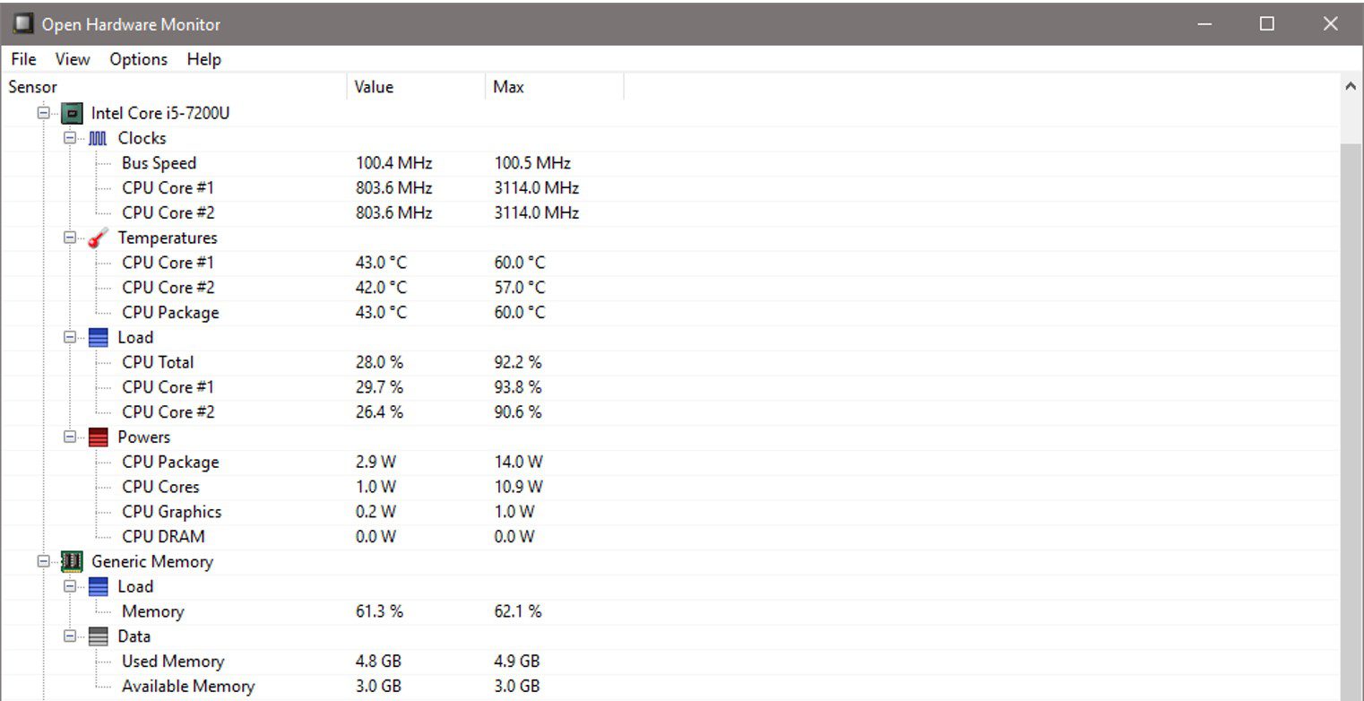
In order to send the CPU load to your Arduino, we first need to be able to access it. One of the easiest ways to do this is using a freeware application called Open Hardware Monitor.
The Open Hardware Monitor app runs in the background on your PC and minimises to the system tray. It collects information on a number of different hardware items on your computer and makes it available to be read using a Python script.
You’ll need to make a note of your processor name displayed in the monitor as you’ll need to update this in the python script in order to access your CPU load.
You’ll also need to set the Open Hardware Monitor to run on startup so that you don’t need to open it every time you restart your PC. To do this, go to options and make sure that “Start Minimized”, “Minimize To Tray” and “Run on Windows Startup” are all checked. Then minimise the app.
Posting The Data To Your Arduino Using A Python Script
Lastly, we have a python script which transmits the CPU load through the serial com port to your Arduino. The script reads the data posted by the Hardware monitor app, finds the CPU load and then posts the value to the Arduino.
I didn’t write this code. I’ve modified the code from Leonidas Tsekouras’s Arduino PC Monitor example in which he sends a range of data to be displayed on an external LCD display.
Here is the code:
#!/usr/bin/env python
# -*- coding: utf-8 -*-

import json
import os
import time
from urllib.error import URLError, HTTPError
from urllib.request import Request, urlopen

import serial
import serial.tools.list_ports

serial_debug = False

def space_pad(number, length):
    """
    Return a number as a string, padded with spaces to make it the given length
    :param number: the number to pad with spaces (can be int or float)
    :param length: the specified length
    :returns: the number padded with spaces as a string
    """

    number_length = len(str(number))
    spaces_to_add = length - number_length
    return (' ' * spaces_to_add) + str(number)

def get_json_contents(json_url):
    """
    Return the contents of a (remote) JSON file
    :param json_url: the url (as a string) of the remote JSON file
    :returns: the data of the JSON file
    """

    data = None

    req = Request(json_url)
    try:
        response = urlopen(req).read()
    except HTTPError as e:
        print('HTTPError ' + str(e.code))
    except URLError as e:
        print('URLError ' + str(e.reason))
    else:
        try:
            data = json.loads(response.decode('utf-8'))
        except ValueError:
            print('Invalid JSON contents')

    return data


def find_in_data(ohw_data, name):
    """
    Search in the OpenHardwareMonitor data for a specific node, recursively
    :param ohw_data:    OpenHardwareMonitor data object
    :param name:        Name of node to search for
    :returns:           The found node, or -1 if no node was found
    """
    if ohw_data == -1:
        raise Exception('Couldn\'t find value ' + name + '!')
    if ohw_data['Text'] == name:
        # The node we are looking for is this one
        return ohw_data
    elif len(ohw_data['Children']) > 0:
        # Look at the node's children
        for child in ohw_data['Children']:
            if child['Text'] == name:
                # This child is the one we're looking for
                return child
            else:
                # Look at this children's children
                result = find_in_data(child, name)
                if result != -1:
                    # Node with specified name was found
                    return result
    # When this point is reached, nothing was found in any children
    return -1

def get_hardware_info():
    """
    Get hardware info from OpenHardwareMonitor's web server and format it
    """
    global serial_debug

    # Init arrays
    my_info = {}

    # Get data
    if serial_debug:
        # Read data from response.json file (for debugging)
        data_json = get_local_json_contents('response.json')
    else:
        # Get actual OHW data (Modify to your Open Hardware Monitor's IP Address)
        ohw_json_url = 'http://192.168.20.10:8085/data.json'
        data_json = get_json_contents(ohw_json_url)

    # Get info for CPU (Modify to your CPU name shown in Open Hardware Monitor)
    cpu_data = find_in_data(data_json, 'Intel Core i5-7200U')
    cpu_load = find_in_data(cpu_data, 'CPU Total')

    # Get CPU total load, and remove ".0 %" from the end
    cpu_load_value = cpu_load['Value'][:-4]

    my_info['cpu_load'] = cpu_load_value

    return my_info


def main():
    global serial_debug

    # Connect to the specified serial port (Modify to your Arduino's COM port)
    serial_port = 'COM3'
    if serial_port == 'TEST':
        serial_debug = True
    else:
        ser = serial.Serial(serial_port)

    while True:
        # Get current info
        my_info = get_hardware_info()

        # Prepare CPU string
        cpu = space_pad(int(my_info['cpu_load']), 3) + '%'

        # Send the strings via serial to the Arduino
        if serial_debug:
            print(arduino_str)
        else:
            ser.write(cpu.encode())

        # Wait until refreshing Arduino again
        time.sleep(2.5)


if __name__ == '__main__':
    main()
You’ll need to update the IP address that your Open Hardware Monitor is posting the data too. This can be found in the Open Hardware Monitor app by going to Options -> Remote Web Server -> Port.
You’ll also need to change your processor name and check that the Arduino’s com port is correct.
Both the python script and then hardware monitor can be set to automatically startup with your computer and run in the background, so you don’t have to keep running them every time you turn your computer off. The python script can be automatically started using the windows “Start a Program” utility.
Using The Arc Reactor CPU Monitor
Upload the code your Arduino and make sure that the Open Hardware Monitor app is running on your computer and then run the Python script to start posting the data to your Arduino. You should then start seeing updates to your CPU performance on the OLED display and the reactor pulsing accordingly.
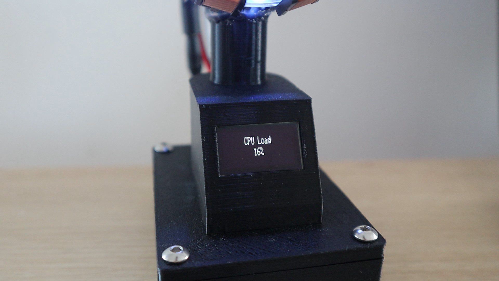
On start-up, with no data being transmitted, the OLED display should still display CPU Load 0% and the reactor should be pulsing slowly.
If you open up a benchmarking application to increase the CPU load to 100%, you will see it pulse really quickly.
You can make your own adjustments to the pulse durations and brightness levels in the code. I found it too distracting to have the pulse turn off completely each cycle, so I limited the minimum brightness and also set the low CPU usage pulse duration to be quite long. You can edit these by making changes to the mapped delay, to the brightness variable and to the fadeAmount variable.
Let me know if you’re going to be building your own arc reactor CPU performance monitor or what you’ve done with an arc reactor you’ve built.
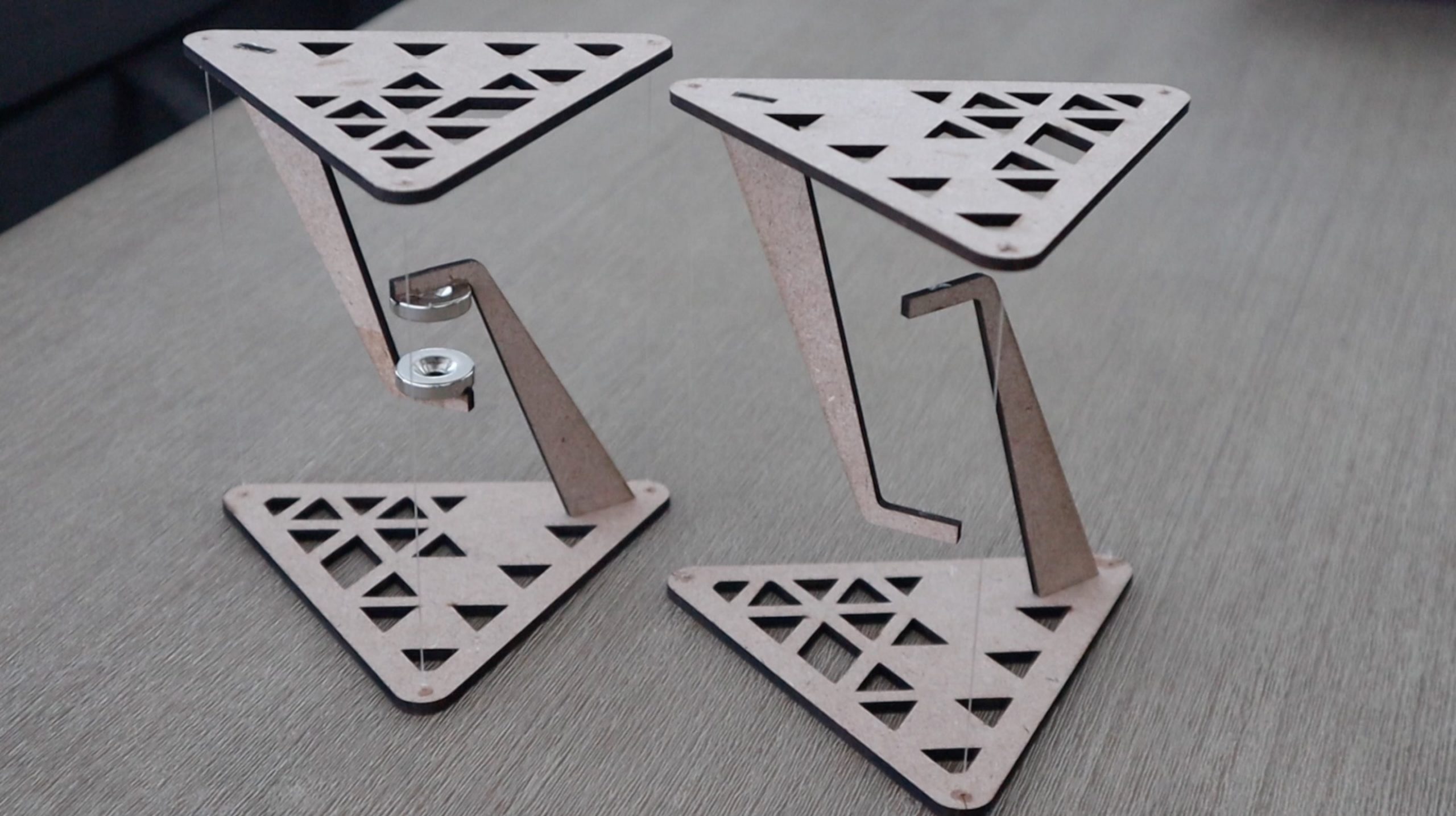
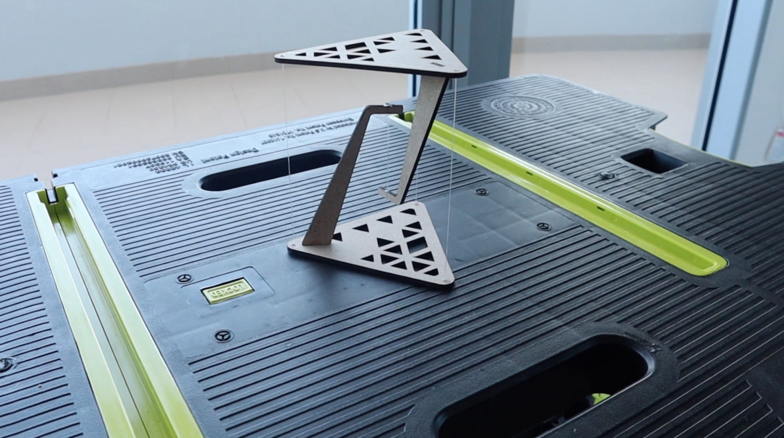
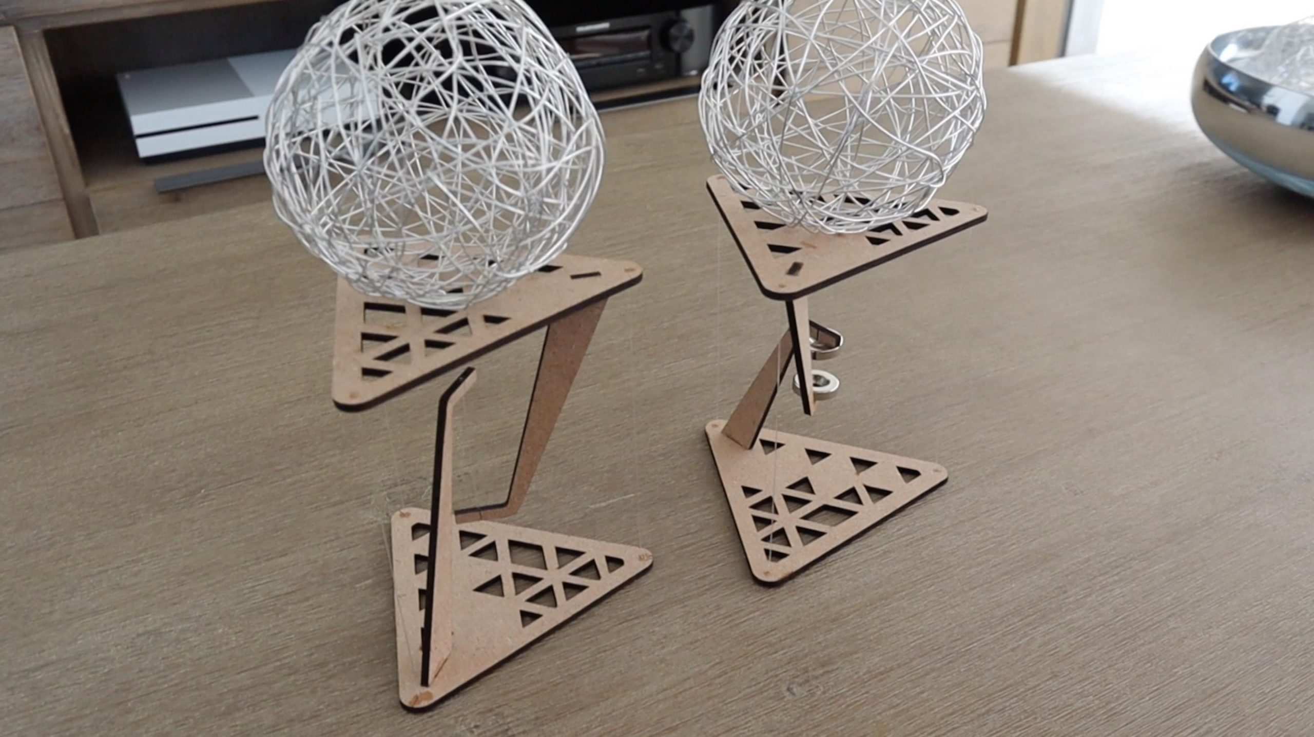
These tables look like they’re just floating in the air, but they’re actually a clever demonstration of the principle of tensegrity. The principle of tensegrity originated in the nineteen fifties and is still used in the design of modern buildings and structures. The worlds largest tensegrity structure is currently the Kurilpa Bridge in Brisbane, Australia. In this guide, I’ll be showing you how to build your own tensegrity tables step by step.
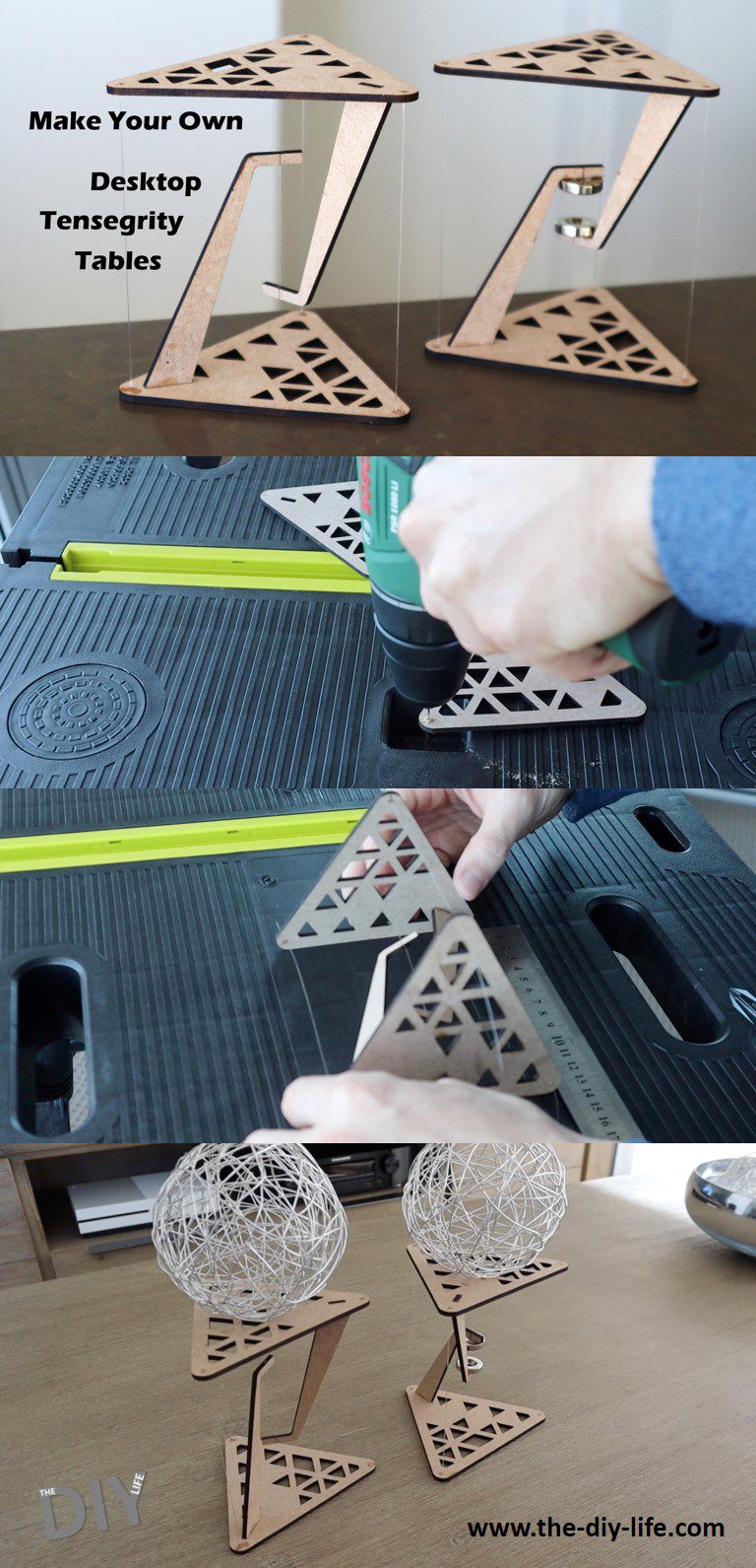
Have a look at my video summary of the build and the final product, otherwise, read on for the step by step instructions.
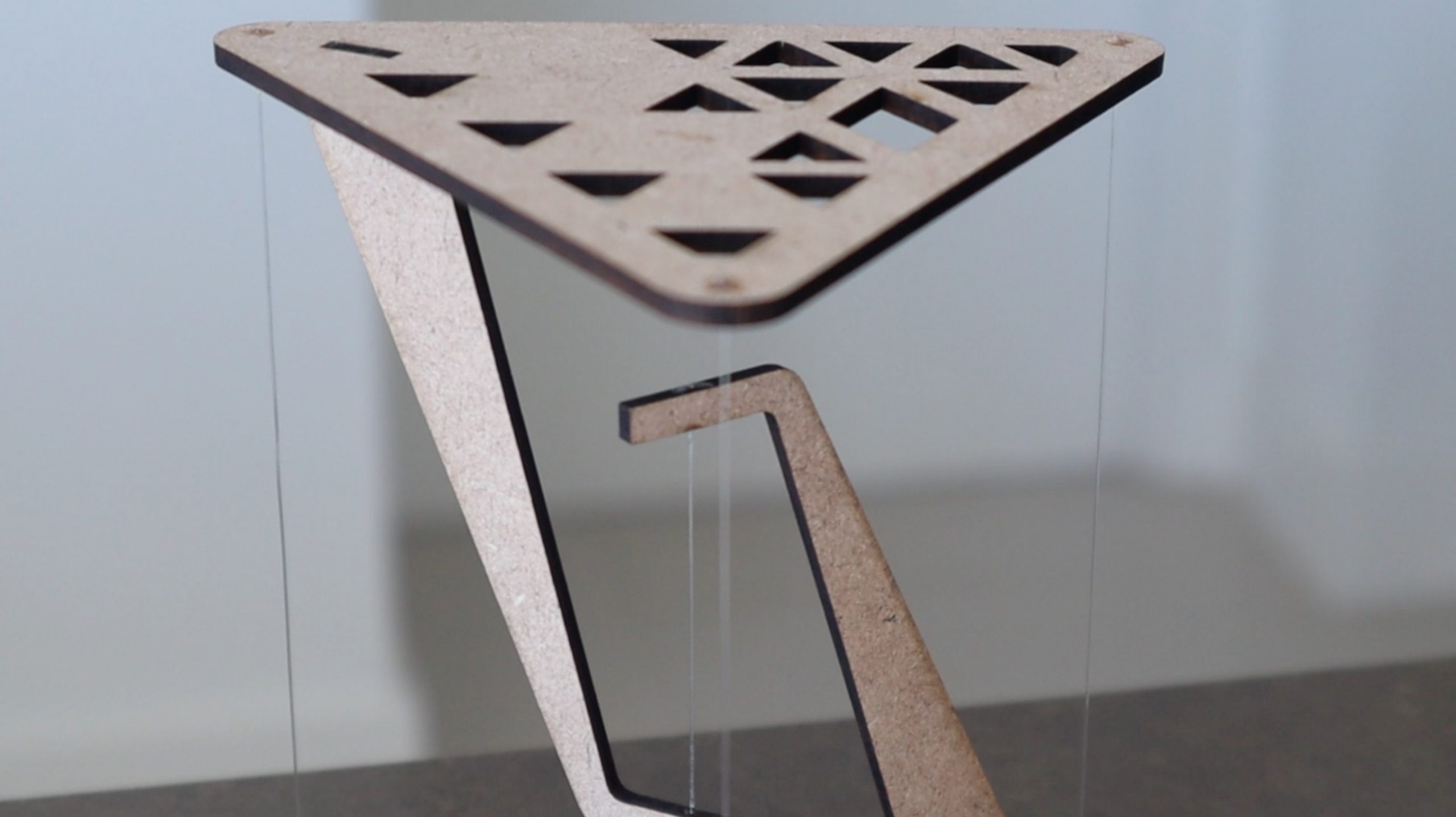
At first glance, it appears that the top surface is being supported by the three outside pieces of fishing line, which doesn’t make sense since we know that fishing line or string can’t support compressive loads. But taking a closer look, you will see that the line doing all of the work is actually the one in the centre.
The piece of fishing line in the centre of the structure is in tension and is supporting the load of the surface of the table and whatever is placed onto it. The three pieces of line on the outside are simply holding the top surface in place so that it remains directly overhead the centre line and doesn’t fall over.
If any of these four lines are cut, the table will collapse under its own weight.
To better understand tensegrity tables and how they work, let’s try building our own ones.
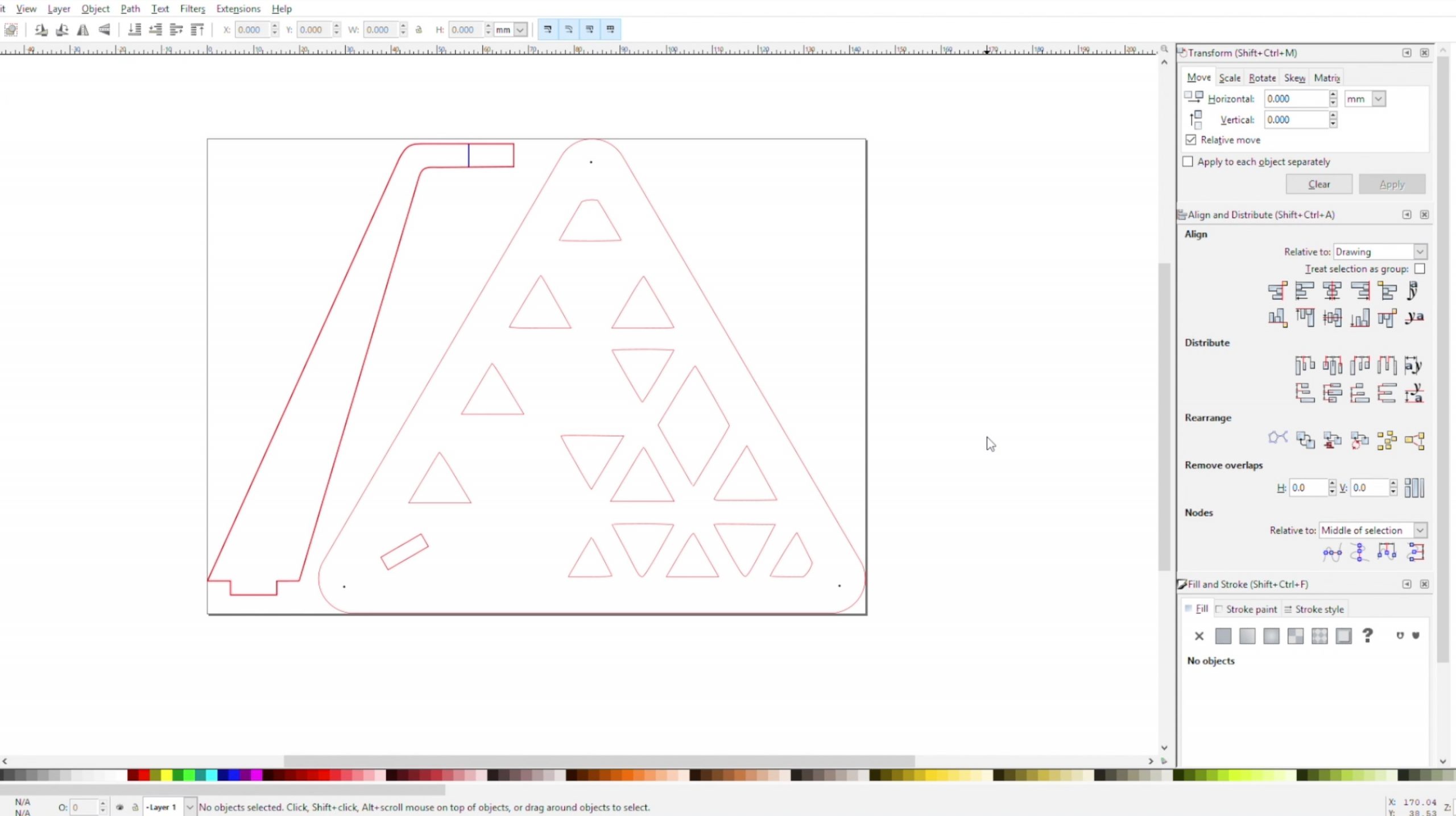
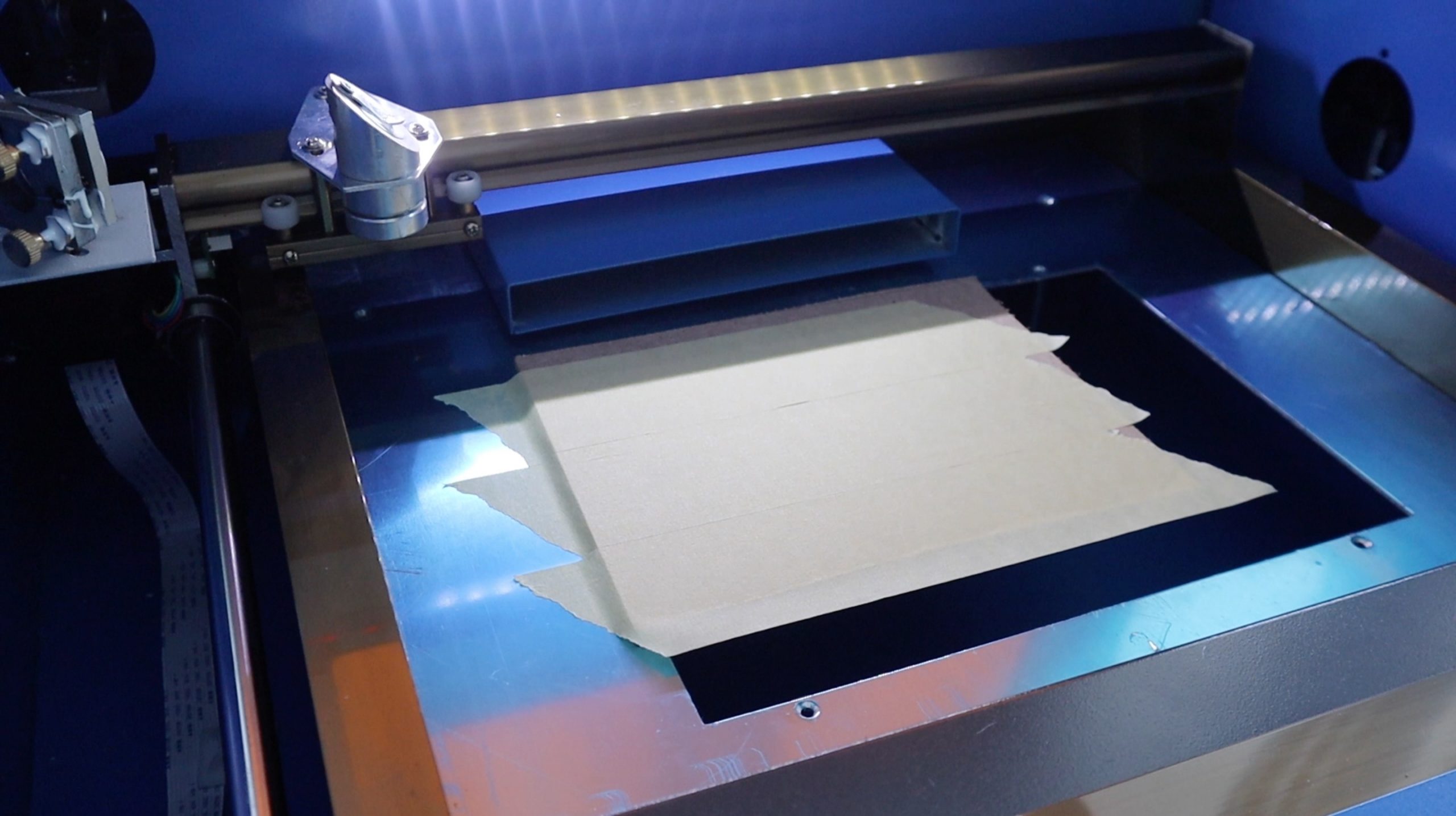
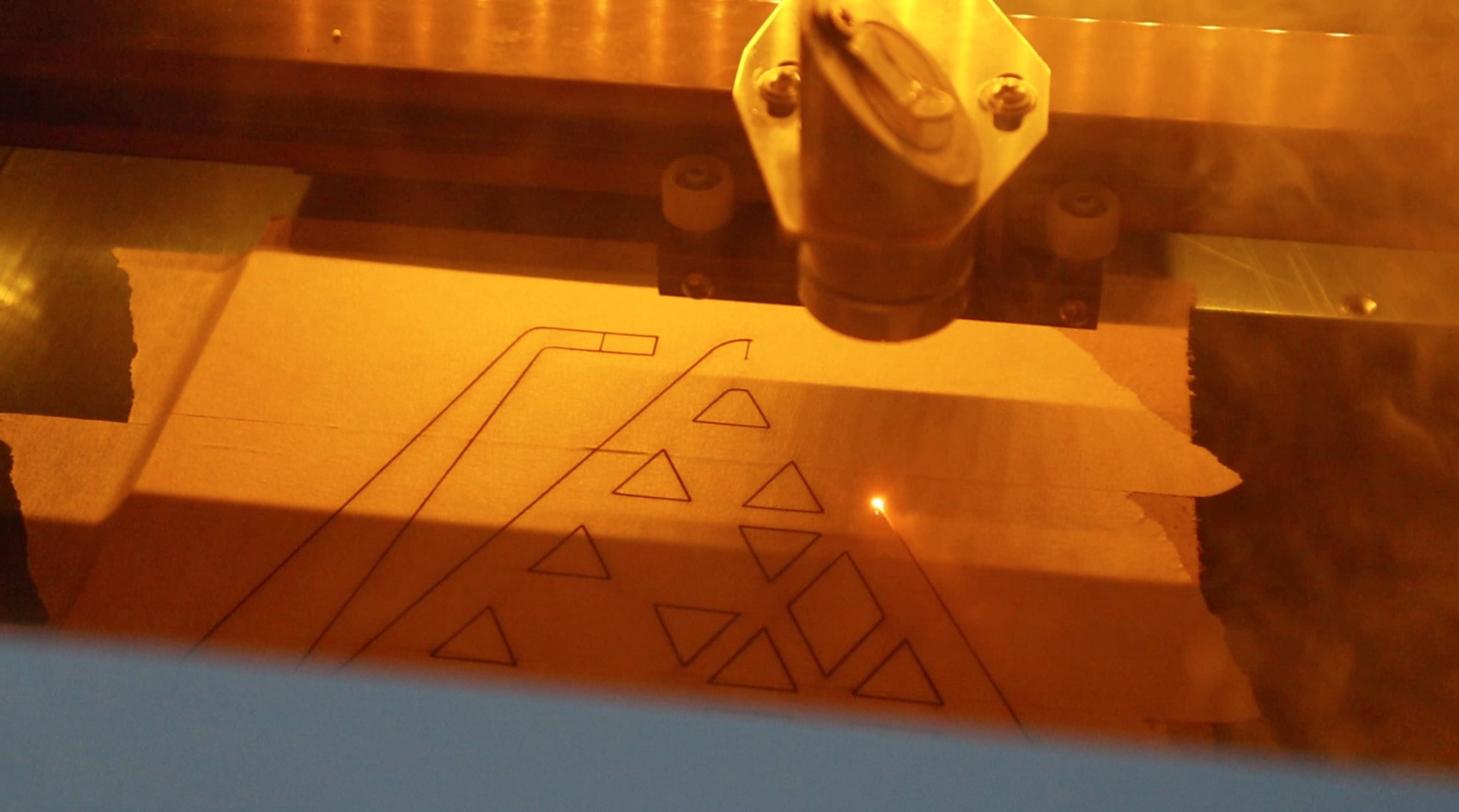
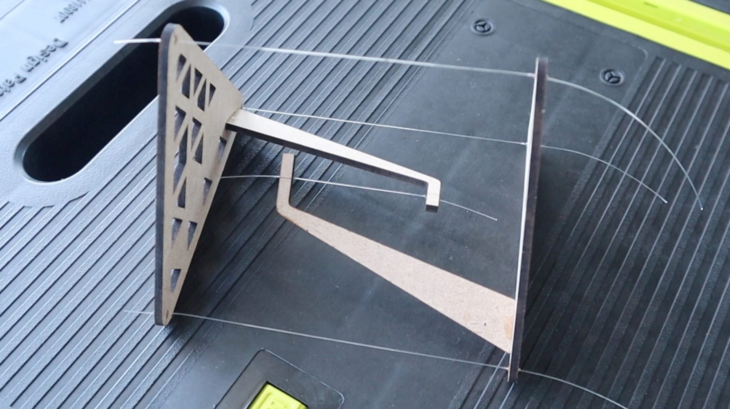
These tables were cut on a laser cutter, but you can still cut out the outlines of the components and build your own using MDF, acrylic or plywood if you don’t have access to a laser cutter, or make use of an online laser cutting service.
I designed the basic components in Inkscape, to be laser cut from 3mm MDF. You could also cut them from plywood or acrylic and you can cut the outlines out by hand if you don’t have access to a laser cutter.
The file above includes the Inkscape svg files as well as dxf files and an A4 printable pdf template, so you should be able to find an application to open and print or cut them out.
I’ve added a few engraving marks as guides for the holes to be drilled for the fishing line as well.
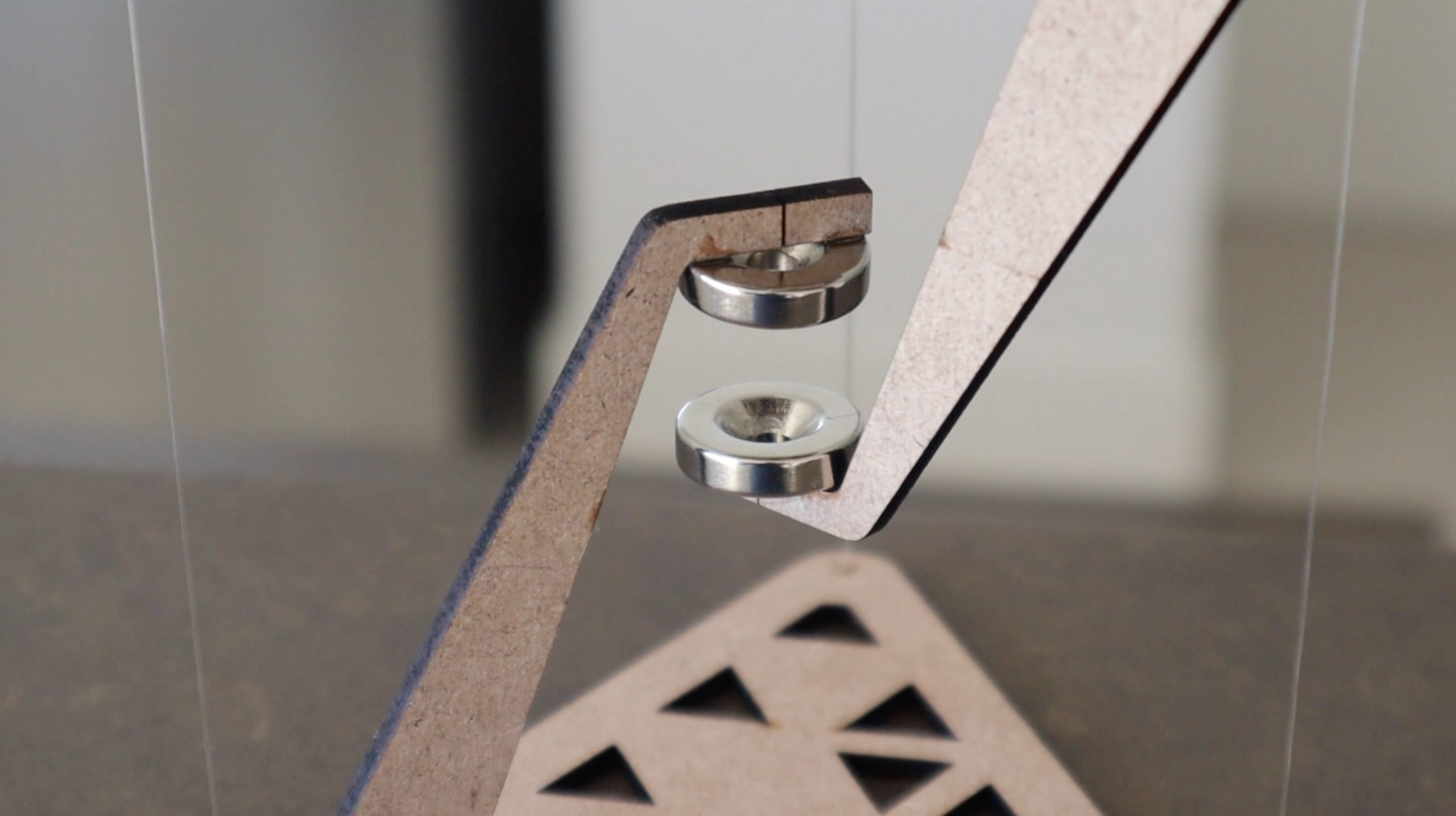
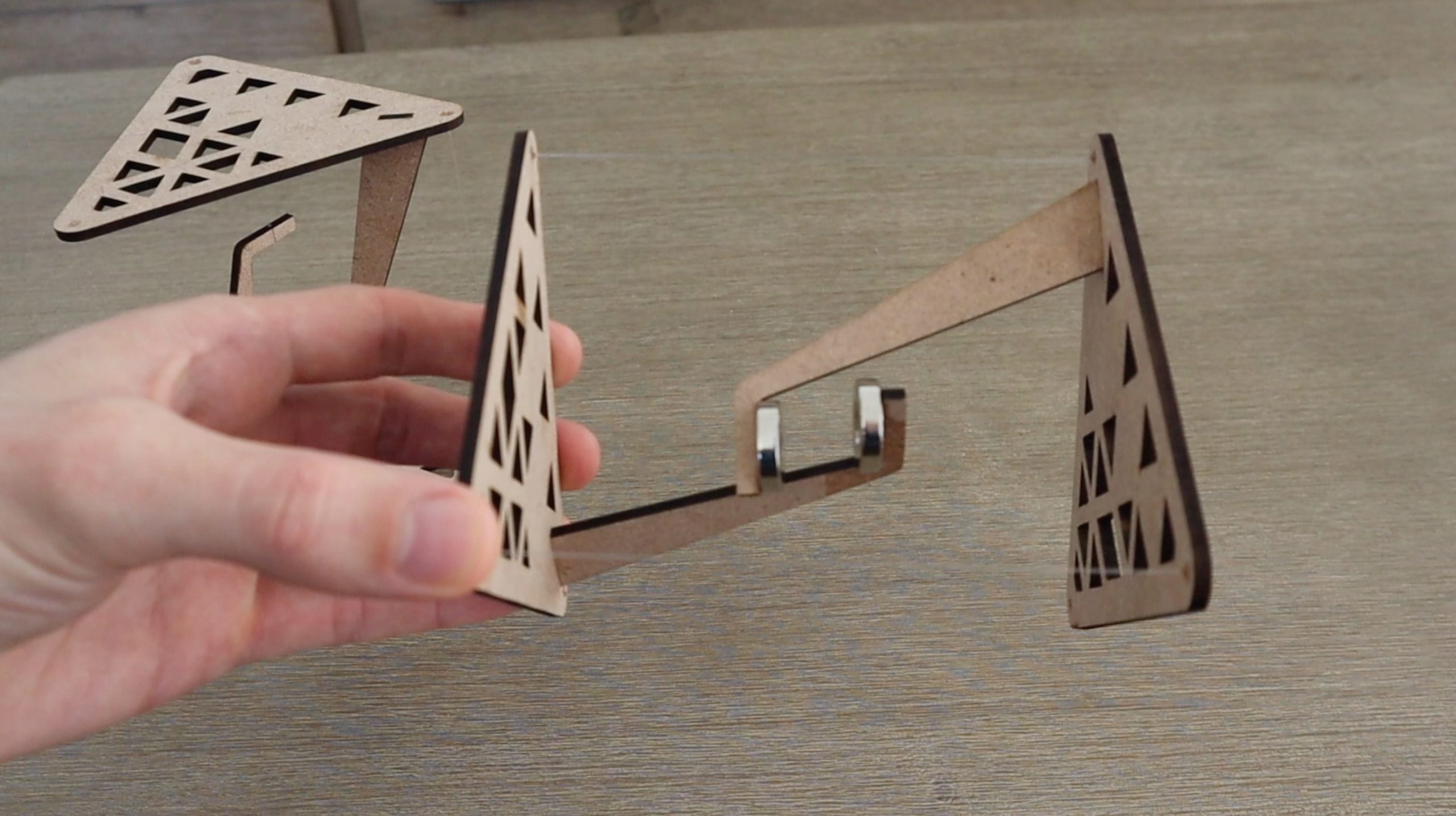
I designed two versions of these tables, one which is supported by a strand of fishing line in the centre and one which is supported by two agents. The flat sections are the same, I’ve just adjusted the height of the vertical section to accommodate the magnets in the centre instead of the fishing line. The magnets add an interesting dynamic to the table, as there is now effectively no physical component holding the table up, it’s purely supported by the invisible magnetic force between the two magnets.
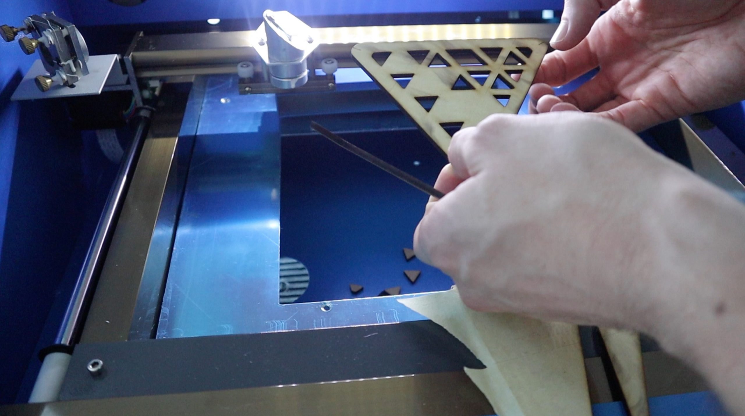
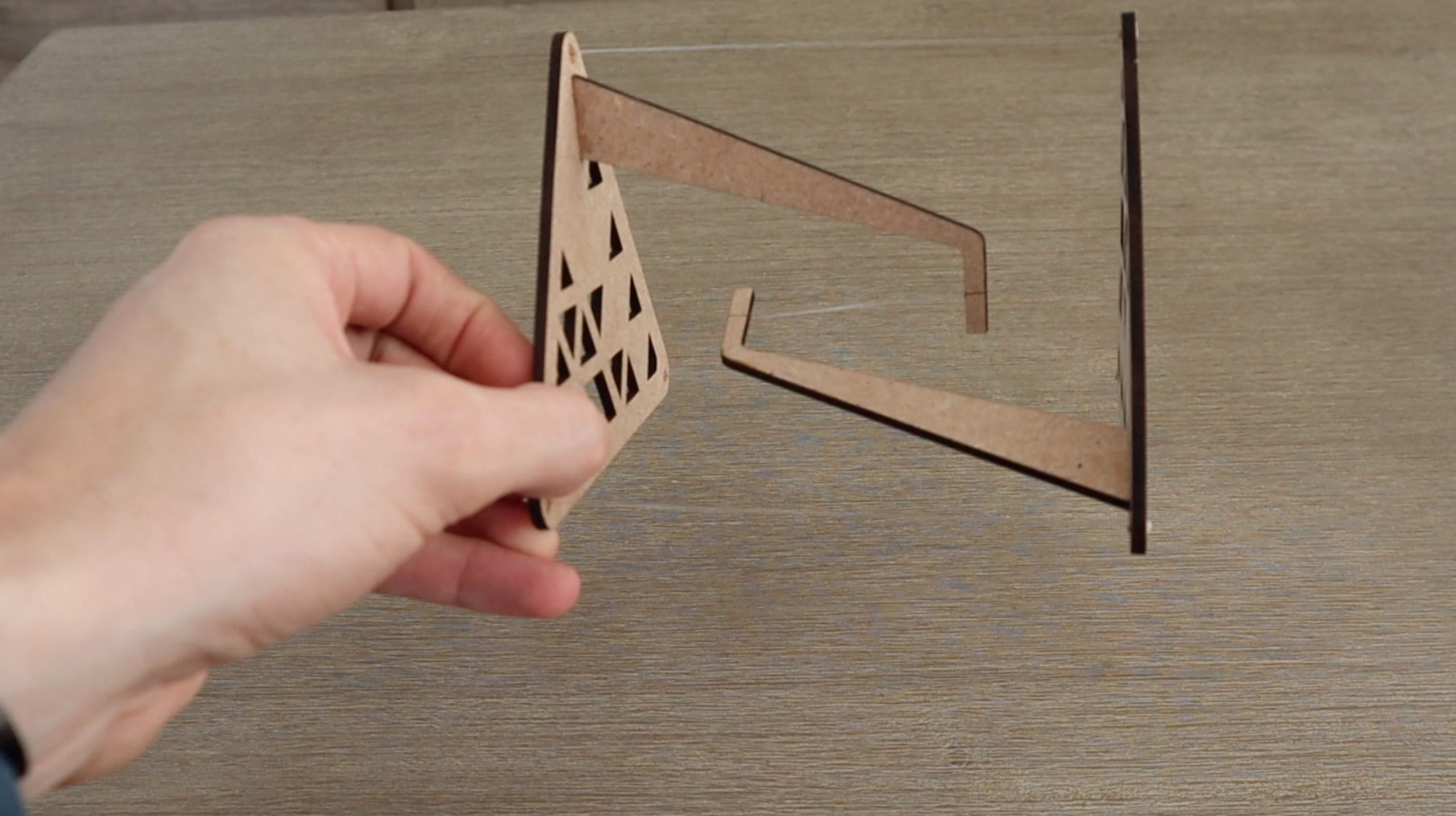
Cut your components from your chosen material. You’ll need two table ends and two vertical supports for each table.
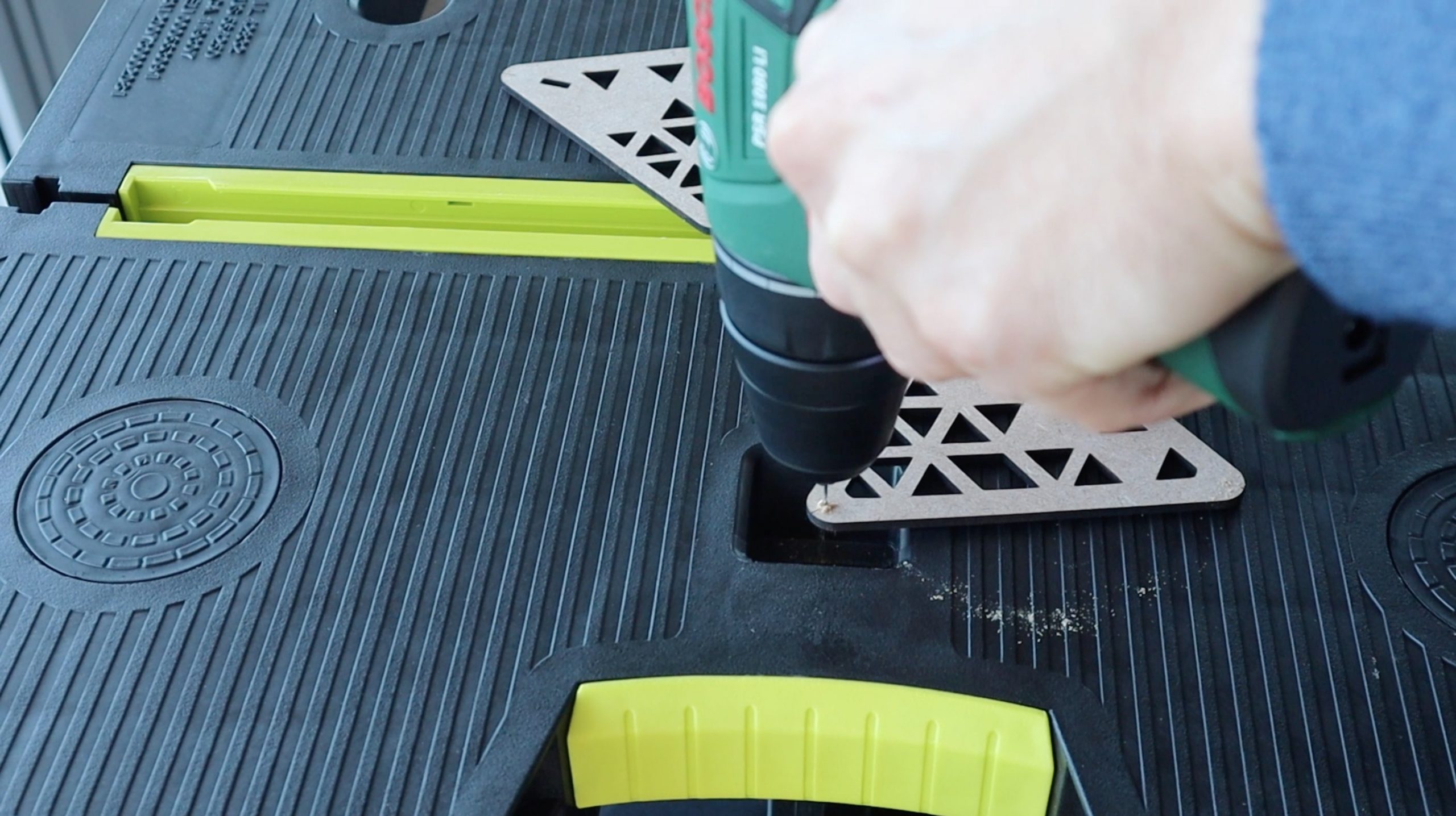
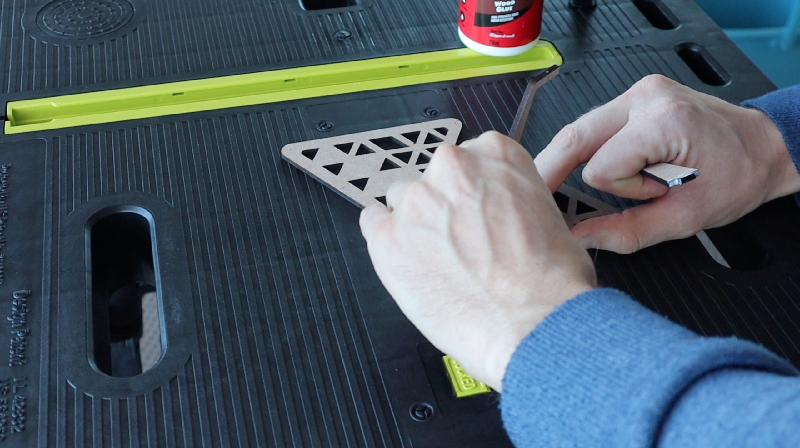
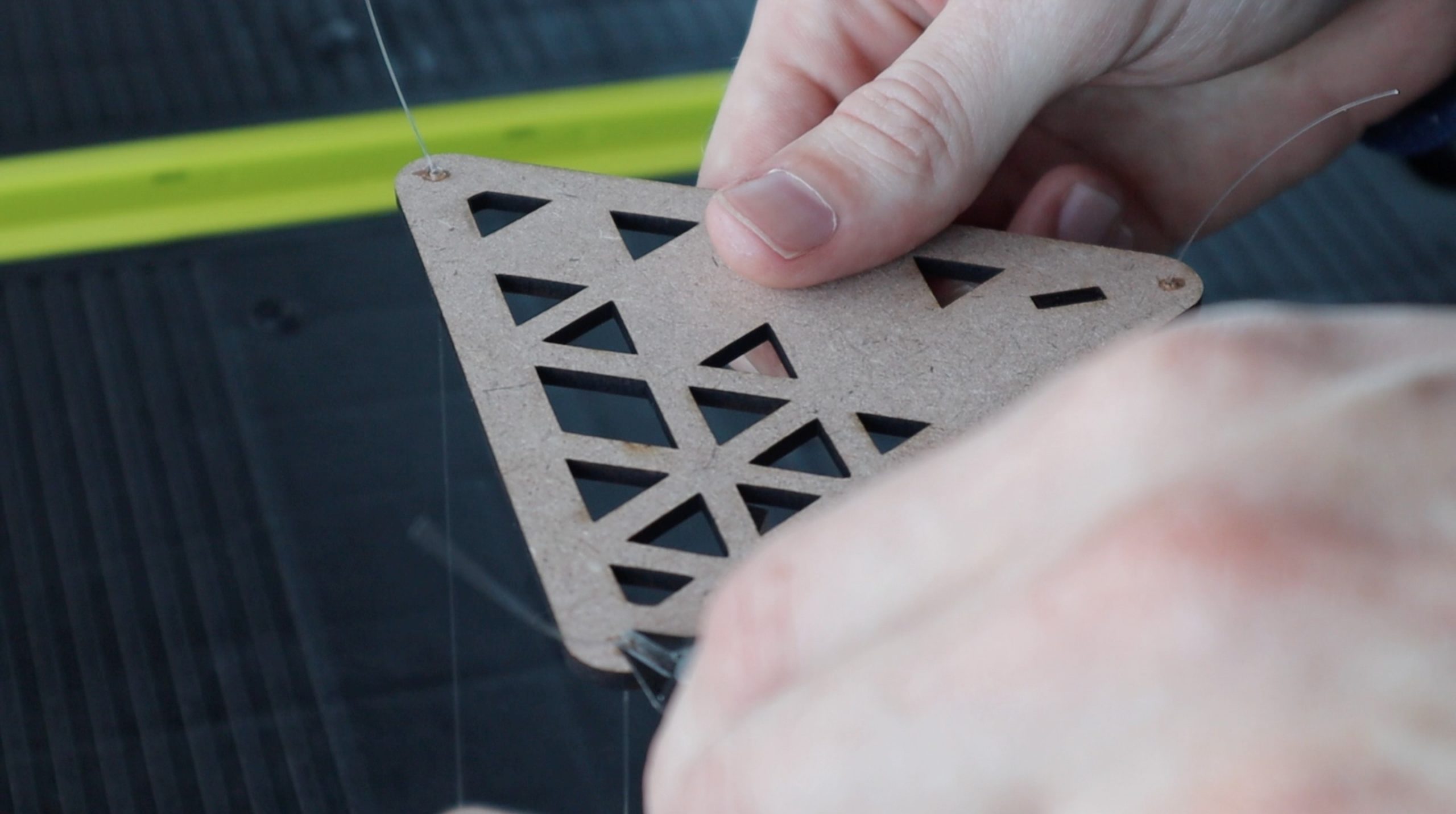
Once you’ve cut out your components, you need to drill the holes through them for the fishing line or thread. I drilled these using a 1mm drill bit on engraved markings. You can adjust the drill bit size to suit the diameter of your fishing line or thread.
You’ll then need to glue the vertical pieces in place using PVA wood glue and wait for the glue to dry. There is a slot designed into the table ends to position and align the vertical support.
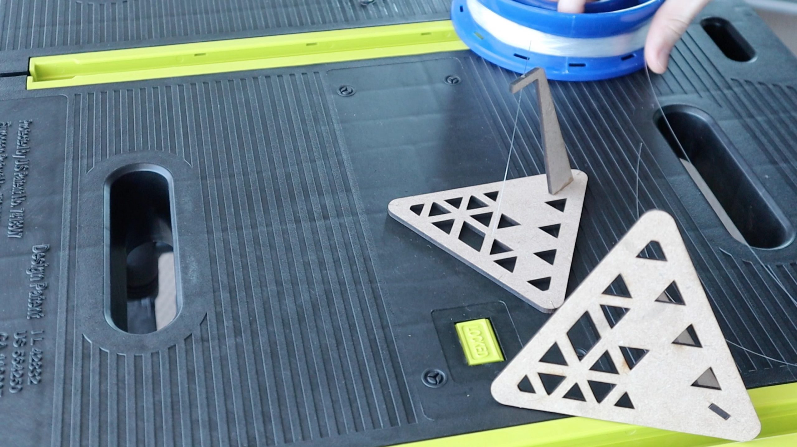
Once that’s done, you can add your fishing line or thread. Fishing line is a bit easier to use because it doesn’t fray and it’s more rigid, so its easier to thread through the holes. Cut four lengths a lot longer than you need, you can then trim them when you’re done. I found that lengths of around 200mm (8″) worked well.
Glue one end of each line into the bottom side of the table first. You can either tie a knot at the end of the lines or simply glue them into place with some super glue. I found it easier to position them accurately and glue them into place rather than trying to get the knot tied in the correct place. A single drop of super glue on each side was sufficient to hold the line in place and dried quite quickly.
Then glue the tension line in the middle into place, leaving around a 50-60mm (2″) gap between the two centre pieces. Glue or tie both ends of the tension line into place.
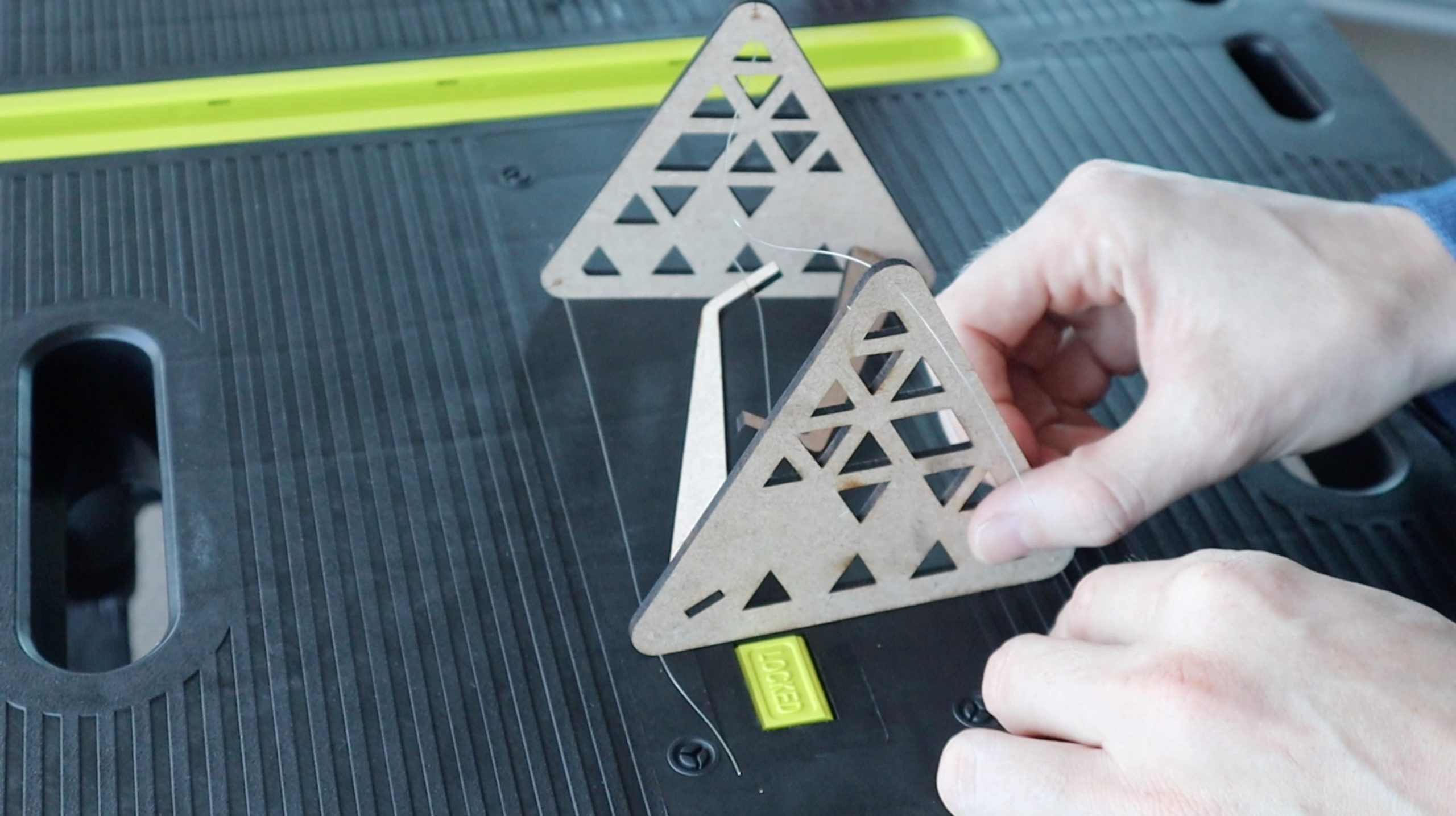
Then fed the three outer lines through their holes. The last step takes a bit of patience to get right. You need to glue or tie the three outer lines into place so that there is a little bit of tension on the centre line but also keep the top and bottom surfaces as close to parallel as possible. So all three lines need to be as close to the same length as possible. It helps to use a ruler to get this part right. Depending on the length of your centre strand, you’re looking for these lines to be around 130mm (5″) long. Also, use a small amount of glue to temporarily hold them in place until you’re sure that they’re correct so that you can undo a joint if you need to.
Once you’re happy with your table, trim off the excess fishing line and make sure that the glued joints are secure and dried.
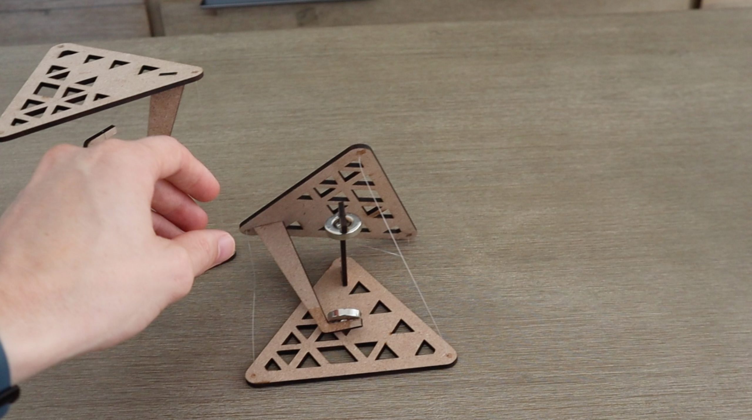
If you’re using magnets, glue the outside three lines into place at the correct and even length, around 130mm (5″) and then add the magnets to the middle afterwards, with opposite poles facing each other so that they’re attracted to each other.
The magnetic table looks cool, but can’t really hold much weight. You could get more by positioning the magnets closer together as the magnetic force of attraction between two magnets is proportional to the square of the distance between them. There is a bit of a tradeoff here though because if they’re too close together then you can see the gap between them well and then it just looks like the magnets are rigidly holding up the table.
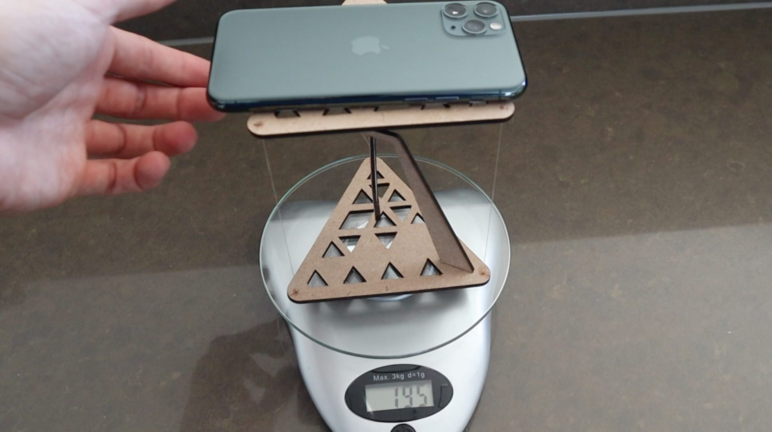
I tested the fishing line table to see if it could hold up my phone. It held up just under 200 grams but the outside lines did start flexing, so it probably couldn’t take too much more than this.
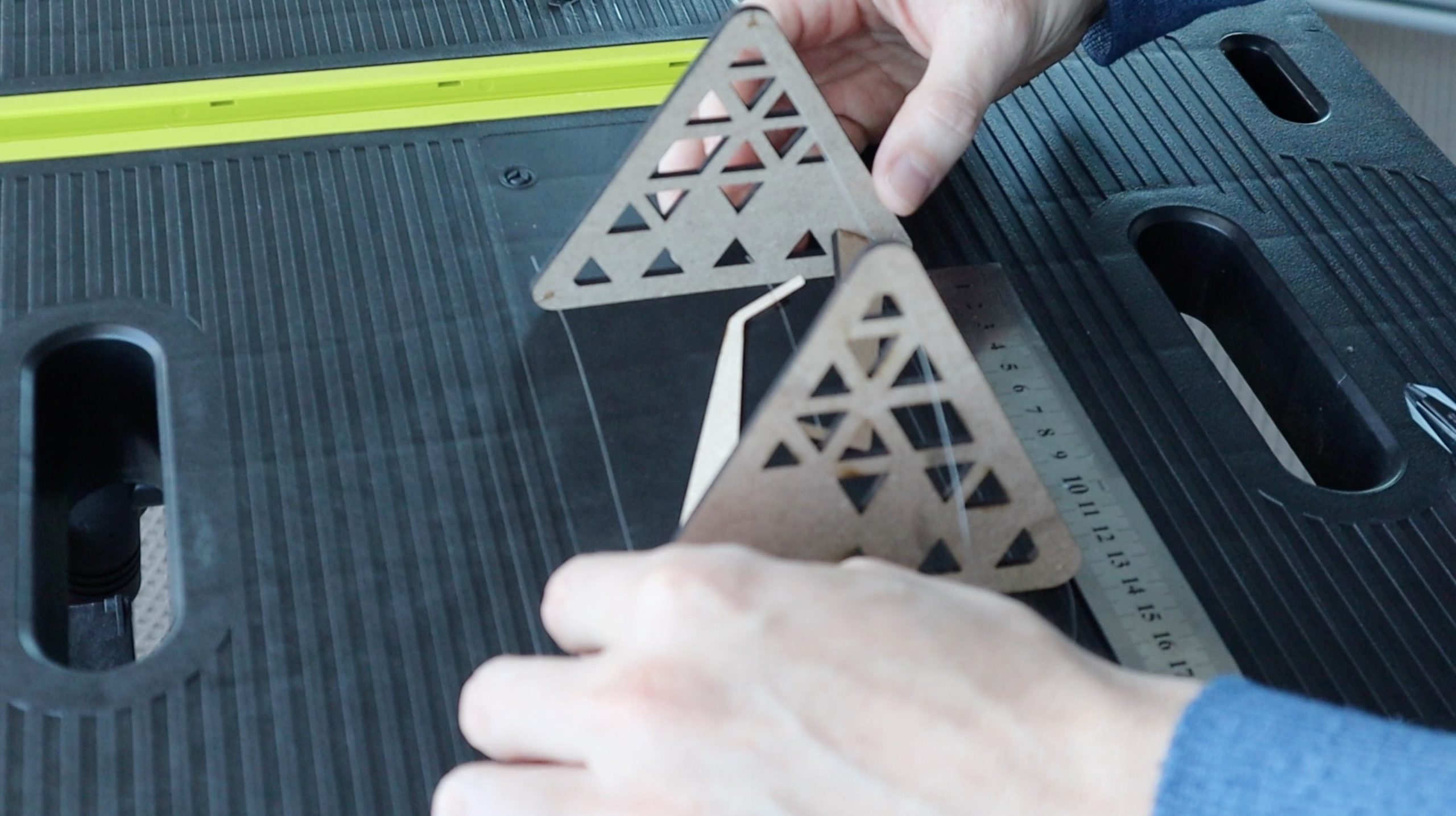
These tensegrity tables are surprisingly rigid, you can even pick them up and hold them sideways.
The magnetic one will also hold itself up sideways but it collapses if you put too much weight on it. You can just pull the magnets back up towards each other to reset the table.
Enjoy making your own tensegrity tables! Let me know how it goes for you and what your designs look like in the comments section below.
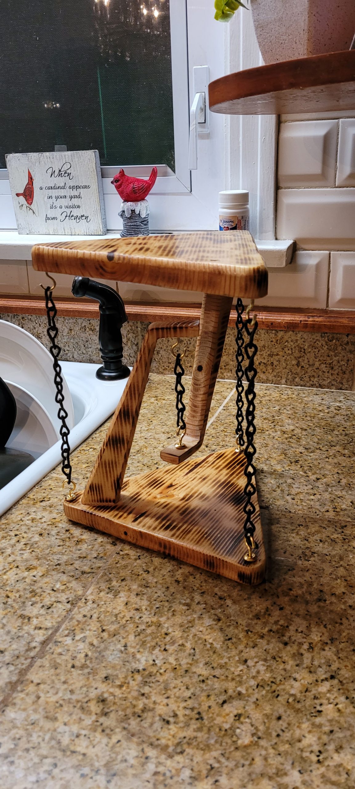
Community Builds
Michael Marletto built a larger version of the table from wood and suspended the surfaces using chains. It really came out well and can probably take quite a lot more load than the smaller MDF ones:
Water scarcity is a real issue throughout the world, so paying attention to your water usage and being mindful of ways you can save water can help future generations.
Saving water at your own home is easy to do. You install a toilet bladder, avoid watering your flowers and yard in the midday sun, and harvest rainwater and you’ve already made a great dent in your usage.
Saving water when you’re away from home can be a little trickier, though. You’re not going to carry around a toilet bladder to use at a restaurant or friend’s house. These tips will help you feel good about your water-saving efforts, no matter where you are.
Use a Refillable Water Bottle
Conserving water can be as simple as considering which container you’ll drink it out of. To use pick the best container, buy a refillable water bottle or flask that you can carry with you in your car, bike, or while walking.
Disposable water bottles take water to produce. So do refillable bottles, but you’ll be reusing those hundreds or thousands of times compared to a single-use. It’s smarter and better for the environment if you stop using disposable water bottles entirely.
Reuse Towels at a Hotel
Chances are, you reuse your bath towels multiple times before washing them at home. Our to-do lists are long enough without having to wash and fold extra laundry unnecessarily. Who wants to do that?
But at hotels, many of us feel more indulgent. We don’t treat our hotel rooms like we’d treat our house, and we leave those soggy towels on the bathroom floor, secure in the knowledge new ones will be brought to our rooms the next morning.
But with laundry making up as much as 16 percent of the water usage at a hotel, those reused towels can add up quickly in terms of saved water and reduced bills. It just takes a second to hang up your towels, and there’s no reason you can’t use them for the full week of your vacation.
Depending upon the length of your vacation and how many towels are in your room, you could save one load of laundry during your trip just from reusing towels. That can save at least 14 gallons of water or more if the hotel doesn’t use an energy-efficient appliance.
Eat Locally When on Vacation
When you’re travelling, look for roadside fruit stands and restaurants that advertise using locally-grown foods. Transportation of food from one country to another or one state to another can add a lot to the water footprint of the food you eat. It takes resources and energy to get that food moved.
The fruit you buy at stands hasn’t been washed as much as packaged foods in your grocery store has, and it generally isn’t packaged in plastic that takes water to produce. If you don’t see any packaging on your food, you’re saving water usage just from that.
Pick Foods Low on the Food Chain
Foods higher on the food chain take more water to produce. The bigger the animal you’re about to consume, the more water it took to get that food on your plate.
Beef takes about 1,847 gallons for every pound of meat, compared to pork at 718 gallons per pound. Chicken takes less water to produce than either of those meats.
Even better, opt for a few meatless meals every week while eating out in restaurants or on the road.
It takes 1,056 gallons of water to make one gallon of brewed coffee.
A gallon of beer requires 296 gallons of water to produce.
A gallon of wine takes 872 gallons of water to make.
If you’re tired of water, reach for tea. It only takes 108 gallons of water to produce one gallon of tea.
Carpool or Ride Your Bike
Producing gasoline takes water, so the less fuel you burn on driving, the less water you’ll be using. To conserve water, see if you can start an office carpool. It will save you and your coworkers money while also cutting down on water usage.
A better bet if you can do it is riding your bike or walking to wherever you’re going.
It All Adds Up
Sometimes the steps we take to save water can seem so small in the grand scheme of things. But every little bit truly does add up. And if enough people make a few changes to conserve water when they’re away from home, it will make a big difference in the long run.
What are some of the ways you save water outside of your home? Let us know in the comments section below.
Once mould starts growing on caulk or silicone joints and corners in your bathroom, it can be quite difficult to clean. You can scrub away for hours using bathroom cleaners and not really make much progress. We’ve found a solution that works well to remove mould on caulk and doesn’t require any scrubbing, you probably even have most of what you need in your home already.
You’ll need to mix the baking soda together with the bleach in your container. Start by adding a small amount of each and work until you run out of one of the ingredients. The mixture should form a paste which is quite thick and not drip off of the toothbrush, similar to toothpaste. The quantities are approximate and may need to be adjusted a little depending on how thick your bleach is.
Once you’ve got your thick bleach and baking soda paste, head into your bathroom and open up a window or turn on the extractor fan to get some fresh air flowing through the room. The mixture has a strong smell when you start spreading it out. You might also want to wear rubber gloves so that you don’t get it on your hands, undiluted bleach can be quite harsh on your skin and may cause burns or an allergic reaction.
Use the toothbrush to gently brush the mixture onto the mouldy spots, completely covering them. Make sure that the paste is thick enough to be held in place for an hour or so, it shouldn’t run down or drip off of the joint but should also completely cover the mould and shouldn’t be crumbly.
Note: You might want to test the mixture in a small hidden area to make sure that it doesn’t cause discolouration of your tiles.
Once you’ve brushed the mixture onto all of the mouldy spots, you just need to wait for the bleach to do the work. This usually takes about an hour, depending on how bad the mould is. It’s a good idea to check on the paste halfway through to make sure that it’s still in place.
After an hour, use some warm water and the toothbrush to wash the paste away. Make sure that it doesn’t drip onto your floor or bathmat or towels in the process as it may discolour them.
Once you’re done, the mould should be gone, or at least significantly lighter. Sometimes stubborn mould requires a second treatment.
Have you tried this method to clean the mould from your caulk or silicone joints and corners? Let us know what worked for you in the comments section below.
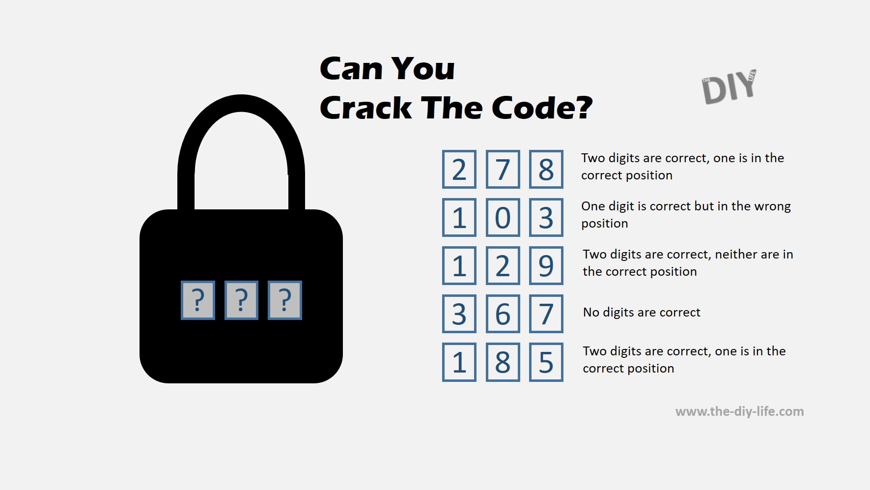
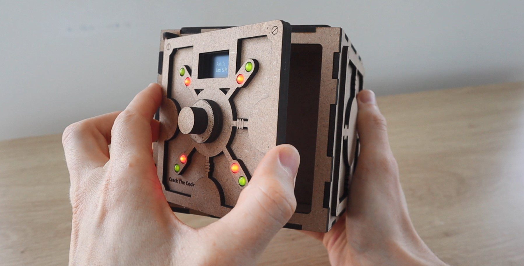
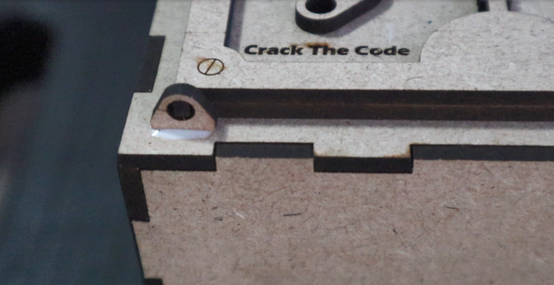
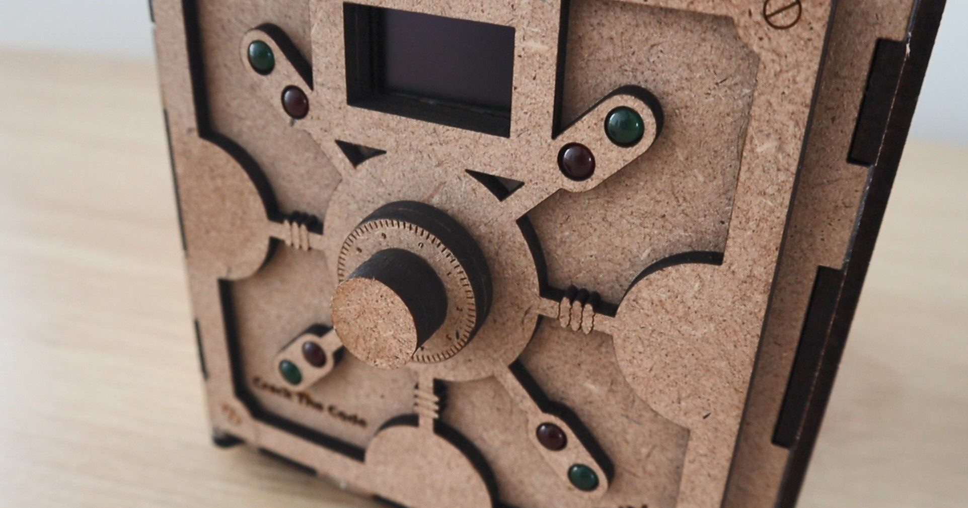
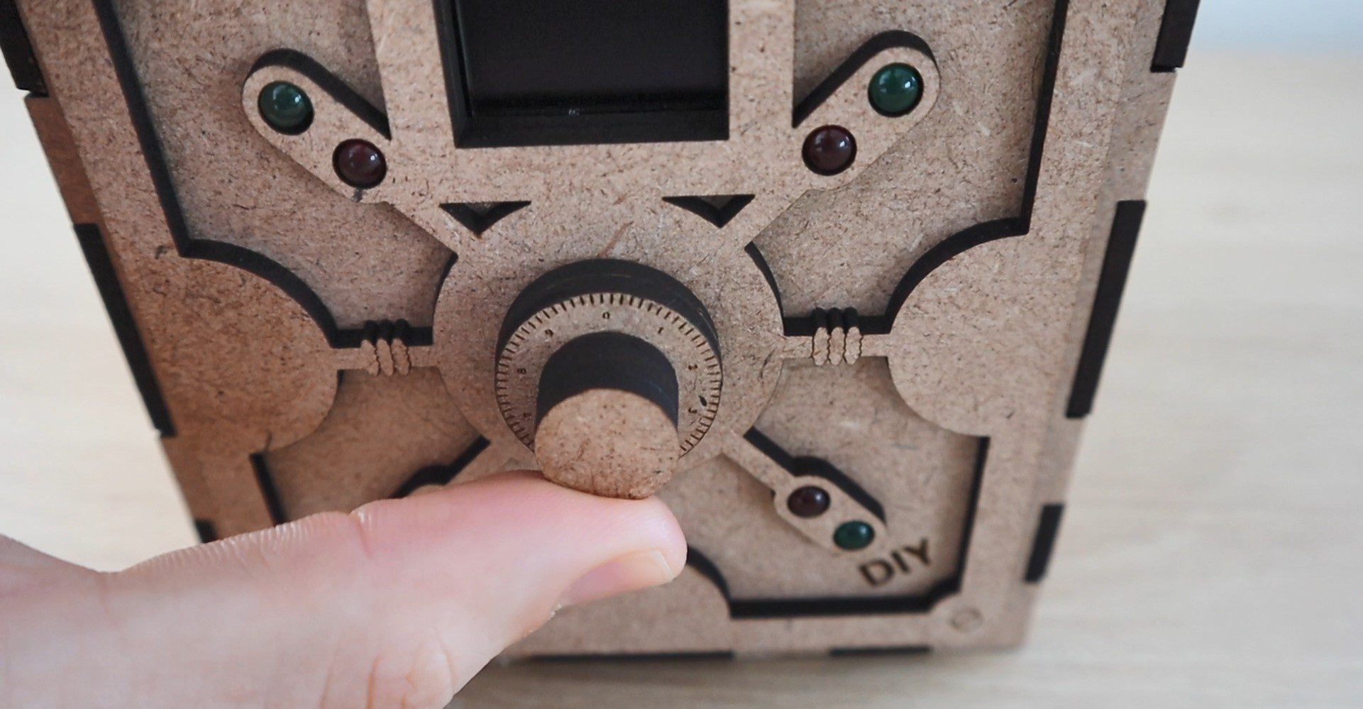
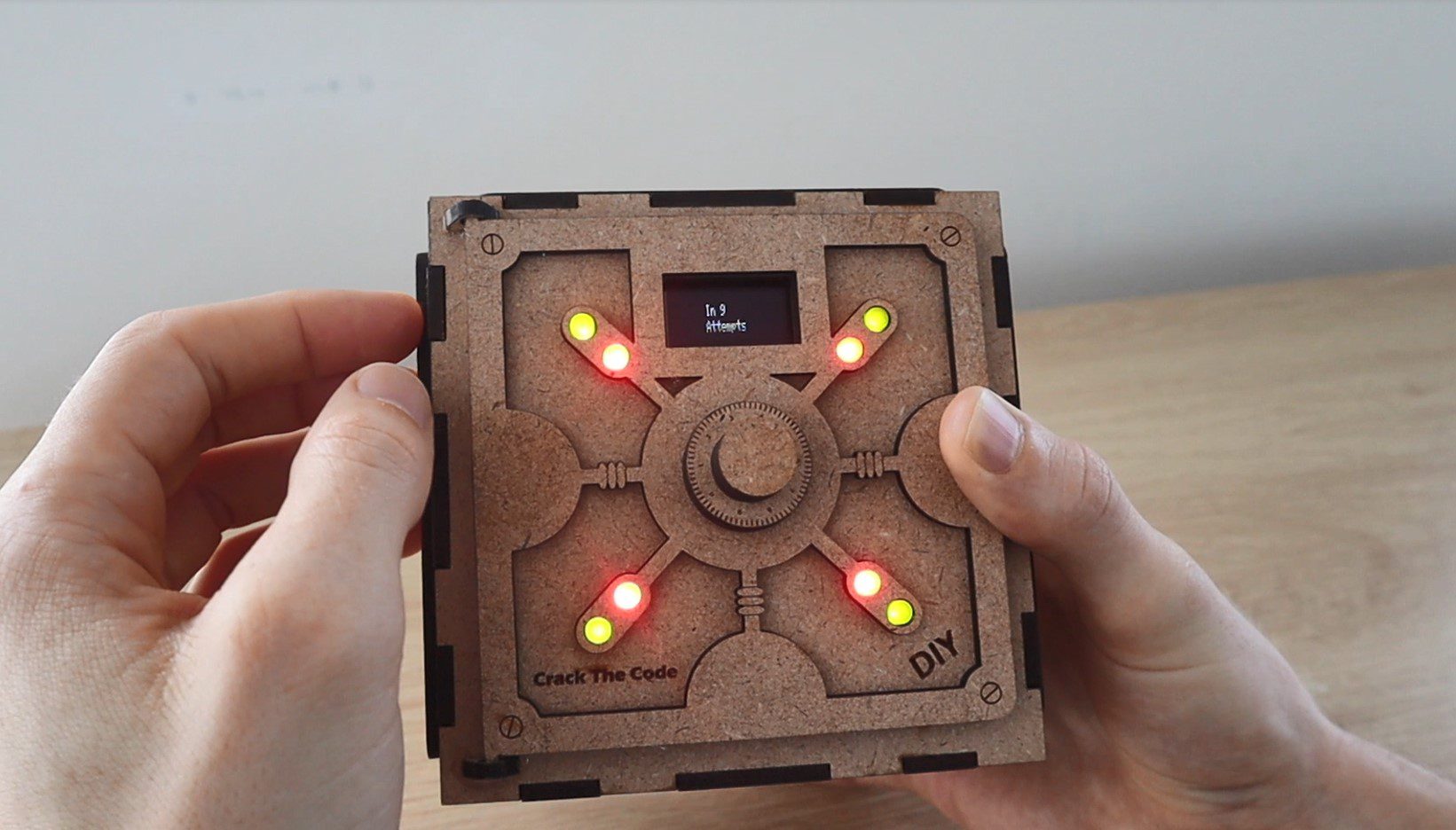
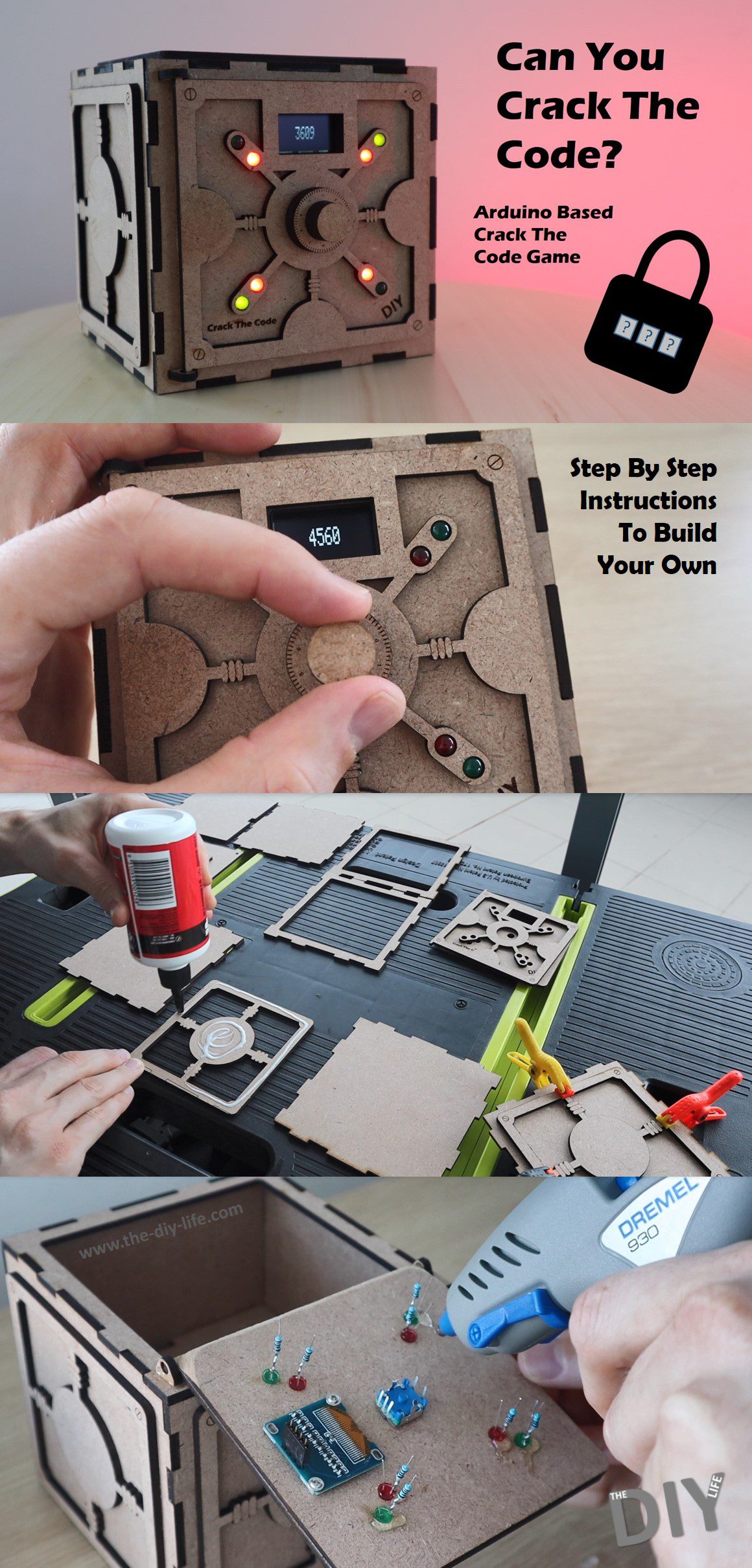
In this project, I’m going to be showing you how to build your own Arduino based crack the code game. You use a dial to guess the randomly generated code to the safe and 8 LEDs on the front of the safe then tell you how many of the digits you’ve guessed are correct and how many are in the right place as well. Using this feedback you can work your way towards cracking the code to the safe, and once you do, the game will then tell you how many attempts it took you to crack.
Here’s a video of the build. Read on for the full step by step instructions.
This project assumes you know the basics of Arduino programming, otherwise read our article on getting started with Arduino.
There have been a number of different forms of this game over the years, from physical pegboards in the 70s to video games, and more recently you may have seen these types of puzzles as single images on social media platforms.
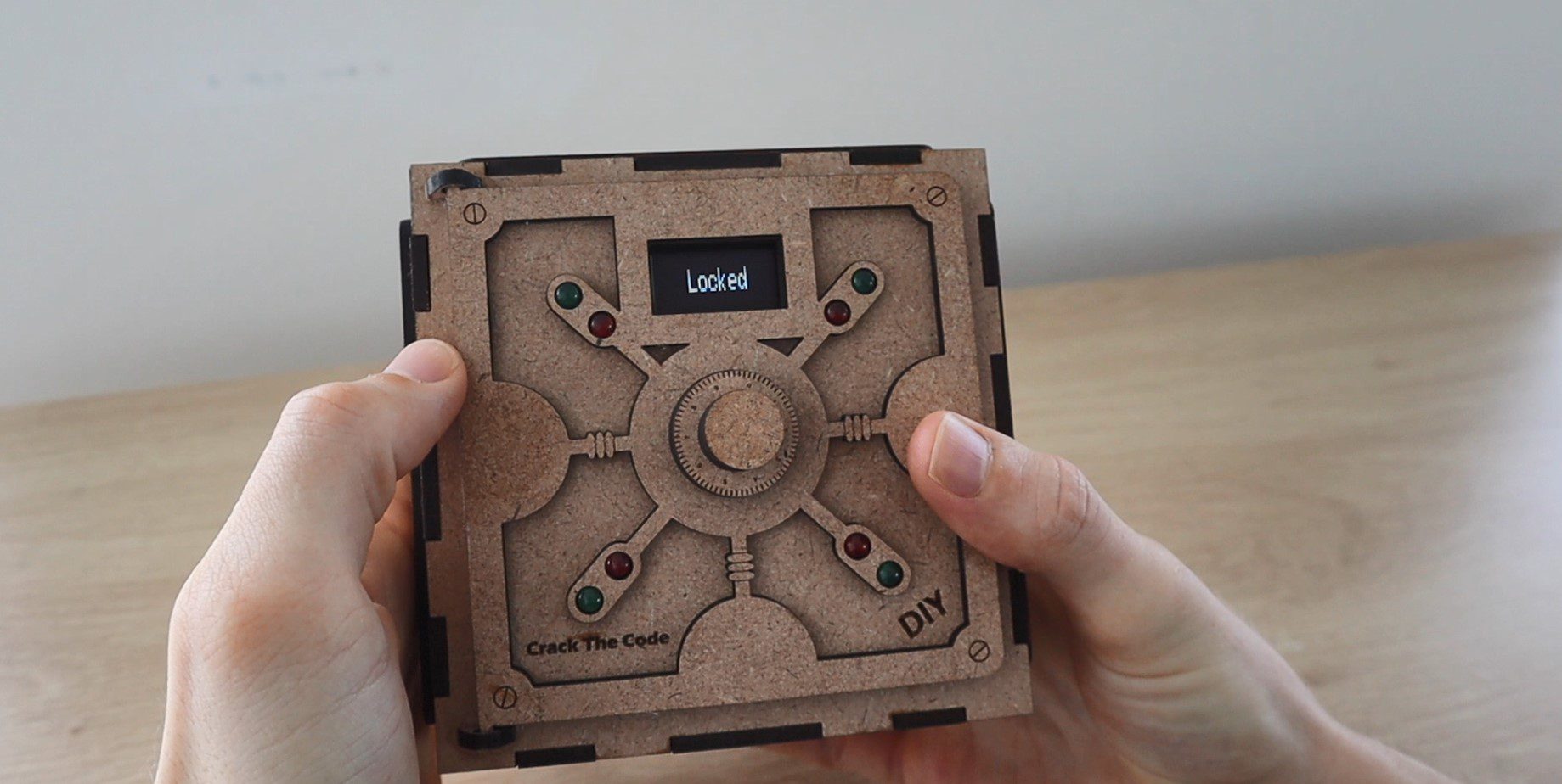
The safe is initially open, allowing you to put something into the inside compartment. You then push the dial to lock the safe using a servo on the inside of the door and a random code is generated.
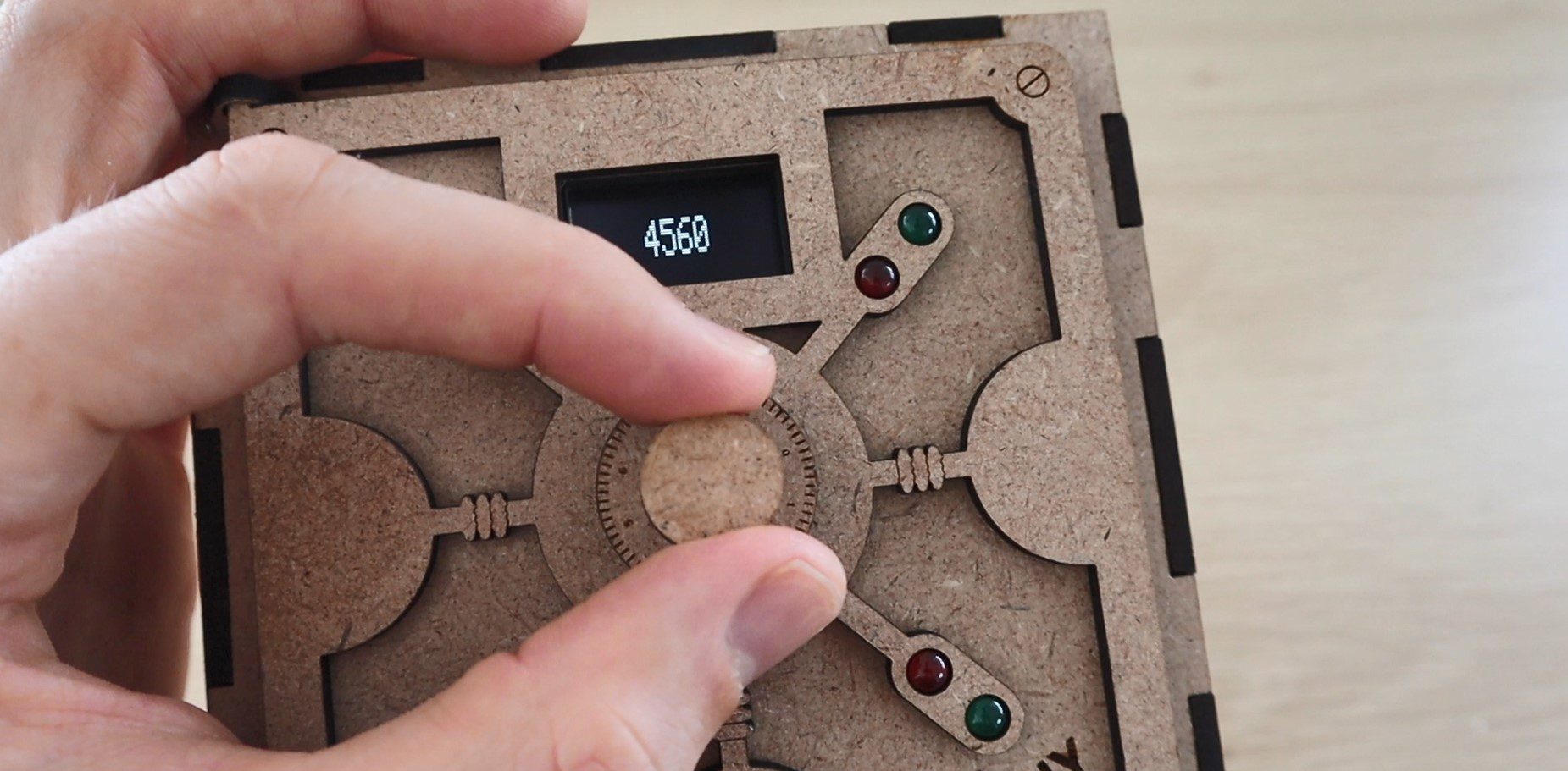
You then need to input the code by turning the dial to select the digits and pushing the dial to confirm each digit.
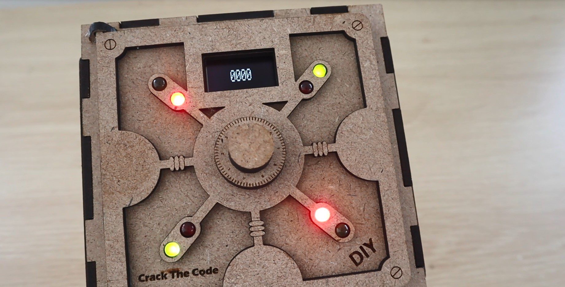
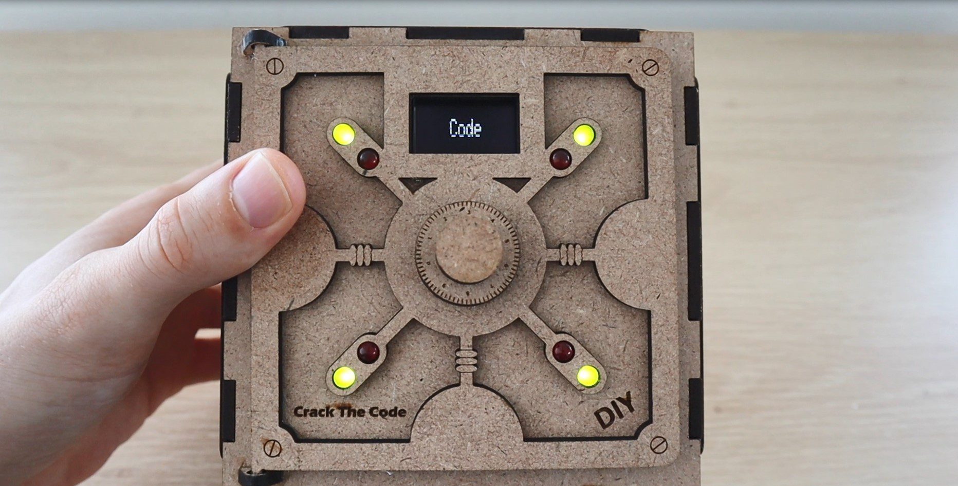
After your fourth digit is chosen, the safe displays how many of your digits are correct and how many of them are in the correct place using the red and green LEDs on the door. A red LED indicates a correct digit and a green LED indicate that it’s also in the correct place. So you’re looking to light up all four red and green LEDs in order to crack the code and open the safe.
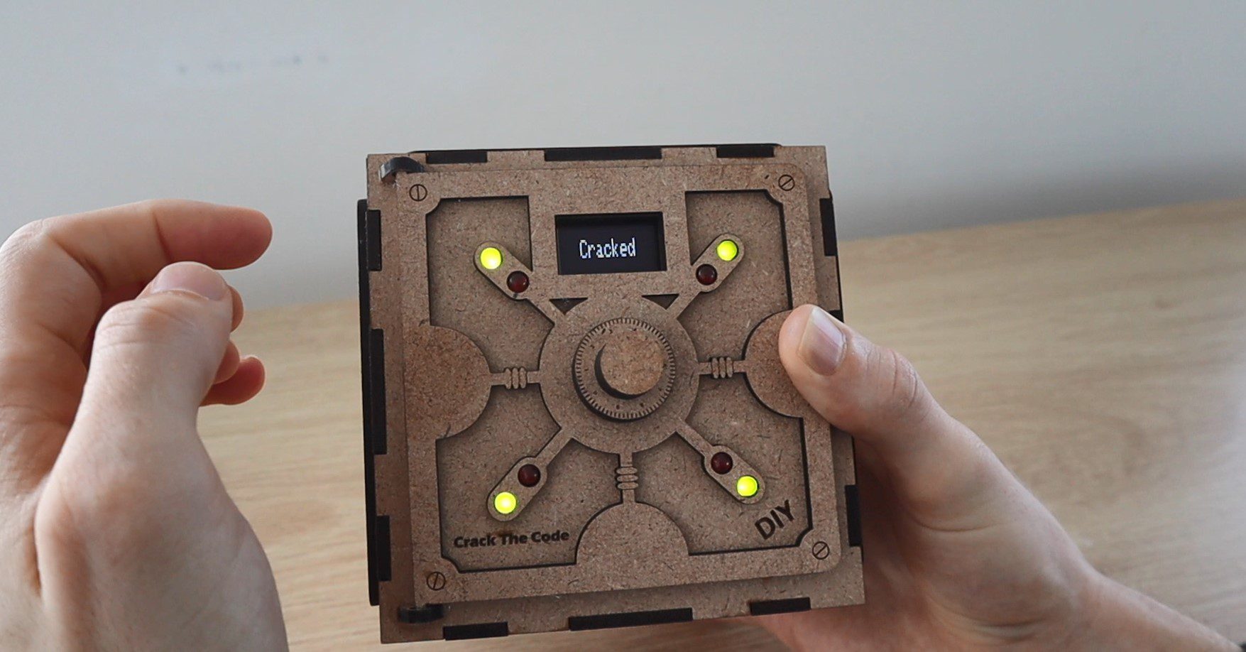
The safe keeps track of how many guesses you’ve made in order to crack the code. It may sound complicated at first but it’s actually not that difficult. You just need to remember and build upon your previous guesses. Most of the time you should be able to crack the code in 5 to 10 guesses, depending on how lucky your initial guesses are.
What You Need To Build Your Own Crack The Code Puzzle Box
In addition to these, you’ll also need some basic tools, a soldering iron, glue gun and some wood glue. You’ll also need to have access to a laser cutter to cut the box. If you don’t have access to one, consider using an online laser cutting service. There are quite a few options available and they’re quite affordable, they’ll even deliver to your door.
If you’re interested in a laser cutter, this is the one I’ve used for this project.
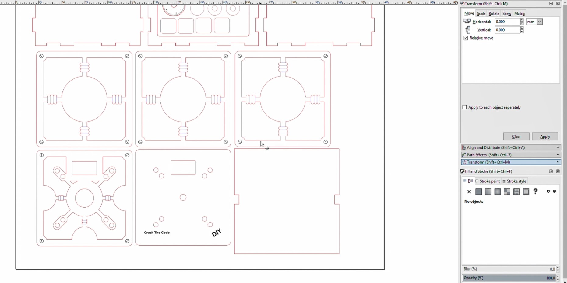
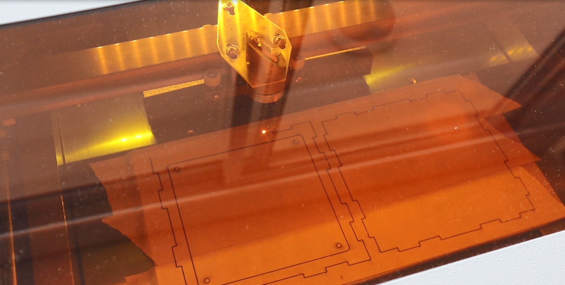
I started off by designing the safe box in Inkscape. It had to be large enough to house an Arduino Uno, have a compartment to put something into and look like a traditional safe. The pieces are designed to be cut from 3mm MDF, you could also cut the parts from 3mm acrylic or plywood. If you use a different thickness material then you’ll need to modify the edges of the box pieces so that the slots fit together.
The download above includes svg, dxf and A3 printable pdf files to give you a couple of options for cutting or printing.
There are 6 main panels which make up the box. The front panel has a cutout in it for the door and the back has one for the Arduino and battery compartment cover. The 6 main panels are labelled in the cutting file so that you’re able to identify them.
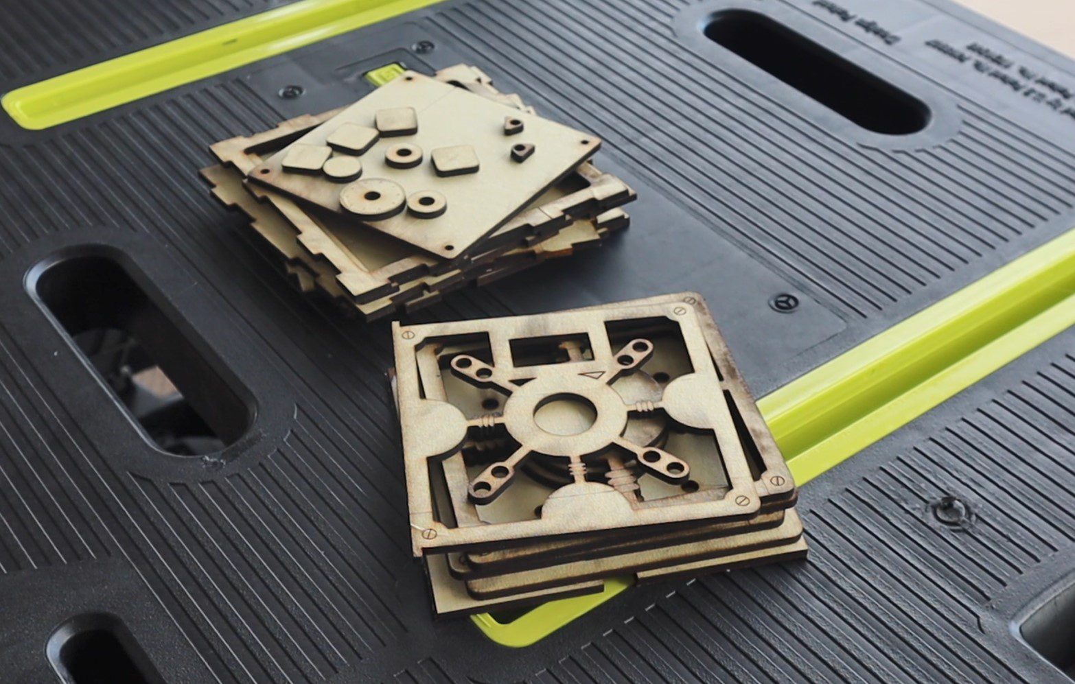
The dial is also made up from laser-cut pieces which are then glued together.
There are three decorative panels which are stuck onto the top and two sides of the box to make it look more like a safe. There are also two panels which make up the door and a divider panel which goes into the middle of the box to separate the safe compartment from the electronics compartment.
The pieces fit onto a single piece of MDF 400 x 500mm. They can be divided up into smaller pieces, as I’ve done, if your laser cutter isn’t big enough to cut them all in one go. I cut out two sections at a time.
Let’s cut out the pieces.
I used some masking tape to prevent the smoke from the laser from marking the wood. I had to take this off before gluing the box together, which is a little tedious but produces a much better end product.
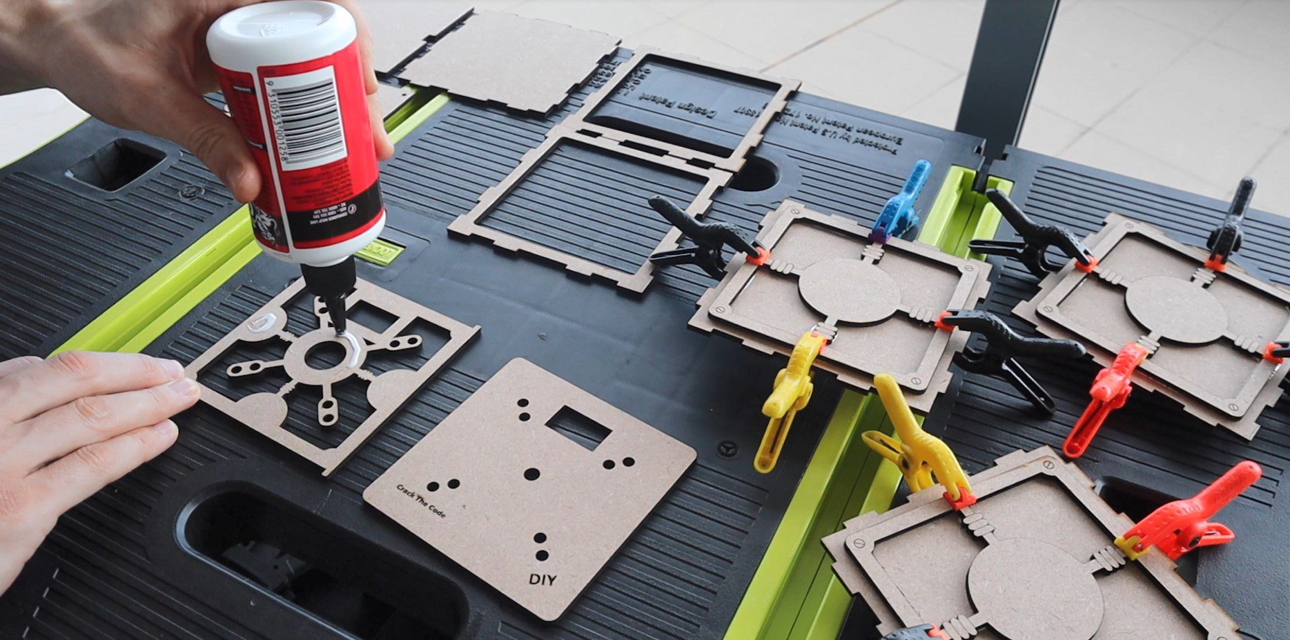
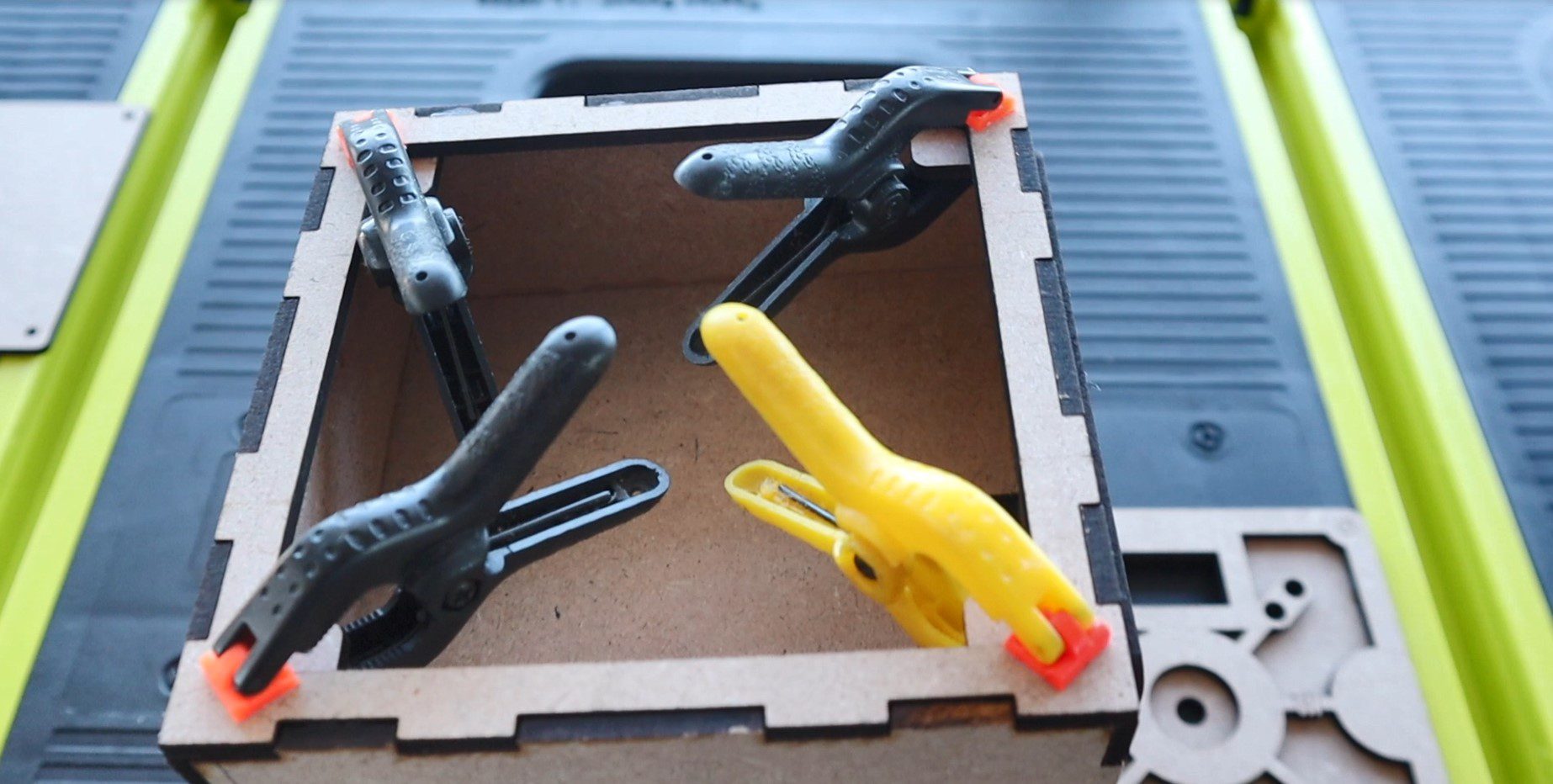
I started out gluing the decorative panels onto the top and sides first using some PVA wood glue and small plastic clamps. Make sure that you’ve got the pieces in the correct order so that you know which are which. There are three different pieces; the top and bottom are the same, the sides are the same and the front and back are the same. I’ve put text labels under each in the laser cutting file. Then glue the two door panels together.
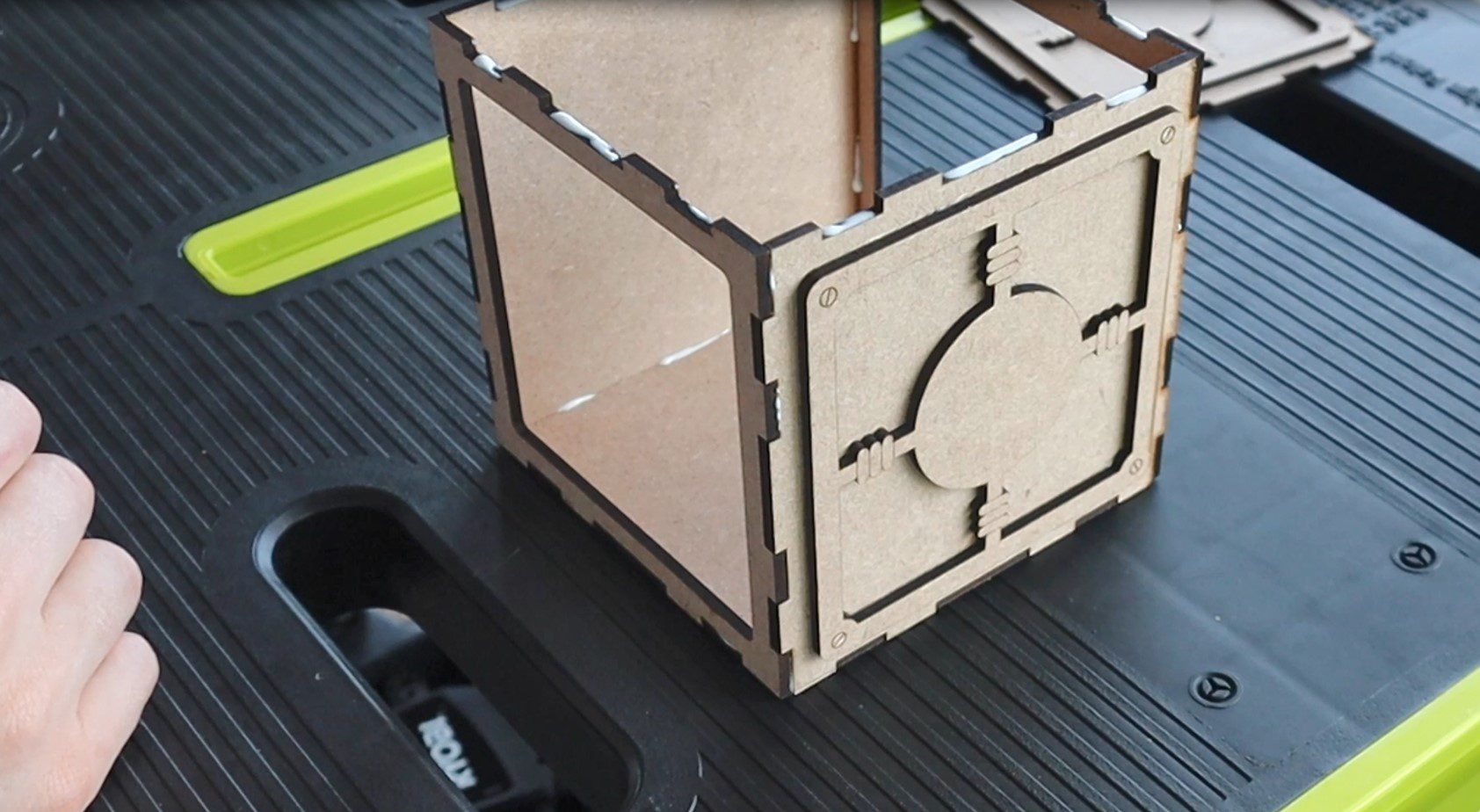
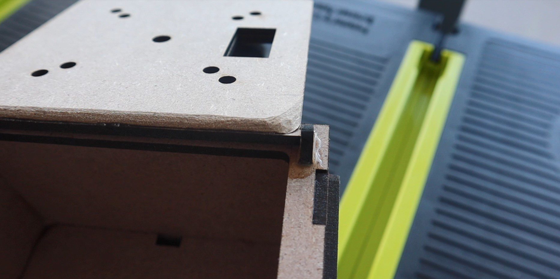
Once the panels are dry, you can assemble the box.
Make sure the cutouts for the centre divider are on the sides. These are to run any wires from the front of the box to the back of the box where the Arduino and battery sit.
The hinges are also laser cut and just glue into place once you’ve lined up the door. Make sure that they’re parallel to the door or you’ll have difficulty opening it. Also, make sure that the door is positioned over the centre of the cutout in the box so that there are no gaps visible.
You may also need to sand a little bit off of the inside hinged edge of the door once the hinges are dry so that it doesn’t rub on the inside edge of the box cutout as it moves past.
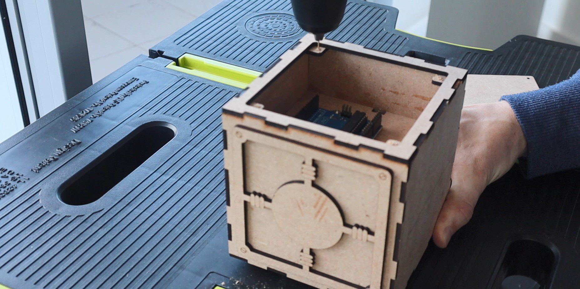
Glue the four square pieces into the corners behind the back panel to hold the screws for the back cover in place.
Then drill holes for the screws. I used a couple of spare screws I had lying around which came with the micro servos.
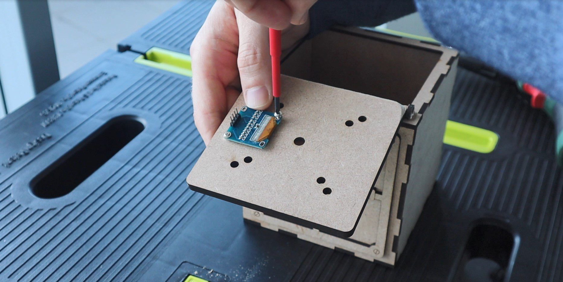
You can then mount the screen onto the door with two screws, the Arduino into the back compartment and lastly the encoder through the front door. The nut for the encoder is hidden by the recess provided by the front panel.
Connecting The Electronics
Now that the box is complete, we can start connecting the electronic components together.
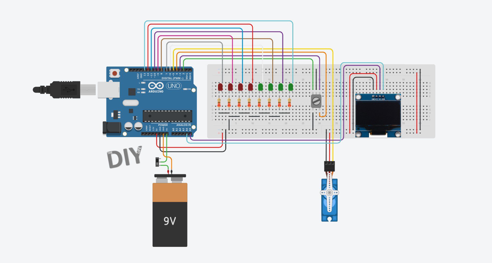
Here is the schematic:
We’ve got 8 LEDs connected to the digital IO pins 6 to 13. The locking servo connected to pin 5. The encoder connected to pins 2, 3 and 4 and the OLED display connected to the Arduino’s I2C interface.
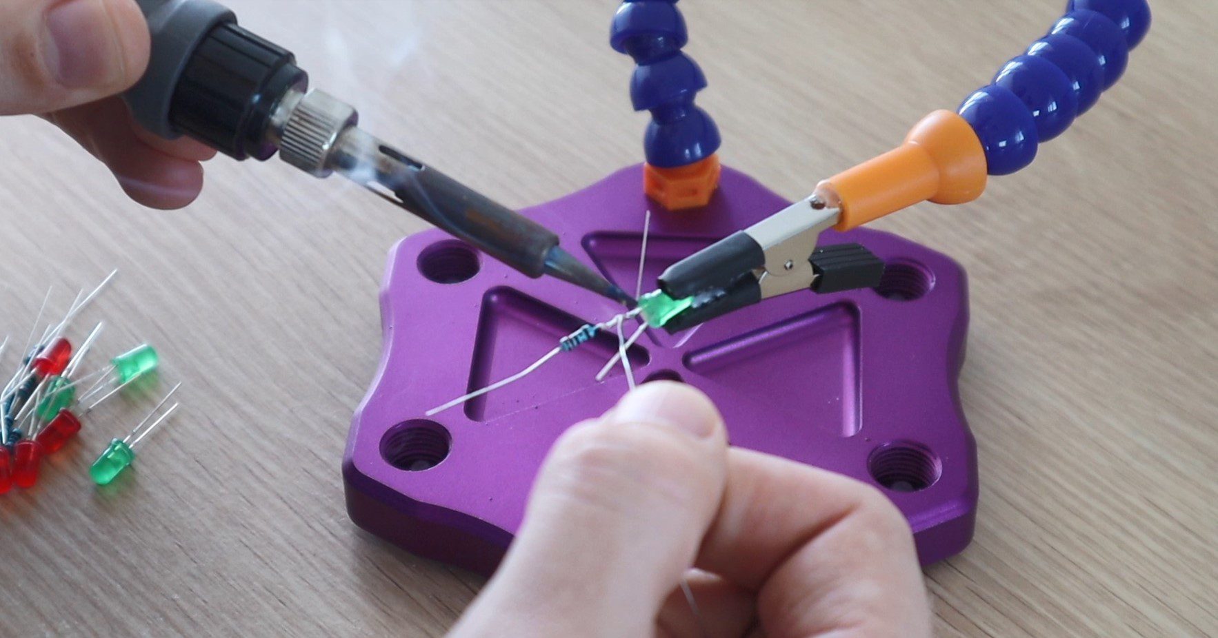
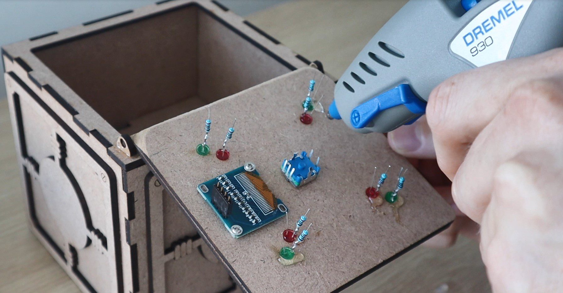
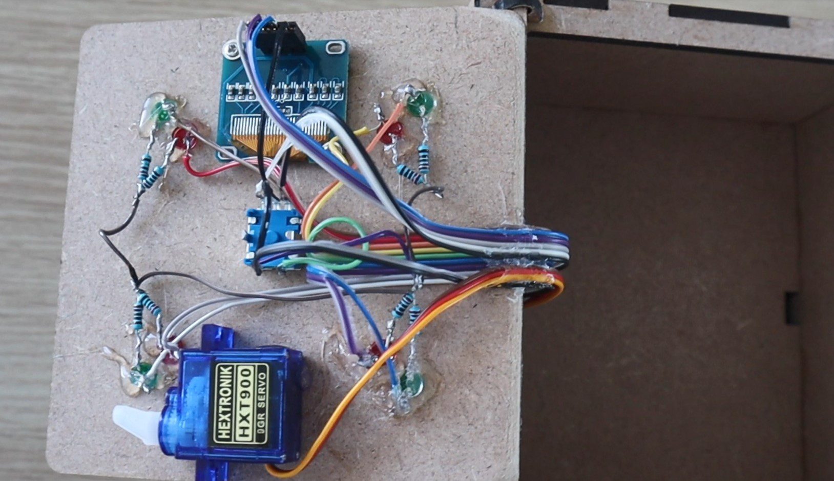
I used a 220 ohm resistor for each LED, which I soldered directly onto the cathode (negative pin) of the LED before gluing them into place with a glue gun.
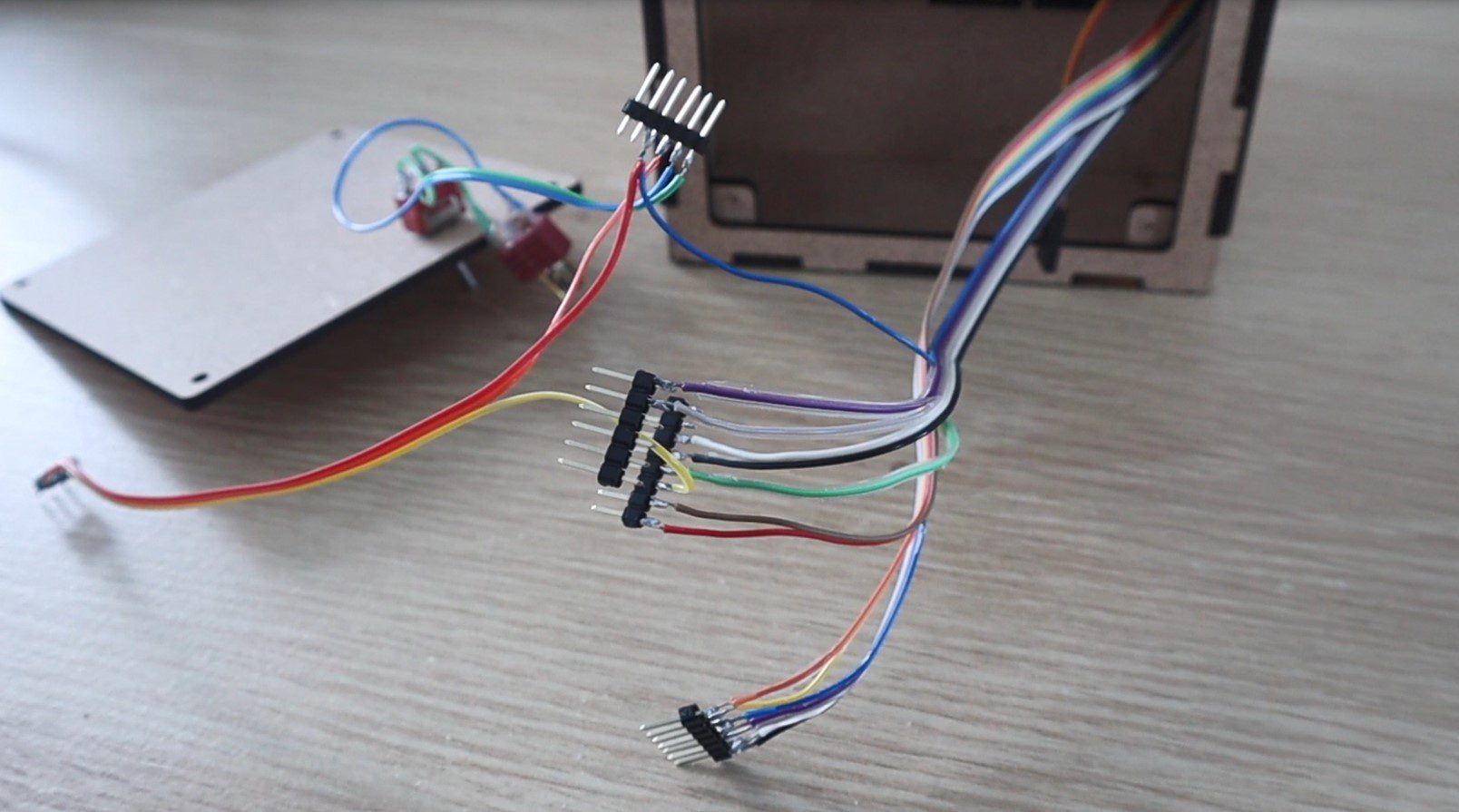
I connected the components together using coloured ribbon cable to keep the wiring neat and to help keep track of which wire needed to go to each Arduino pin.
I pushed the ribbon cables through to the back compartment and the soldered sections of header strips onto the ends to plug directly into the Arduino.
I also mounted a power switch onto the back cover and connected this to a battery plug to connect to a rechargeable battery to power the game. I used a 3 cell, 800mAh LiPo battery which I had from some RC aircraft. You could also use a 9V battery or a battery holder which houses 4 AA batteries.
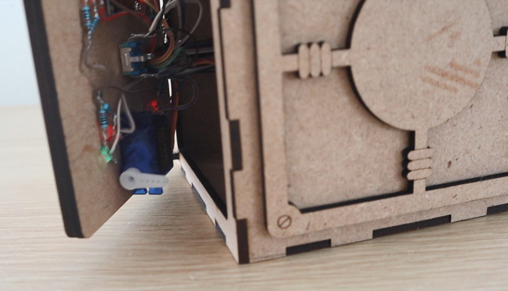
Lastly, you’ll need to mount the locking servo on the door. Position it towards the edge of the door so that it passes over the lip in the box and the arm is able to push up against the inside of the lip to lock the box. This isn’t the strongest locking mechanism but it is really simple and it works for the game’s purpose.
The safe box is now complete.
Coding The Game
The code for this game isn’t that complicated but is quite lengthy. I’ve tried to make the code as readable as possible by splitting it up into functions and putting in a lot of comments.
The code makes use of an interrupt routine to take the inputs from the rotary encoder, this is based on Simon Merrett’s example for a rotary encoder input which I found online. It was the most simple I could find and didn’t require any additional libraries to function.
Here is the code:
//Code Breaker
//Michael Klements
//The DIY Life
//15 May 2020
//Encoder interrupt routine adapted from Simon Merrett's example code
#include <SPI.h> //Import libraries to control the OLED display
#include <Wire.h>
#include <Adafruit_GFX.h>
#include <Adafruit_SSD1306.h>
#include <Servo.h> //Import library to control the servo
Servo lockServo; //Create a servo object for the lock servo
#define SCREEN_WIDTH 128 // OLED display width, in pixels
#define SCREEN_HEIGHT 32 // OLED display height, in pixels
#define OLED_RESET -1 // Reset pin # (or -1 if sharing Arduino reset pin)
Adafruit_SSD1306 display(SCREEN_WIDTH, SCREEN_HEIGHT, &Wire, OLED_RESET); // Declaration for an SSD1306 display connected to I2C (SDA, SCL pins)
static int pinA = 2; //Hardware interrupt digital pin 2
static int pinB = 3; //Hardware interrupt digital pin 3
volatile byte aFlag = 0; //Rising edge on pinA to signal that the encoder has arrived at a detent
volatile byte bFlag = 0; //Rising edge on pinB to signal that the encoder has arrived at a detent (opposite direction to when aFlag is set)
volatile byte encoderPos = 0; //Current value of encoder position, digit being input form 0 to 9
volatile byte prevEncoderPos = 0; //To track whether the encoder has been turned and the display needs to update
volatile byte reading = 0; //Stores direct value from interrupt pin
const byte buttonPin = 4; //Pin number for encoder push button
byte oldButtonState = HIGH; //First button state is open because of pull-up resistor
const unsigned long debounceTime = 10; //Debounce delay time
unsigned long buttonPressTime; //Time button has been pressed for debounce
byte correctNumLEDs[4] = {9,12,7,11}; //Pin numbers for correct number LEDs (Indicate a correct digit)
byte correctPlaceLEDs[4] = {6,10,8,13}; //Pin numbers for correct place LEDs (Indicate a correct digit in the correct place)
byte code[4] = {0,0,0,0}; //Create an array to store the code digits
byte codeGuess[4] = {0,0,0,0}; //Create an array to store the guessed code digits
byte guessingDigit = 0; //Tracks the current digit being guessed
byte numGuesses = 0; //Tracks how many guesses it takes to crack the code
boolean correctGuess = true; //Variable to check whether the code has been guessed correctly, true initially to generate a new code on startup
void setup()
{
Serial.begin(9600); //Starts the Serial monitor for debugging
if(!display.begin(SSD1306_SWITCHCAPVCC, 0x3C)) //Connect to the OLED display
{
Serial.println(F("SSD1306 allocation failed")); //If connection fails
for(;;); //Don't proceed, loop forever
}
display.clearDisplay(); //Clear display
lockServo.attach(5); //Assign the lock servo to pin 5
for(int i=0 ; i<=3 ; i++) //Define pin modes for the LEDs
{
pinMode(correctNumLEDs[i], OUTPUT);
pinMode(correctPlaceLEDs[i], OUTPUT);
}
pinMode(pinA, INPUT_PULLUP); //Set pinA as an input, pulled HIGH to the logic voltage
pinMode(pinB, INPUT_PULLUP); //Set pinB as an input, pulled HIGH to the logic voltage
attachInterrupt(0,PinA,RISING); //Set an interrupt on PinA
attachInterrupt(1,PinB,RISING); //Set an interrupt on PinB
pinMode (buttonPin, INPUT_PULLUP); //Set the encoder button as an input, pulled HIGH to the logic voltage
randomSeed(analogRead(0)); //Randomly choose a starting point for the random function, otherwise code pattern is predictable
display.setTextColor(SSD1306_WHITE); //Set the text colour to white
startupAni(); //Display the startup animation
}
void loop()
{
if(correctGuess) //Code between games to reset if the guess is correct, initially true to open safe and then generate new code
{
lockServo.write(140); //Unlock the safe
delay(300);
updateLEDs (0,4); //Flashing LED sequence
delay(300);
updateLEDs (4,0);
delay(300);
updateLEDs (0,4);
delay(300);
updateLEDs (4,0);
delay(300);
updateLEDs (4,4); //Turn all LEDs on
if(numGuesses >= 1) //Check that its not the start of the game
{
display.clearDisplay(); //Clear the display
display.setTextSize(1); //Set the display text size to small
display.setCursor(35,10); //Set the display cursor position
display.print(F("In ")); //Set the display text
display.print(numGuesses); //Set the display text
display.setCursor(35,20); //Set the display cursor position
display.print(F("Attempts")); //Set the display text
display.display(); //Output the display text
delay(5000);
}
display.clearDisplay(); //Clear the display
display.setTextSize(1); //Set the display text size to small
display.setCursor(35,10); //Set the display cursor position
display.print(F("Push To")); //Set the display text
display.setCursor(35,20); //Set the display cursor position
display.print(F("Lock Safe")); //Set the display text
display.display(); //Output the display text
display.setTextSize(2); //Set the display text size back to large
boolean lock = false; //Safe is initially not locked
boolean pressed = false; //Keeps track of button press
while(!lock) //While button is not pressed, wait for it to be pressed
{
byte buttonState = digitalRead (buttonPin);
if (buttonState != oldButtonState)
{
if (millis () - buttonPressTime >= debounceTime) //Debounce button
{
buttonPressTime = millis (); //Time when button is pressed
oldButtonState = buttonState; //Remember button state
if (buttonState == LOW)
{
pressed = true; //Records button has been pressed
}
else
{
if (pressed == true) //Makes sure that button is pressed and then released before continuing in the code
{
lockServo.write(45); //Lock the safe
display.clearDisplay(); //Clear the display
display.setCursor(30,10); //Set the display cursor position
display.print(F("Locked")); //Set the display text
display.display(); //Output the display text
lock = true;
}
}
}
}
}
generateNewCode(); //Calls function to generate a new random code
updateLEDs (0,0);
correctGuess = false; //The code guess is initially set to incorrect
numGuesses = 0; //Reset the number of guesses counter
}
inputCodeGuess(); //Calls function to allow the user to input a guess
numGuesses++; //Increment the guess counter
checkCodeGuess(); //Calls function to check the input guess
encoderPos = 0; //Reset the encoder position
guessingDigit = 0; //Reset the digit being guessed
codeGuess[0] = 0; //Reset the first digit of the code
updateDisplayCode(); //Update the displayed code
}
void updateDisplayCode() //Function to update the display with the input code
{
String temp = ""; //Temporary variable to concatenate the code string
if(!correctGuess) //If the guess is not correct then update the display
{
for (int i=0 ; i<guessingDigit ; i++) //Loops through the four digits to display them
{
temp = temp + codeGuess[i];
}
temp = temp + encoderPos;
for (int i=guessingDigit+1 ; i<=3 ; i++)
{
temp = temp + "0";
}
Serial.println(temp); //Output to Serial monitor for debugging
display.setTextSize(2); //Set the display text size
display.clearDisplay(); //Clear the display
display.setCursor(40,10); //Set the display cursor position
display.println(temp); //Set the display text
display.display(); //Update the display
}
}
void generateNewCode() //Function to generate a new random code
{
Serial.print("Code: ");
for (int i=0 ; i<= 3 ; i++) //Loops through the four digits and assigns a random number to each
{
code[i] = random(0,9); //Generate a random number for each digit
Serial.print(code[i]); //Display the code on Serial monitor for debugging
}
Serial.println();
}
void inputCodeGuess() //Function to allow the user to input a guess
{
for(int i=0 ; i<=3 ; i++) //User must guess all four digits
{
guessingDigit = i;
boolean confirmed = false; //Both used to confirm button push to assign a digit to the guess code
boolean pressed = false;
encoderPos = 0; //Encoder starts from 0 for each digit
while(!confirmed) //While the user has not confirmed the digit input
{
byte buttonState = digitalRead (buttonPin);
if (buttonState != oldButtonState)
{
if (millis () - buttonPressTime >= debounceTime) //Debounce button
{
buttonPressTime = millis (); //Time when button was pushed
oldButtonState = buttonState; //Remember button state for next time
if (buttonState == LOW)
{
codeGuess[i] = encoderPos; //If the button is pressed, accept the current digit into the guessed code
pressed = true;
}
else
{
if (pressed == true) //Confirm the input once the button is released again
{
updateDisplayCode(); //Update the code being displayed
confirmed = true;
}
}
}
}
if(encoderPos!=prevEncoderPos) //Update the displayed code if the encoder position has changed
{
updateDisplayCode();
prevEncoderPos=encoderPos;
}
}
}
}
void checkCodeGuess() //Function to check the users guess against the generated code
{
int correctNum = 0; //Variable for the number of correct digits in the wrong place
int correctPlace = 0; //Variable for the number of correct digits in the correct place
int usedDigits[4] = {0,0,0,0}; //Mark off digits which have been already identified in the wrong place, avoids counting repeated digits twice
for (int i=0 ; i<= 3 ; i++) //Loop through the four digits in the guessed code
{
for (int j=0 ; j<=3 ; j++) //Loop through the four digits in the generated code
{
if (codeGuess[i]==code[j]) //If a number is found to match
{
if(usedDigits[j]!=1) //Check that it hasn't been previously identified
{
correctNum++; //Increment the correct digits in the wrong place counter
usedDigits[j] = 1; //Mark off the digit as been identified
break; //Stop looking once the digit is found
}
}
}
}
for (int i=0 ; i<= 3 ; i++) //Compares the guess digits to the code digits for correct digits in correct place
{
if (codeGuess[i]==code[i]) //If a correct digit in the correct place is found
correctPlace++; //Increment the correct place counter
}
updateLEDs(correctNum, correctPlace); //Calls a function to update the LEDs to reflect the guess
if(correctPlace==4) //If all 4 digits are correct then the code has been cracked
{
display.clearDisplay(); //Clear the display
display.setCursor(20,10); //Set the display cursor position
display.print(F("Cracked")); //Set the display text
display.display(); //Output the display text
correctGuess = true;
}
else
correctGuess = false;
}
void updateLEDs (int corNum, int corPla) //Function to update the LEDs to reflect the guess
{
for(int i=0 ; i<=3 ; i++) //First turn all LEDs off
{
digitalWrite(correctNumLEDs[i], LOW);
digitalWrite(correctPlaceLEDs[i], LOW);
}
for(int j=0 ; j<=corNum-1 ; j++) //Turn on the number of correct digits in wrong place LEDs
{
digitalWrite(correctNumLEDs[j], HIGH);
}
for(int k=0 ; k<=corPla-1 ; k++) //Turn on the number of correct digits in the correct place LEDs
{
digitalWrite(correctPlaceLEDs[k], HIGH);
}
}
void startupAni ()
{
display.setTextSize(2); //Set the display text size
display.setCursor(35,10); //Set the display cursor position
display.println(F("Crack")); //Set the display text
display.display(); //Output the display text
delay(500);
display.clearDisplay(); //Clear the display
display.setCursor(45,10);
display.println(F("The"));
display.display();
delay(500);
display.clearDisplay();
display.setCursor(40,10);
display.println(F("Code"));
display.display();
delay(500);
display.clearDisplay();
}
void PinA() //Rotary encoder interrupt service routine for one encoder pin
{
cli(); //Stop interrupts happening before we read pin values
reading = PIND & 0xC; //Read all eight pin values then strip away all but pinA and pinB's values
if(reading == B00001100 && aFlag) //Check that we have both pins at detent (HIGH) and that we are expecting detent on this pin's rising edge
{
if(encoderPos>0)
encoderPos --; //Decrement the encoder's position count
else
encoderPos = 9; //Go back to 9 after 0
bFlag = 0; //Reset flags for the next turn
aFlag = 0; //Reset flags for the next turn
}
else if (reading == B00000100) //Signal that we're expecting pinB to signal the transition to detent from free rotation
bFlag = 1;
sei(); //Restart interrupts
}
void PinB() //Rotary encoder interrupt service routine for the other encoder pin
{
cli(); //Stop interrupts happening before we read pin values
reading = PIND & 0xC; //Read all eight pin values then strip away all but pinA and pinB's values
if (reading == B00001100 && bFlag) //Check that we have both pins at detent (HIGH) and that we are expecting detent on this pin's rising edge
{
if(encoderPos<9)
encoderPos ++; //Increment the encoder's position count
else
encoderPos = 0; //Go back to 0 after 9
bFlag = 0; //Reset flags for the next turn
aFlag = 0; //Reset flags for the next turn
}
else if (reading == B00001000) //Signal that we're expecting pinA to signal the transition to detent from free rotation
aFlag = 1;
sei(); //Restart interrupts
}
We start by importing libraries to control the OLED display and the servo. The libraries are used to drive the OLED display, you can find more information on driving these OLED displays on Adafruit’s page on using I2C OLED displays.
We then set the parameters for the display and create all of our variables.
I’ve separated the variables into sections and given each a comment to identify their function. There are quite a few variables dedicated to tracking the encoder turns as these are done through rising edge interrupts on pins 2 and 3. The LED pins are assigned through to arrays which make updating them a bit easier. There are two code arrays created, on to store the randomly generated code and one to store the user’s current guess. There are also a few variables to track whether the uses code is correct, which digit is currently being guessed and how many guesses the user has made so far.
In the setup function, we start the display, which won’t progress unless the connection to the display is successful. Then attach the servo, set the LED and encoder IO pin modes. We then make use of the randomSeed function which reads in from an open analog input in order to randomise the starting point for the random function. If we don’t do this then the randomly generated codes will follow a predictable pattern which we’ll soon be able to identify. Lastly, we display the Crack The Code text animation on the display.
The loop function flashes the LEDs and displays the message “push to lock safe” which then waits until the user pushes the dial to start the game. The same code is run at the end of a game which then displays the number of attempts and waits for a dial press to start a new game.
There is some debouncing code on the encoder pushbutton and once pushed, the servo locks the safe and a random code is generated. The code then calls a function to ask the user to input their guess and then another to check the guess, this is repeated until the user guesses the code correctly. After each code guess, we increment the number of guesses counter and reset the input code so that the user can select a code from 0000 again. You could also change this to carry on from the previous code again if you’d prefer.
There is a function to update the code being displayed, which is called every time the encoder is turned and the displayed code needs to change. This just loops through the code guess array and displays the four digits.
The function to generate a new code simply assigns a random digit to each of the four elements in the code array.
The function to input a code guess allows the user to select a digit using the encoder and then confirm each digit input by pushing the encoder down. The displayed code is updated after each button push and any time that the encoder position has been changed. So the encoder updates the position variable using the interrupt function and this portion of the code checks if the variable has been changed and then updates the code accordingly. The interrupt doesn’t directly drive any portions of the code, it only updates the encoder position variable.
The check code guess function then looks through the guessed code and decides how many digits are correct and how many are in the correct place. There is more code to the logic behind the digits in the incorrect place so that duplicates in the user’s input and in the generated code are managed. So if the user guesses 5555 and the code contains one 5 then only one of the red LEDs will light up. The same goes for the user guessing a single 5 in their code while the generated code contains two 5s, only one red LED will light up. The correct digit in the correct place check is a simple comparison of the digits in each position of the two arrays.
The update LEDs function switches the correct number of red and green LEDs on based on the output from the check code guess function.
The startup ani function displays the three-word “Crack The Code” animation on startup.
Lastly, two interrupt functions manage the input from the encoder, one incrementing the digit upwards when turned clockwise and one downwards when turned anticlockwise. These are both rising edge interrupts available on pins 2 and 3 of an Arduino Uno. These could also be set as falling edge or low level interrupts. You can read more on the Arduino’s available interrupts if they interest you.
Now let’s upload the code and try it out.
Edit: Modify Code To Start With Locked Box
I’ve had quite a few people ask about how to start the box off locked rather than with the current push to start the game and lock the box. This is quite easy to change, you just need to modify three lines:
Add lockServo.write(45) into the setup function (at the end) to lock the safe when the box is turned on.
Move line 73 – lockServo.write(140) into the if statement below it (at the beginning). The statement starting on line 84, so insert it into line 86. This will then only unlock the box again once the guess is correct.
Change the displayed text in line 101 to read display.print(F(“Start”)). As the box will already be locked on startup.
This will then start the box off locked. You’ll still need to press the encoder to start the game but this won’t do anything to the lock in the first round as it will already be locked. In subsequent games, starting the game will lock the box again.
Playing The Game and Trying To Crack The Code
The guessed code is input using the dial to increment the digit and a push on the dial to go to the next digit or to confirm the code once all four digits are selected.
The LEDs on the front then light up to tell us what was correct in our guess. The red LEDs indicate that you’ve got a correct digit but not necessarily in the correct place and the green LEDs indicate that the digit is also in the correct place. The position or order of the LEDs is meaningless, they don’t give you any further information. Remember that you’ll need to be careful with double digits as the LEDs don’t light up multiples times for repeated digits unless you’ve repeated the digit in your guessed code.
The safe is initially unlocked, allowing you to put something inside it.
We then push the dial to lock the safe and generate a new code. You then have to try and figure out the code in order to open the safe again.
Once you’ve cracked the code, the box will unlock and display the number of attempts it took you to unlock it.
The easiest way to see how the game is played is to watch the video at the beginning which has two demonstrations near the end.
Enjoy building your own crack the code safe box. Let me know how it goes for you or what changes you’ve made to it in the comments section.
Community Builds
Asaf Matan has made some fantastic modifications to the puzzle box to make the storage area a little larger, separate the electronics and to run on an ESP32 instead of an Arduino. Take a look at his blog post for the code and some additional build images:
The term “cylinder lock” could mean a large number of different locks, but in today’s guide, we will focus on one type of cylinder – the Euro cylinder. The Euro cylinder was first patented in 1805 and was an attempt by European locksmiths to standardise locks, which, in Europe and other parts of the world has been largely successful. Euro cylinders are now a common sight on the external doors of many homes. In the United States, Euro cylinders are used primarily on sliding glass doors and internal doors which divide two rooms.
Euro cylinders are easy to change or upgrade, and here at The DIY Life, we love to save you both time and money. There is no need to call a locksmith or handyman as these are one of the easiest locks to change, due to the cylinder being self-contained, their standardisation and wide availability. In fact, the most important part is the preparation.
To Change A Euro Cylinder You Will Need
1 Phillips Screwdriver OR 1 Torx Screwdriver (depending on the screw type)
1 Euro Cylinder Lock (Do NOT BUY before you have extracted the lock as you need the correct size)
Your existing Euro cylinder key
How To Change The Lock
1. Firstly open the door so you can comfortably stand by the side of it.
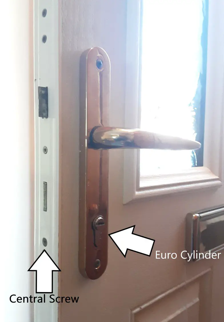
2. Next, locate the Euro cylinder on the door, then locate the central screw on the side of the door. This is the screw that keeps the Euro cylinder in place.
3. Identify which screwdriver is appropriate to use, then remove the screw. Normally this will be a Phillips, but may also be a Torx screw and very rarely may be a flat head.
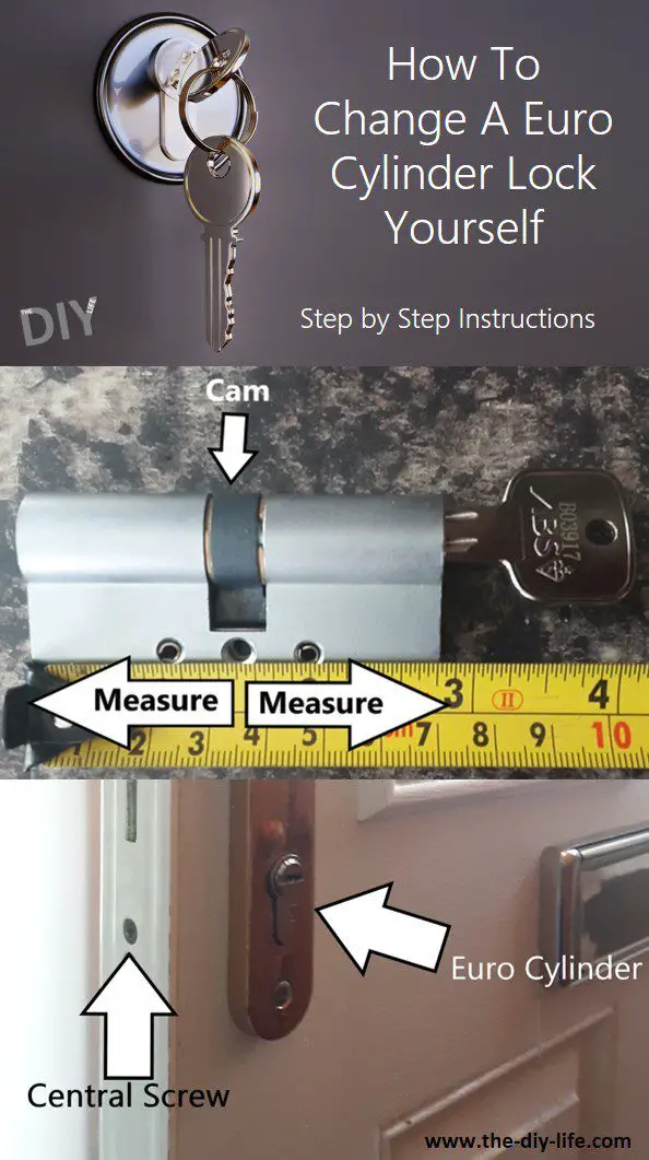
4. Once the screw is removed, insert your key into the lock and turn it about an 8th of the way or to approximately to 2 O’clock, this is to align the cam (middle of the lock). Once aligned, pull the key and lock towards you until you feel a release. You sometimes need to loosen the screws to the door handle to make this easier, but will not usually be necessary. This can be a bit tricky, but just remember, all it is is an alignment issue. Loosen the door handle, turn the key to align the cam and wiggle the lock out.
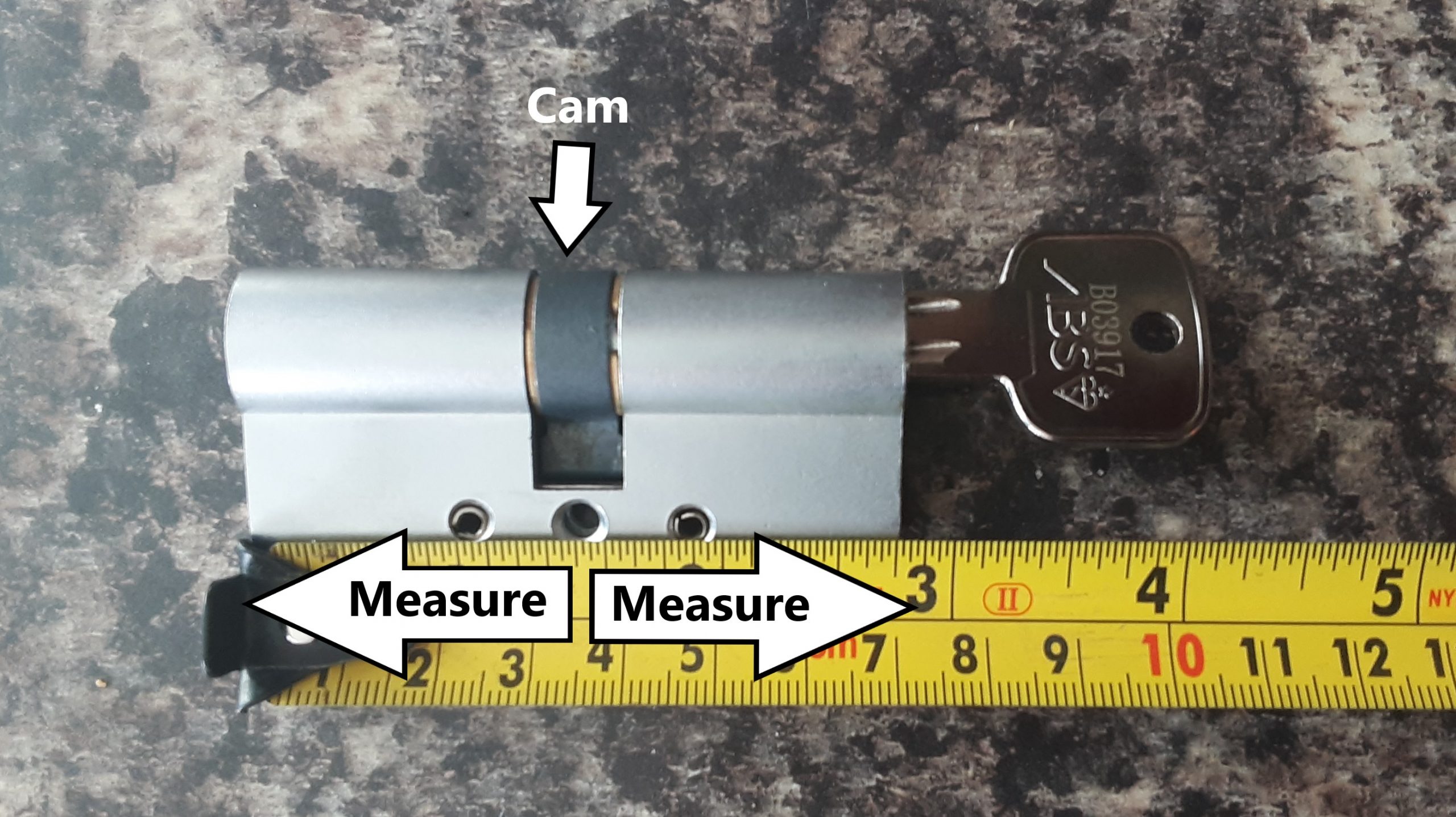
5. Now the Euro cylinder should be in your hand, giving you the opportunity to measure it. You can measure the size of a Euro cylinder by finding the central screw hole on the lock. Grab a tape measure and measure from the central screw hole to the end of the cylinder, measure both ways. Your measurement should be something like 35mm by 35 mm (As seen below) or 45mm by 50mm etc. However, this size is only correct if your lock is the correct size for the door in the first place. The cylinder should be flush to the door with none of the cylinder being exposed. If the cylinder is exposed then measure from the central screw hole to where the lock would fit flush to the door, this should be identifiable with a weathered line on the lock, where some of the lock has been exposed to the elements. This exposure of the lock is a serious security risk and makes bypassing the lock much easier with a technique called lock snapping (more on that later).
6. There are approximately 25 different sizes, so ensure you have measured the size correctly. Alternatively, if possible, you could take the lock with you to ensure you purchase the exact size needed.
7. Now travel to your local hardware store and purchase the correct size replacement cylinder.
8. Once you have the new cylinder, insert your new key into it and turn it an 8th of the way, so the cam (the middle) is aligned, allowing you to insert the lock into your door. The exact same way you took it out but in reverse. This bit can be as tricky as getting the lock out, remember it’s just an alignment issue so just fiddle around and it will eventually come right.
9. Once the lock is fitted nicely and is flush with the door, use the old screw you took out of your previous lock and insert it into the central screw hole and tighten it. We recommend using the old screw as it will be the correct length, sometimes a new screw will be too long and will have to be cut to size. Alternatively, if the new screw is the same size and doesn’t require cutting, then use the new screw. Don’t forget to keep your cylinder measurement for future maintenance.
10. To test that it has all been done correctly, lift the handle and turn the key to lock the lock with the door open. Lock the cylinder a few times to test it. Once you have seen this working it properly, it should be safe to shut the door and lock it.
Euro cylinders are great locks and are renowned for being difficult to pick, however, they do possess some natural weaknesses. one big vulnerability to the security of your door is called snapping. Lock snapping is exactly what the name suggests, it literally means snapping the lock in two. The scariest thing is that this technique can be successfully done in as little as 15 seconds, and the tools required to snap a lock can be found almost anywhere. This can be overcome by purchasing anti-snap locks with a sacrificial section. Instead of the lock snapping in half, the sacrificial section will break off leaving the rest of the lock within the door, safe from another snapping attempt.
Another vulnerability of the euro cylinder is drilling. Like most locks, the Euro cylinder can be drilled within minutes. While this cannot be overcome, you can purchase euro cylinders with anti-drill pins within them. This does not stop drilling, but it does make drilling a harder and longer process.
Generally higher quality Euro cylinders are made out of stronger and sturdier materials, they also contain more anti-drill pins, in addition to other security feature,s such as anti-bump pins, sacrificial sections and magnetic operating locks, making picking extremely difficult. If your Euro cylinder is for an external door you should consider purchasing a high-security lock, as this will be much more resistant to any bypassing techniques used by criminals, making it harder for them to enter your property. More on this and other helpful security tips and advice can be found on ITCC Locksmith’s blog section.
Have you tried changing your own Euro cylinder lock? Let us know in the comments section below.
Few home decor accessories look as regal as a chandelier. The problem is that chandeliers usually cost a pretty penny. Whether you’re on a budget or just looking for a new home improvement DIY project, making your own chandelier is fun, easy, and surprisingly affordable.
As you read this guide on chandelier making, remember that these are just suggestions and not requirements. You can use the basic design as-is, or feel free to get creative and modify it to fit your unique style preferences. The possibilities are endless!
1. Gather Materials
If you do a lot of DIY projects, there’s a good chance you’ll already have a lot of these materials lying around the house. If not, you should be able to obtain them fairly easily—check hardware, junk stores, and other retailers that sell lamp and light fixture parts.
If you’re struggling to find a particular item, try to think outside the box. You should be able to come up with a solution, even if it’s not exactly what you initially had in mind.
Here’s a general idea of what types of materials you’re going to need:
A top base to hold the suspended items (repurposed wood, a bicycle wheel, or a wire cooking rack are all great choices)
At least 10 feet of lightweight wire lamp chain or other lamp cord
14-gauge (1.5mm^2) wire
At least six small Mason jars (or exposed light bulbs of your choice)
A one-inch circular metal ring
A swag hook or other hardware for hanging the chandelier
Pliers
Wire cutters
2. Attach the Chains or Cord to Your Top Base
The metal ring is going to be your point of contact to the ceiling. When you’re finished with your chandelier, you can use the ring to hang it from a hook. Start by using your wire cutters to cut the lamp chain or cord into four equal-sized pieces. The length depends on the size of your base, but around 16 (400mm) to 24 (600mm) inches should do the trick.
If you’re using chains, take your pliers and open the top link of each chain. Attach the chain to the metal ring, and then use your pliers to squeeze the chainlink back into place. Repeat this step for all four chains. You should end up with four equal lengths of chain hanging from the ring.
If you’re using a flexible cloth-covered cord, consider wrapping the material around your base in a way that matches the aesthetic you’re going for.
3. Attach the Cord to the Base
Now you’re going to repeat the same process to attach the bottom of the chains to your wheel, wire cooking rack, or other base. If your base is thicker than your chain links, you might need to get creative. You could use wire to wrap the bottom chain link to the perimeters of your base.
When you’re done attaching all four chains, you should be able to hold the top ring, and the base should hang evenly. If it’s crooked, you might need to trim the chains to make sure they’re all the exact same size.
4. Create Wire Handles on the Jars
Credit: Color Cord Company
Next, you’re going to create wire ‘handles’ so you can hang each jar from the base. Cut your wires so they’re 24 inches (600mm) long. Wrap the wire securely around the lip of your Mason jars, leaving at least 8 inches (200mm) of slack like a tail. You’ll attach the other end of the wire ‘tail’ to the jar eventually, but not yet.
Pro tip: You could also leave the lids on, drill a hole in the tops of the lids, and attach the jars directly to the base using rope or twine for a rustic look. Simply thread it through and tie a knot in the bottom to prevent it from slipping out.
5. Thread the Wires Through the Bottom Chain Links
Cut six (or more) pieces of lamp chain to hang the jars. You can cut the chains into random lengths, or measure them if you want a symmetrical design. Now it’s time to thread the ‘tail’ of the wire handles on your jar through the bottom chain links. Secure the end of the wire to the other side of the jar, creating a U-shaped handle. Repeat these for all of the jars.
6. Attach the Jars to the Base
Now you have six or more jars with chains attached. You might need a friend for this next step. Hang your base from the ceiling, and attach the top of the chains to the base, one-by-one. Be sure to position them in areas that keep the weight of the structure balanced. It’s important to attach the jars while the chandelier is hanging, otherwise, you risk it being lopsided.
7. Add More Flair
You can leave the chandelier as-is if you want a classic, bucolic look. Minimalism is a popular architecture trend, so feel free to keep it simple. For a stronger visual effect, you could use your leftover light cord or chain to hang beads, crystals, shells, ornaments, antique bottles, or anything else that catches your eye. Feel free to get creative with it.
If you really want to make your new chandelier pop, consider painting it. A quick coat or two of spray paint will help to transform an old wheel or baking rack into a more realistic base. A coat of white paint is a safe and elegant option, but don’t be afraid to match it to your home’s unique colour scheme.
8. Light It Up
Congratulations, your chandelier is finished! The last step is to light it up and enjoy. If you’re using candles, simply light them and drop them into the jars. Just make sure you follow candle safety guidelines to prevent fires.
If you prefer electricity, you could also consider using lamp parts and an extension cord or even wireless LEDs to add bulbs to the jars. Or, you could consider hanging your chandelier underneath an existing ceiling light fixture so the light can radiate off the glass naturally. Be sure to follow electrical safety guidelines if you’re doing any wiring on your own, or hire a contractor to help you with wiring your new light fixture.
Note: Make sure that you check your local regulations before doing any electrical work, some area do not permit unlicensed electrical work to be carried out.
Keep Adding To Your Chandelier
The great thing about this project is that you can keep modifying it over time. Just keep some spare chain and wire on hand, and you’ll be able to attach new pieces whenever the mood strikes. If your first chandelier doesn’t turn out as well as you were hoping, learn from your mistakes and try again! The materials are cheap, so why not experiment with your design?
Have you tried making your own chandelier? Let us know what you made in the comments section below.