Today we’re going to be having a look at two members of the M5 range, the M5Stack Core 2 and the M5StickC Plus. These are feature-rich ESP32 based development boards that enable you to develop and prototype your own projects and IoT devices without a significant learning curve.
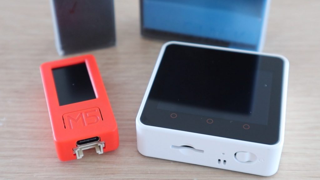
These devices both have colour displays, with the Core 2’s being a touch screen, as well as some additional buttons, built-in batteries, IO headers and a range of sensors, like microphones and IMUs built into them.
Here’s my video of the unboxing and tinkering with the two development boards:
Where To Buy The M5Stack Core 2 and M5StickC Plus
These two boards were sent to me by Banggood to share with you, you can get your own through the below links:
- M5Stack Core 2 – Buy Here
- M5StickC Plus – Buy Here
- M5 Sensor Pack – Buy Here
- Grove Connector Cable Pack – Buy Here
In addition to these boards, the following accessories were used here:
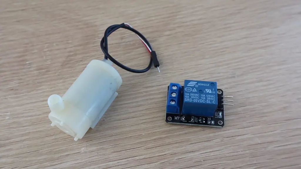
- 8 Channel Relay Board – Buy Here
- Joystick- Buy Here
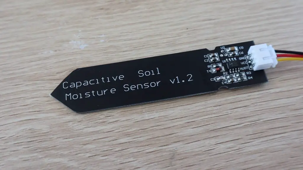
- Capacitive Soil Moisture Sensor- Buy Here
- Jumpers- Buy Here
The above parts are affiliate links. By purchasing products through the above links, you’ll be supporting my projects, with no additional cost to you.
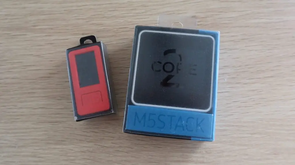
Unboxing The M5StickC Plus
Let’s open up the M5StickC Plus first and take a look at that.
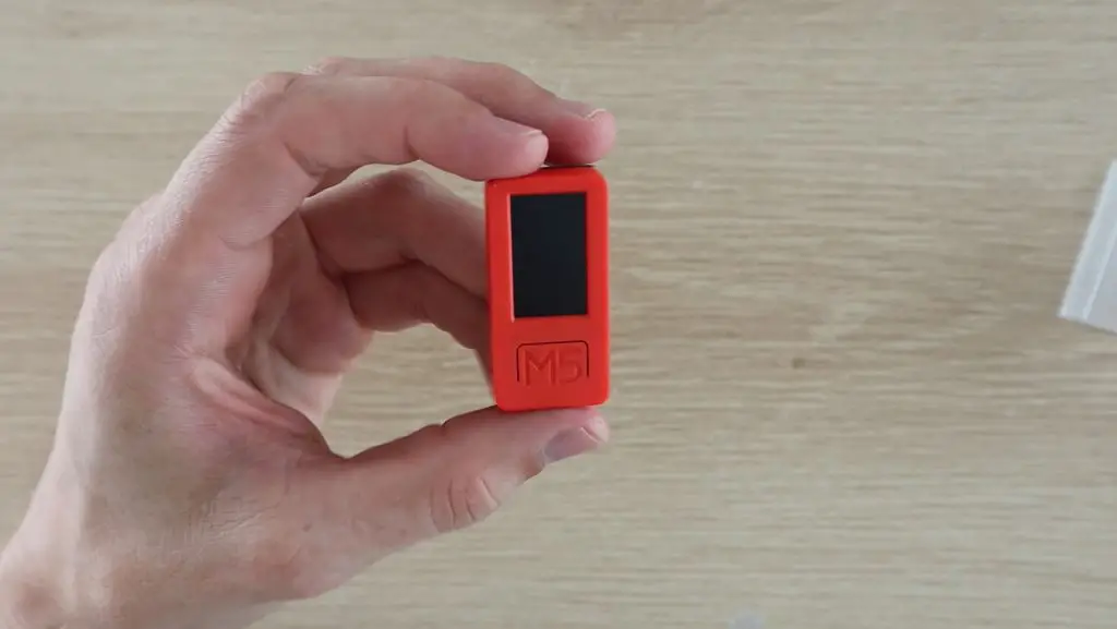
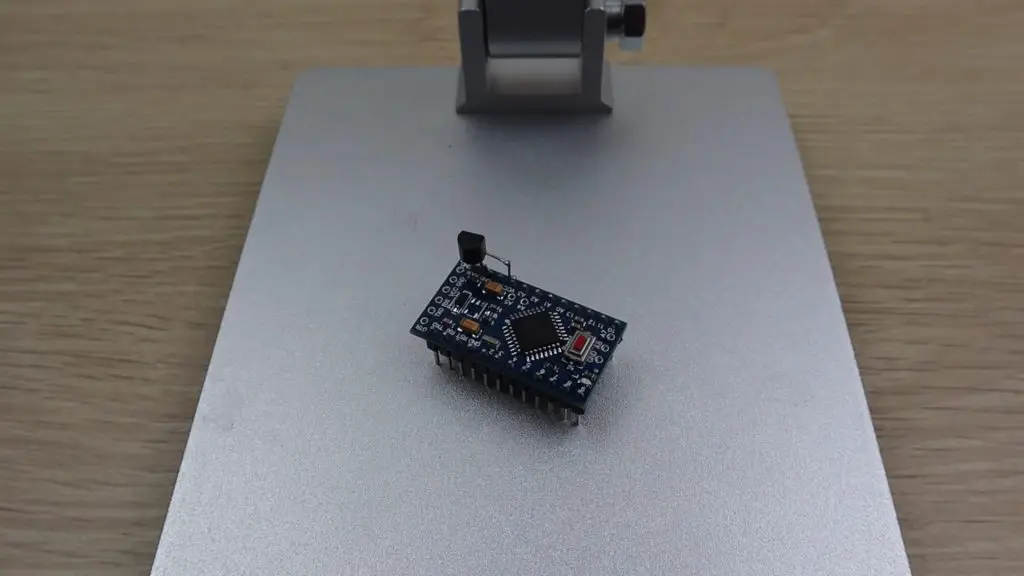
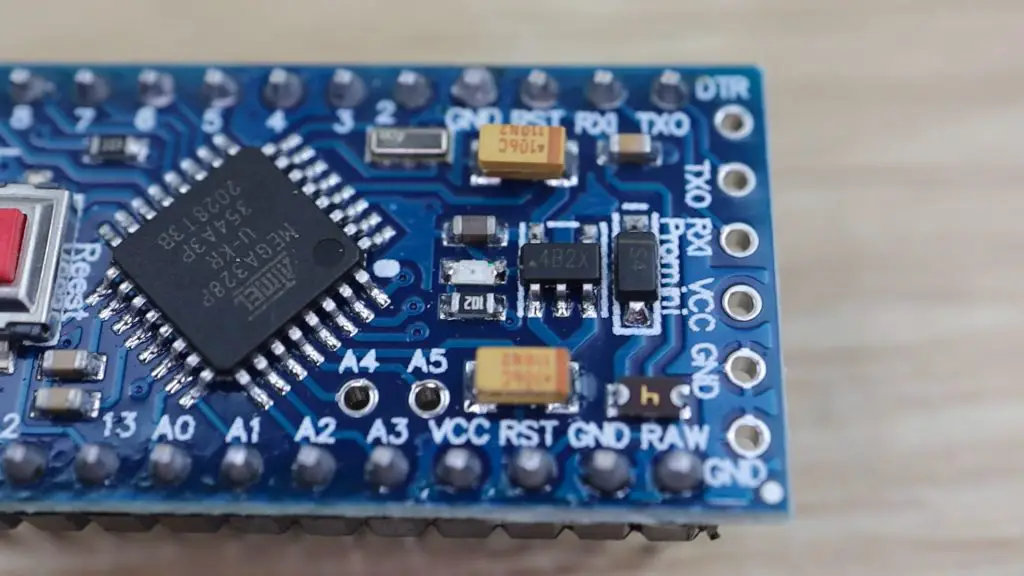
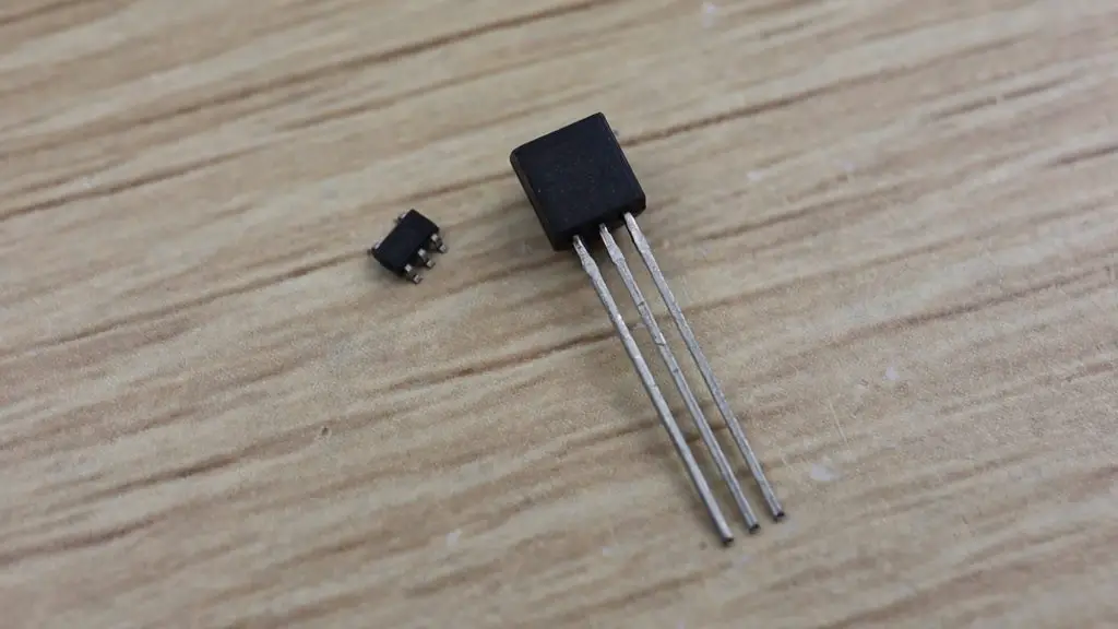
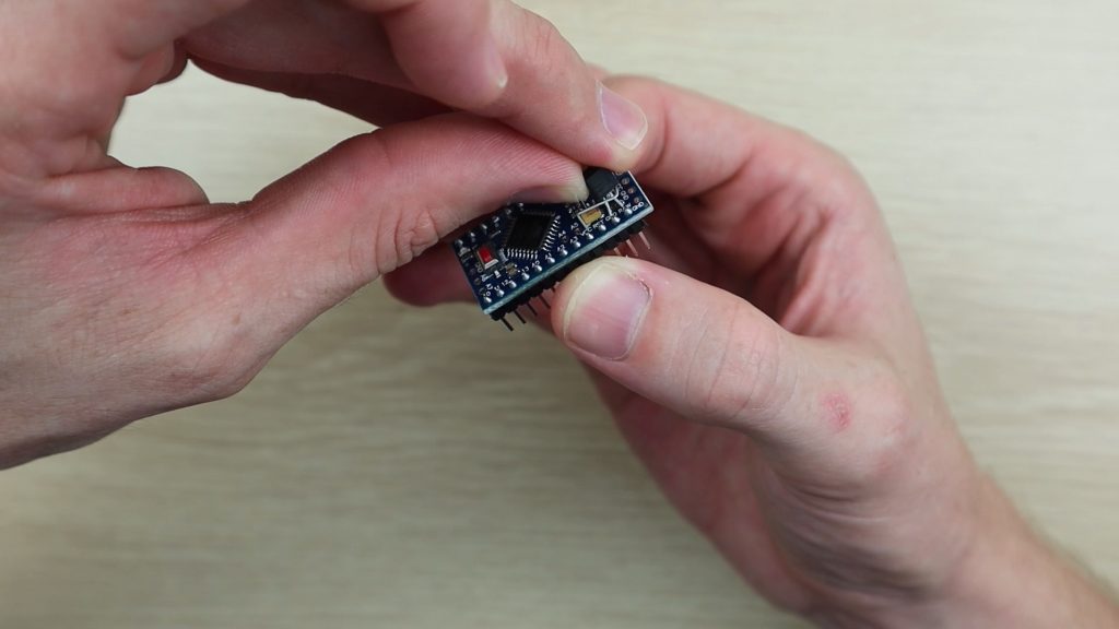
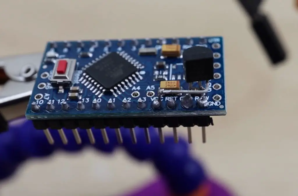
I’ll start off by saying that this device is really small for what it is able to do. It’s a little bit bigger than an Arduino Nano, and obviously a bit thicker to accommodate the sensors and battery, but it’s really compact for what they’ve managed to fit into it.
It’s got a 1.1 inch TFT display, with two customisable buttons and a separate power button.
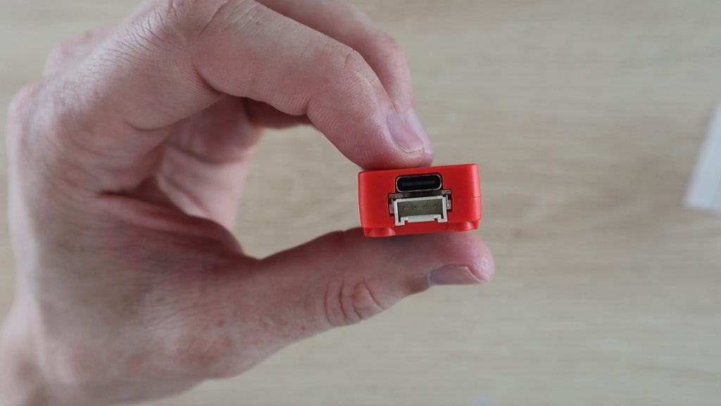
It’s got an IO expansion port on the top which has a range of power supply and input options as well as access to four IO pins. It’s also got a grove connector on the bottom to add compatible devices and sensors.
This USB C port is used to charge and program it.
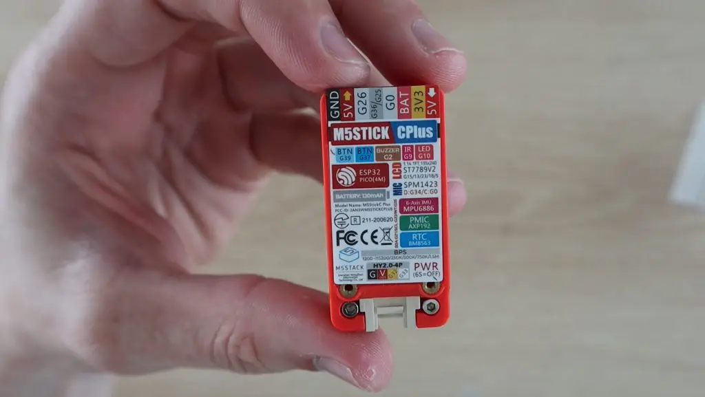
In addition to these features on the outside, the stick has a built in LED, buzzer, 6 axis MPU, IR transmitter, microphone and real time clock. It also has both dual-mode bluetooth and WiFi connectivity.
So this is a really powerful little device.
Specifications:
| ESP32 | 240MHz dual-core, 600 DMIPS, 520KB SRAM, Wi-Fi, dual-mode Bluetooth |
| Flash Memory | 4MB |
| Power Input | 5V @ 500mA |
| Ports | USB Type C x 1, GROVE (I2C+I/0+UART) x 1 |
| LCD Screen | 1.14 inch, 135*240 Colorful TFT LCD, ST7789v2 |
| Button | 2 x Custom Buttons |
| LED | RED LED |
| MEMS | MPU6886 |
| Buzzer | Built-in Buzzer |
| IR | Infrared Transmission |
| MIC | SPM1423 |
| RTC | BM8563 |
| PMU | AXP192 |
| Battery | 120 mAh @ 3.7V |
| Antenna | 2.4G 3D Antenna |
| PIN Ports | G0, G25/G36, G26, G32, G33 |
| Operating Temperature | 32°F to 104°F ( 0°C to 40°C ) |
| Net Weight | 15g |
| Gross Weight | 21g |
| Product Size | 48.2*25.5*13.7mm |
| Package Size | 65*25*15mm |
| Case Material | Plastic ( PC ) |
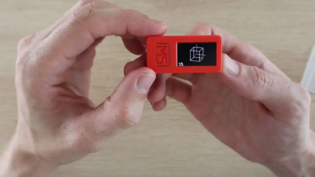
Preloaded Demo Program
The M5StickC Plus comes with a pre-loaded basic demo program, there’s a sample clip of this program included in my video at the beginning. The program demonstrates the use of the MPU, real-time clock, microphone, IR transmitter and Bluetooth connectivity.
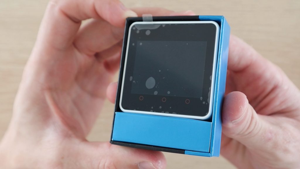
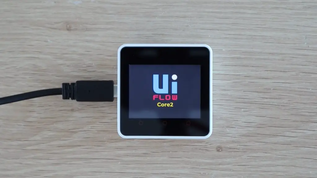
Unboxing The M5Stack Core 2
Next let’s open up the M5Stack Core 2 – this is an upgrade to the original M5Stack Core.
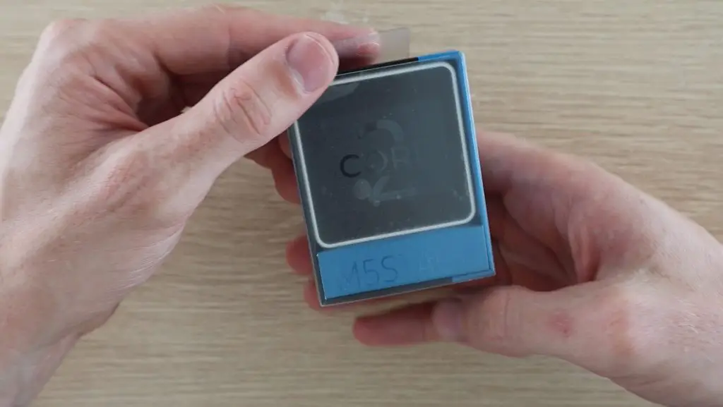
The Core 2 has a 2-inch display, which is also a touch screen. It also has three capacitive touch button below the display, which replace the physical buttons on the original core.
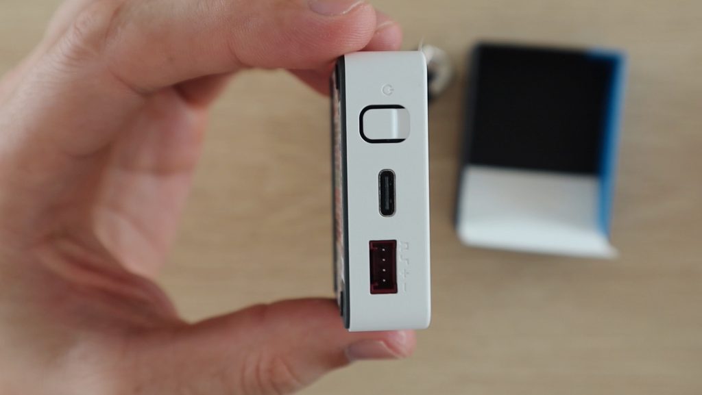
We have two buttons on the side, one for power and one to reset the device. And then we also have a USB C port, Grove connector and microSD card slot.
Beneath the case, we’ve also got an LED, microphone, vibration motor, speaker, 6 axis MPU and real-time clock.
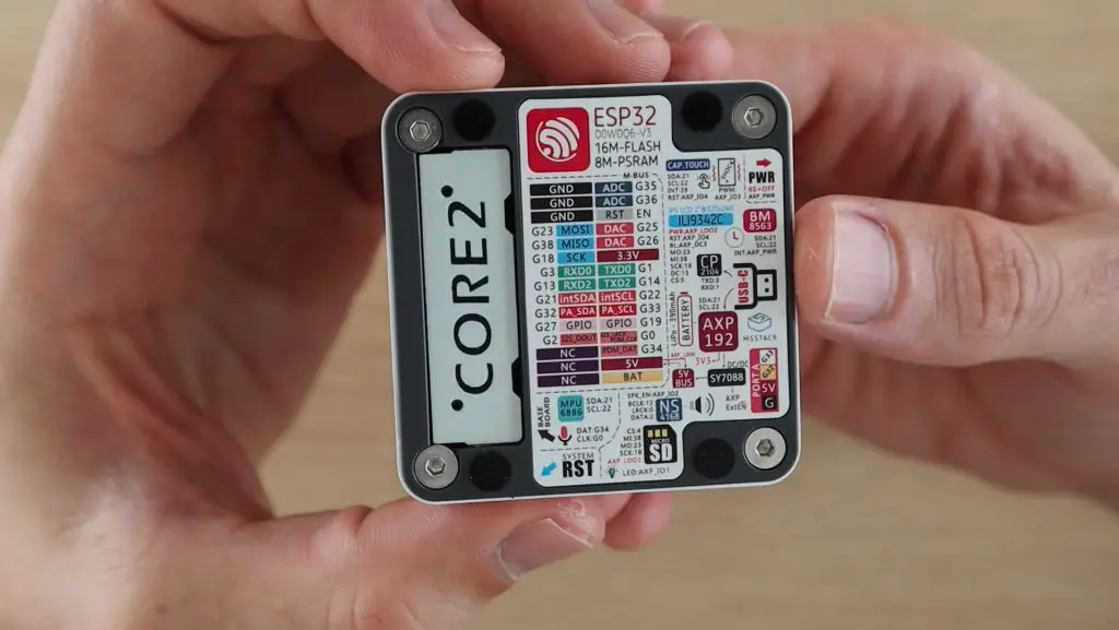
This cover on the back hides the 30 header pin socket which allows you to access a range of IO and communication pins, which are detailed in the diagram alongside it.
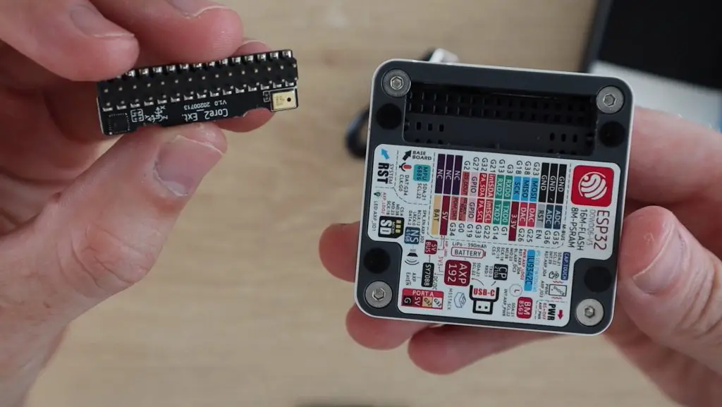
This port also allows you to plug in other M5Stack modules to build a stack, which is where the device get’s it’s name.
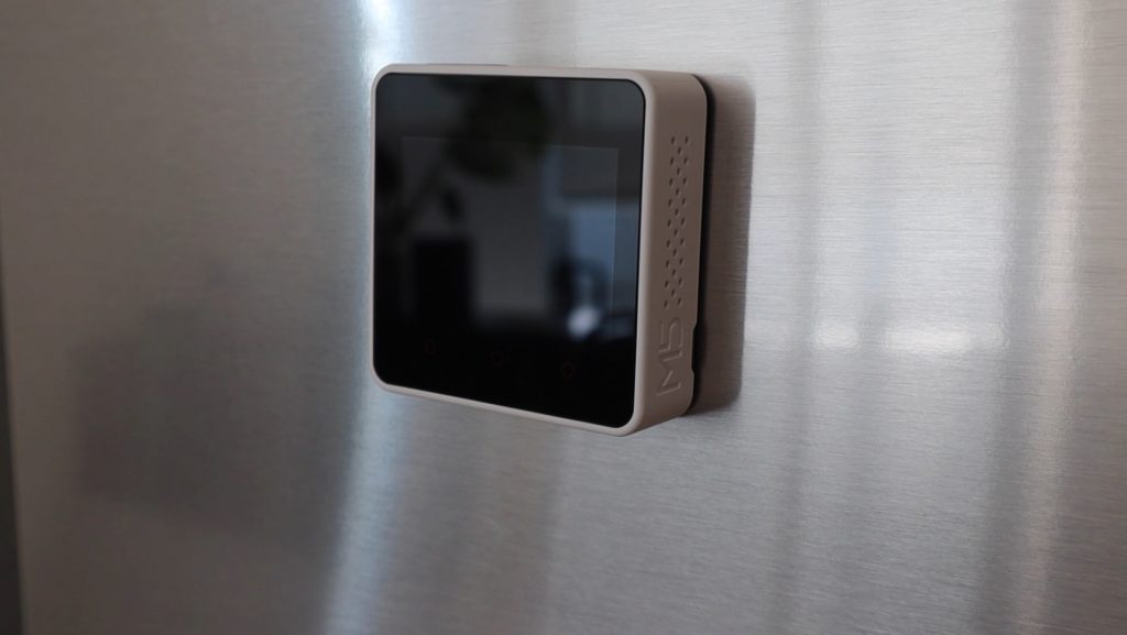
The M5Stack Core 2 has got magnetic feet, so you can easily stick it to a white-board or your fridge as a control pane or dashboard.
Specifications:
| ESP32-D0WD-V3 | 240MHz dual-core, 600 DMIPS, 520KB SRAM, Wi-Fi, dual-mode Bluetooth |
| Flash | 16MB |
| PSRAM | 8MB |
| Input Voltage | 5V @ 500mA |
| Interface | USB Type C x 1, GROVE(I2C+I/0+UART) x 1 |
| IPS LCD Screen | 2.0″@320*240 ILI9342C |
| Touch Screen | FT6336U |
| Speaker | 1W-0928 |
| LED | Green Power Indicator Light |
| Button | Power Button, RST Button, Virtual Screen Buttons * 3 |
| Vibration | Internal Vibration Motor |
| MIC | SPM1423 |
| I2S Power Amplifier | NS4168 |
| 6-axis IMU | MPU6886 |
| RTC | BM8563 |
| PMU | AXP192 |
| USB Chip | CP2104 |
| DC-DC Boost | SY7088 |
| TF card slot | 16G Max. |
| Lithium Battery | 390mAh @ 3.7V |
| Antenna | 2.4G 3D Antenna |
| Operating Temperature | 32°F to 104°F ( 0°C to 40°C ) |
| Net Weight | 52g |
| Gross Weight | 70g |
| Product Size | 54 x 54 x 16mm |
| Package Size | 75 x 60 x 20mm |
| Case Material | Plastic ( PC ) |
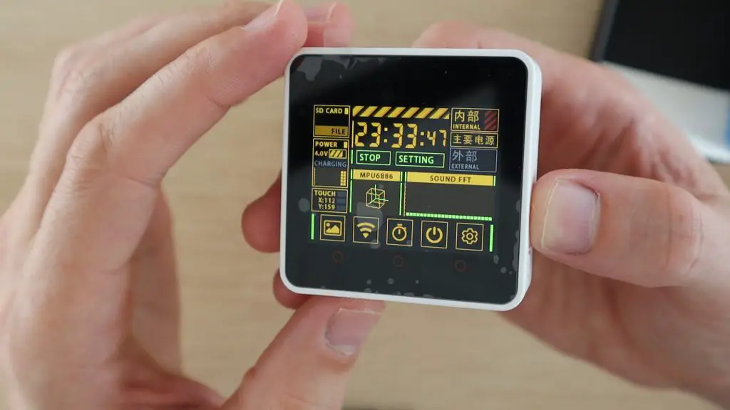
Preloaded Demo Program
The Core 2 also comes with a basic pre-loaded program that allows you to explore some of the features and sensors on the device, there is a clip of this program included in the video at the beginning of this post.
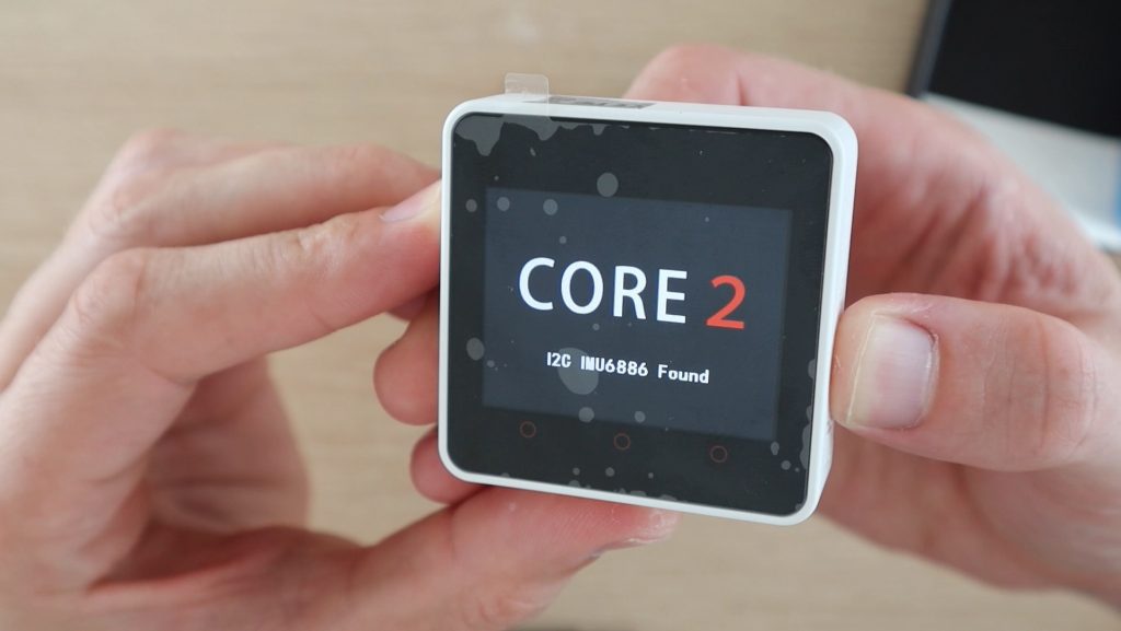
The program allows you to explore the IMU, touchscreen, microphone, SD card access, timer, clock and WiFi.
Getting Started With Ui Flow on the M5 Range
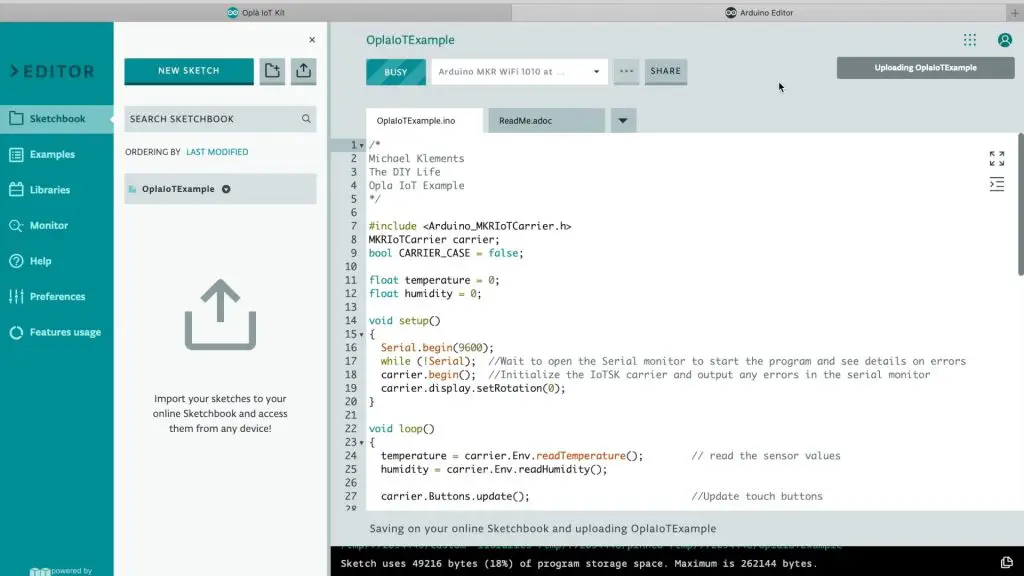
Next, let’s have a look at how to program these development boards. The boards are compatible with the Arduino IDE, and there is quite a lot of information on installing the boards into the IDE’s boards manager as well as programming them, but they are a bit easier to work with using micro-python.
The developer’s preferred method is to use a web-based IDE called Ui Flow.
To make use of this application, we need to download and install a driver on a computer and then flash the Ui Flow firmware to the device using M5Burner to enable it to communicate with the web application. You can also burn a couple of other pre-made programs to each device directly from the M5Burner tool.
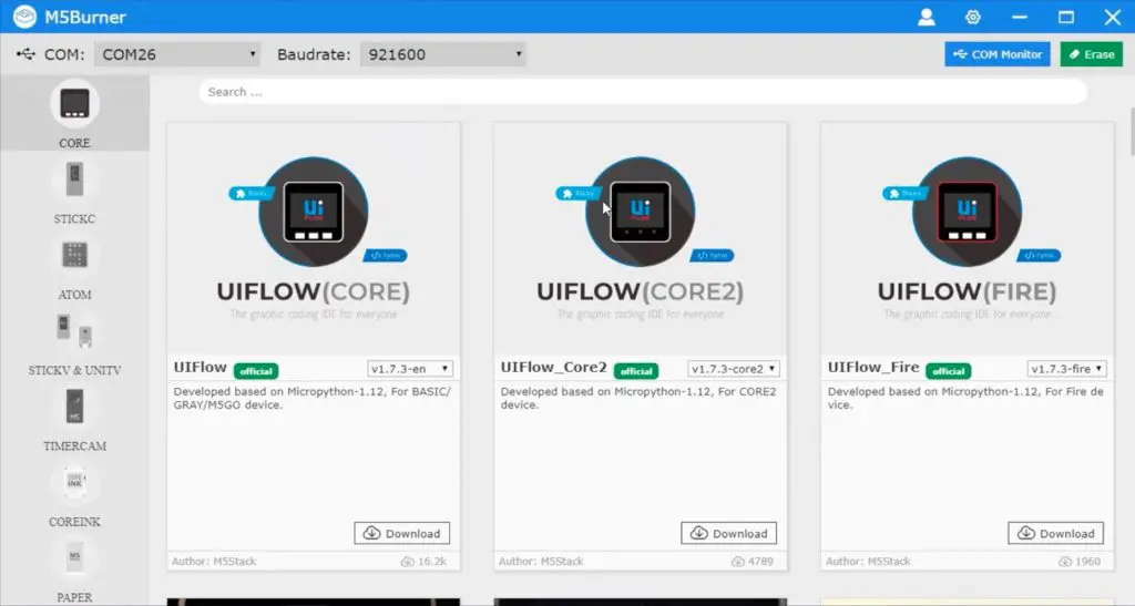
M5Burner is pretty intuitive, especially if you’ve worked with the Arduino IDE before, you simply select your board, the COM port, baudrate, and then choose the software that you’d like to install on the device.
We’re going to burn the latest version of Ui Flow to both the Core and Stick devices.
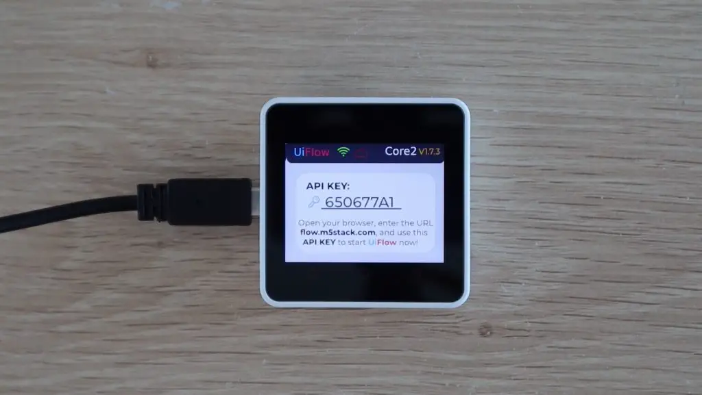
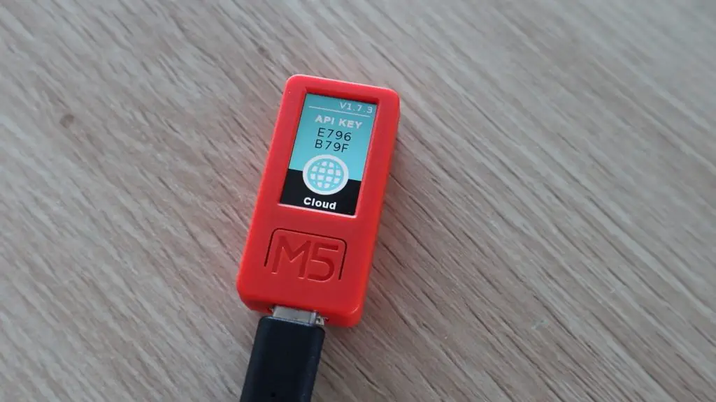
One of the best features of Ui Flow is that it is able to be used wirelessly. The device connects to your WiFi network and generates an API key, and you can then program the device from your browser without any cables, even from a remote location.
This sounded to me like it had the potential to be buggy and slow, but I’ve been really impressed with how well this works. I’ve used it to load a number of programs and revisions and I’ve never had any communication problems with it. It also uploaded the code to the device in just a couple of seconds, usually well under 5 seconds.
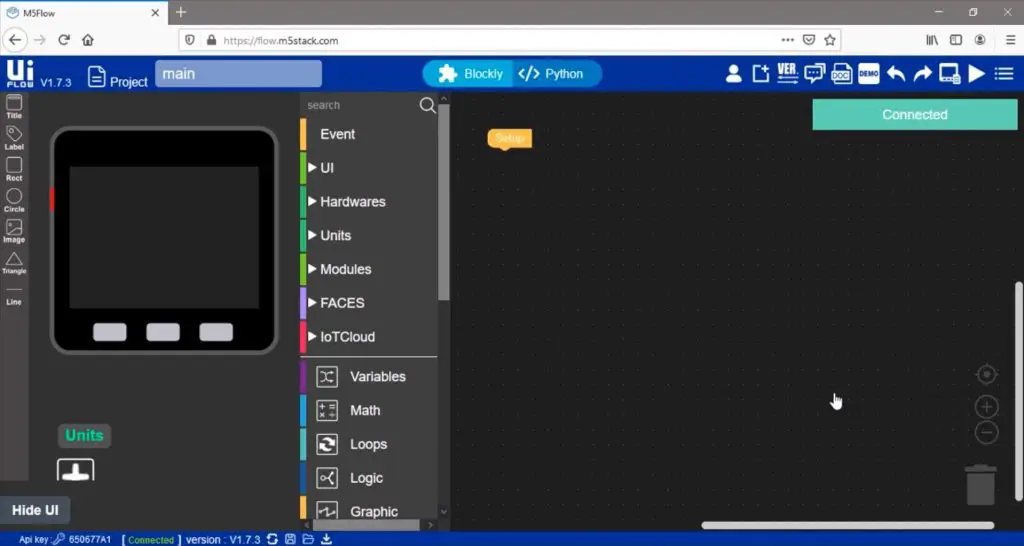
Ui Flow is an intuitive drag and drop, block coding IDE, which makes it really easy to get basic programs up and running. You can also switch between block and python modes to add functionality or edit the actual code being generated.
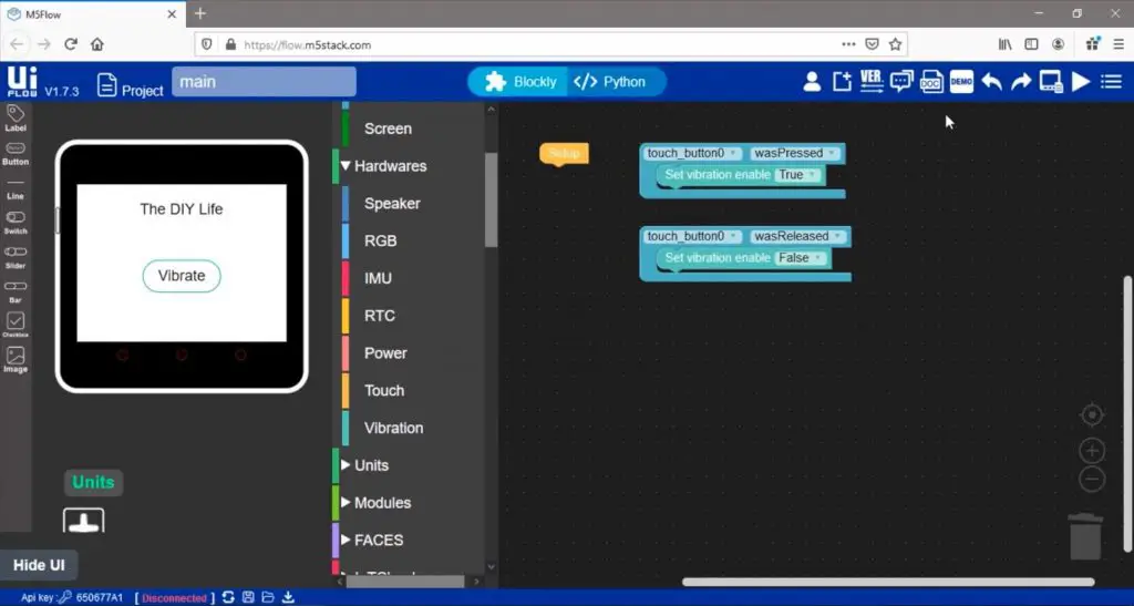
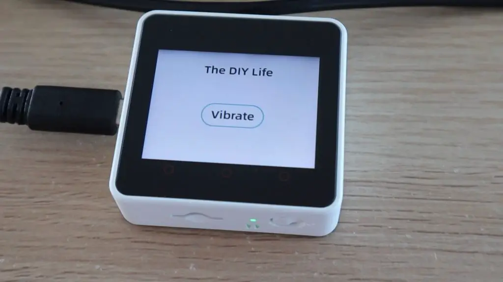
We can literally make a program and have it running on the device in a couple of minutes. Here I just made a button to drive the internal vibration motor when it’s pushed.
When you click on upload or run, the device receives the code from the IDE and then starts running it.
Making A Basic Home Automation Control Panel On The M5Stack Core 2
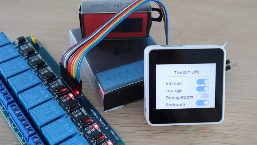
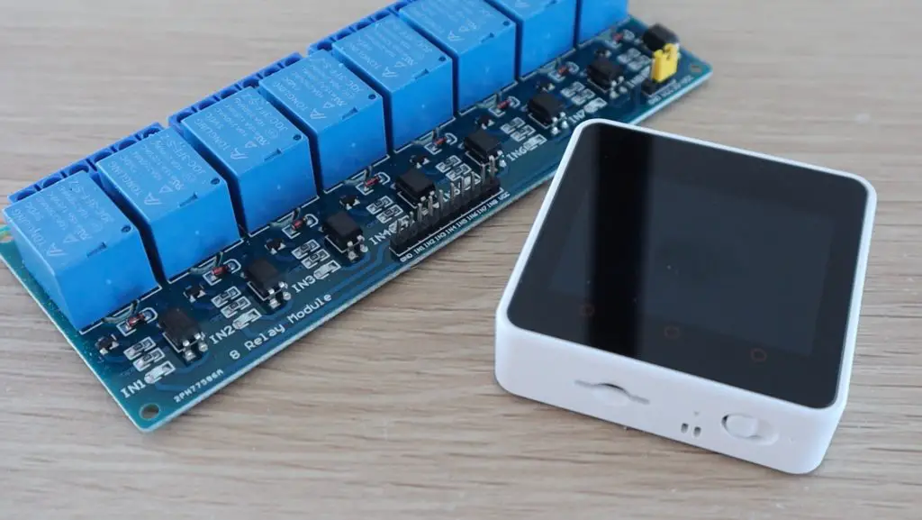
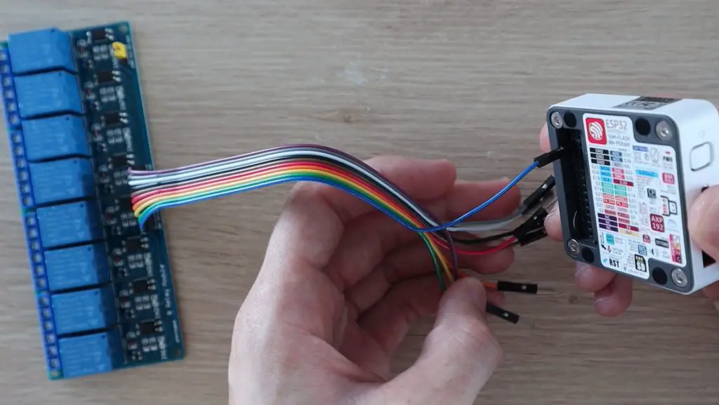
Next, I wanted to try making a program that used some of the IO pins, so I decided to try and make a basic home automation control panel using a relay board which I had lying around.
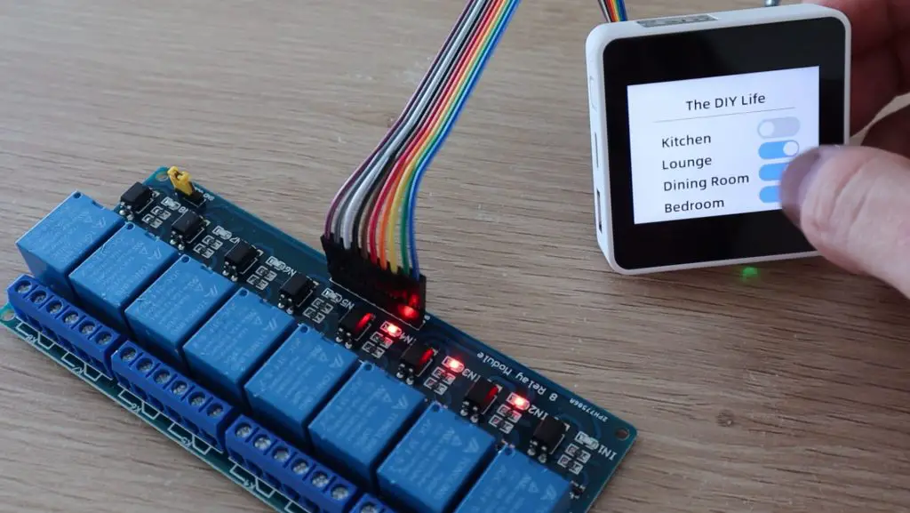
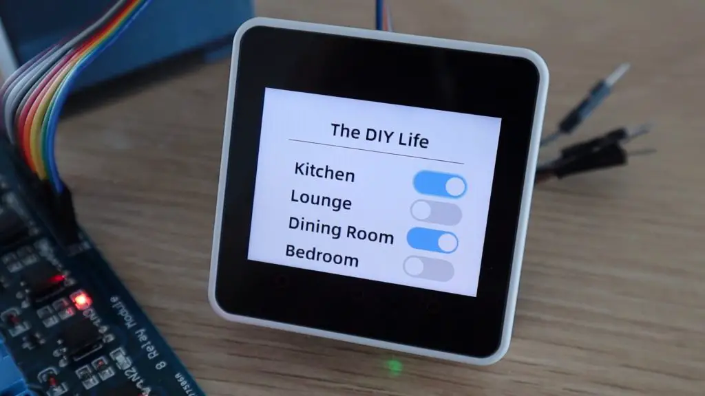
I dropped in four slider switches to drive a relay for each room and then added some digital IO blocks to set each pin high or low depending on the state of the button.
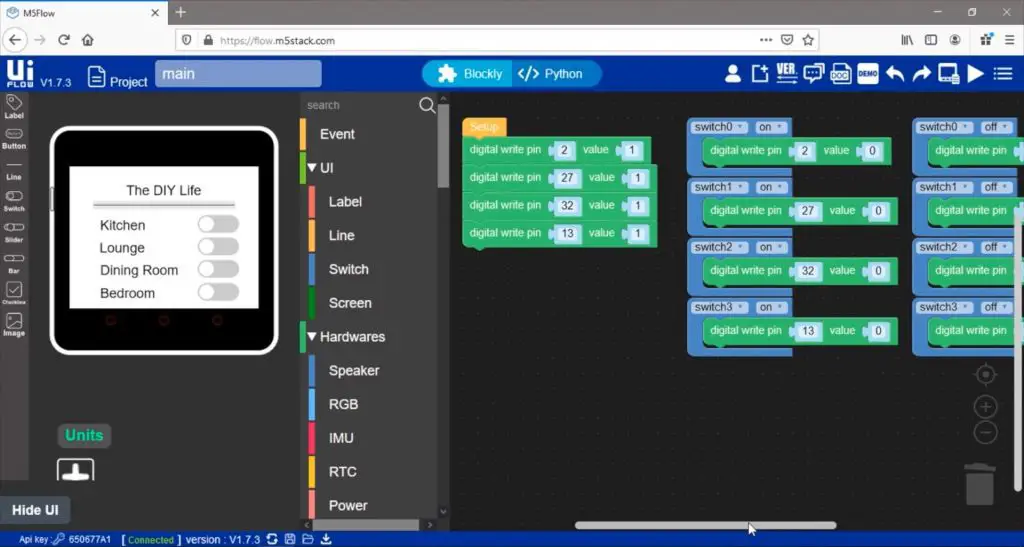
Never having used Ui Flow before, I did have to do some searching through the menus/options for certain blocks, but this whole program took around 5 minutes to make and get ready to upload to the device. It really is easy to use, even for a beginner.
I then plugged the relay module into the IO pins (pins 2, 27, 32 and 13) and uploaded the code to the Core 2.
It looks like it’s all working the way it should. You can turn multiple rooms on at once and the sliders indicate the status of each switch or relay.
I didn’t want to plug all 8 relays in at once as I’m not yet sure what the Core 2’s power supply capacity is and this was being driven straight from the Core 2’s 5V supply, not an external supply. If you’re using a large relay module like this then it’s a better idea to supply the relays using an external 5V supply.
Connecting Sensors To The M5StickC Plus
Next, let’s look at running a program on the M5StickC Plus which uses the analogue inputs. The whole process is pretty similar, it’s just a matter of selecting a different device in M5Burner and then in Ui Flow.
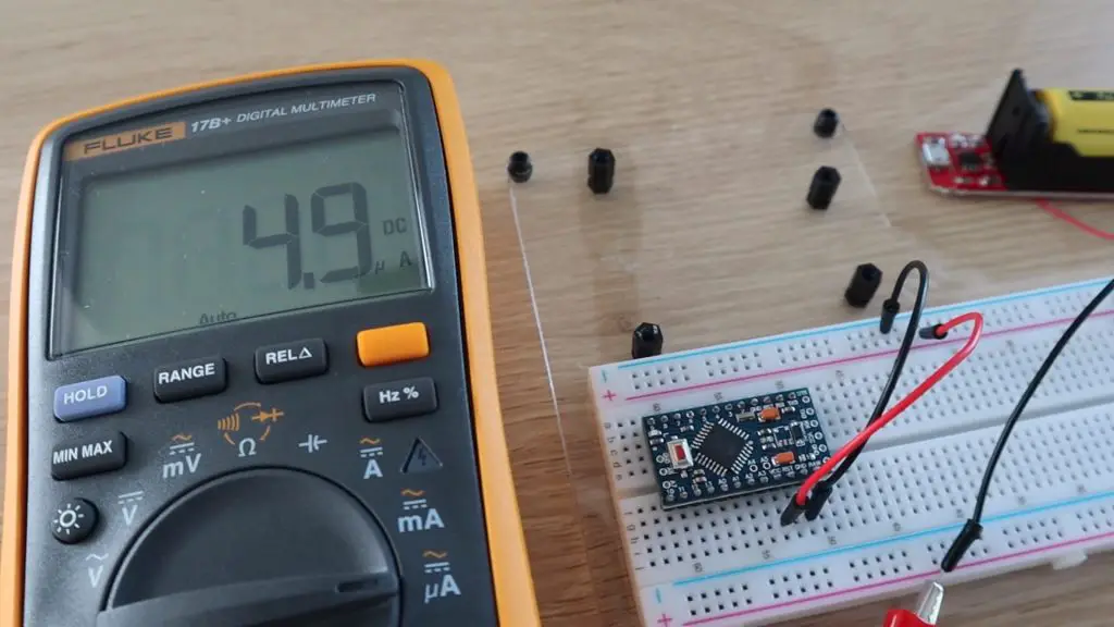
We’ll start by creating a program to display the X and Y co-ordinates from an external joystick. I’ve connected a basic two axis joystick to the grove port on the bottom of the M5Stick.
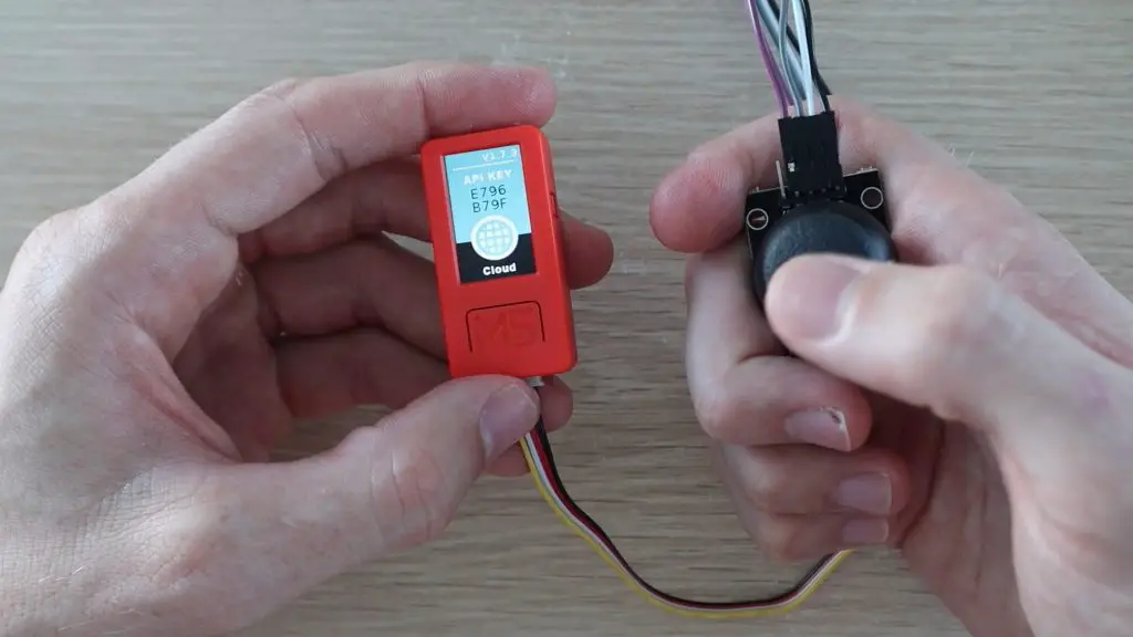
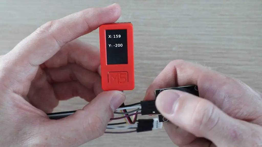
Our block code just takes a reading from each of the analogue inputs, maps these to a range between -200 and 200 and then displays this on the M5Stick’s display.
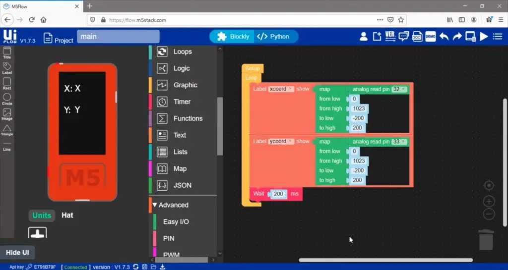
It’s obviously not scaled properly, but it works pretty well for a first pass.
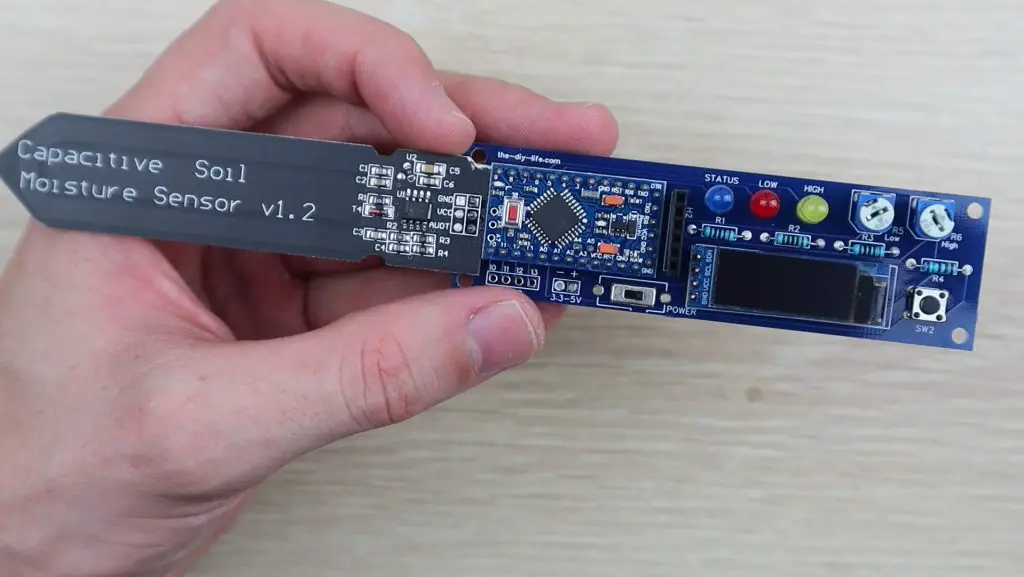
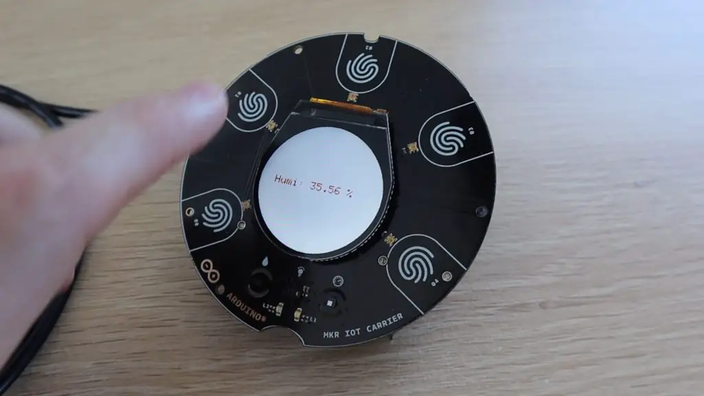
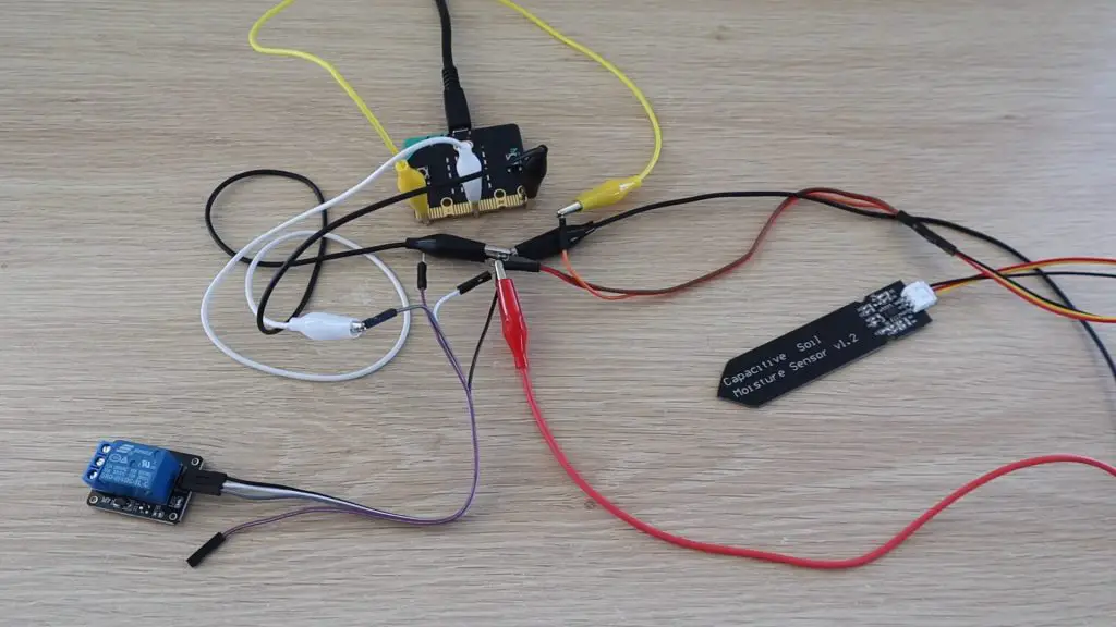
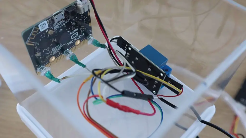
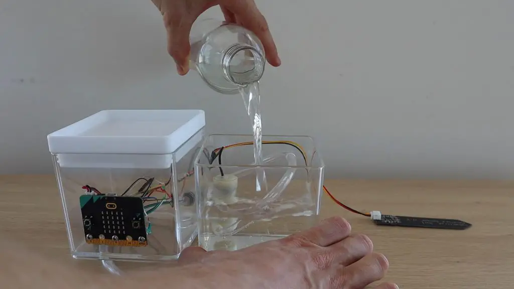
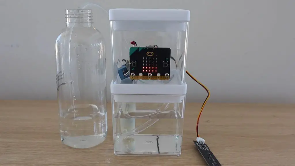
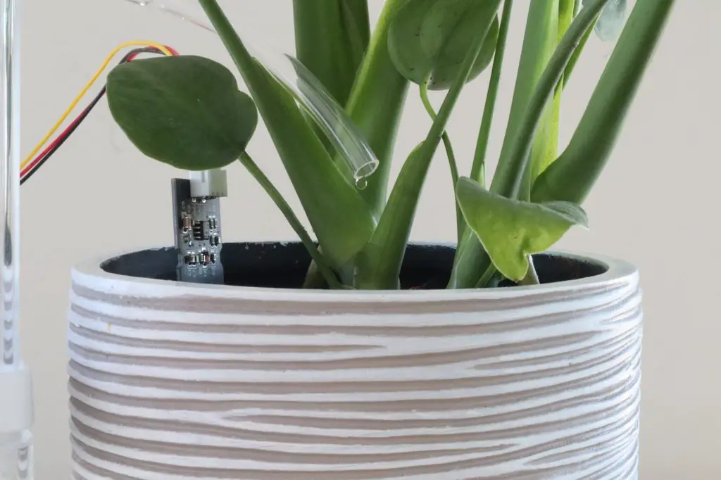
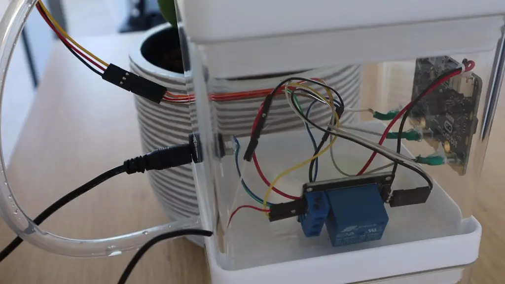
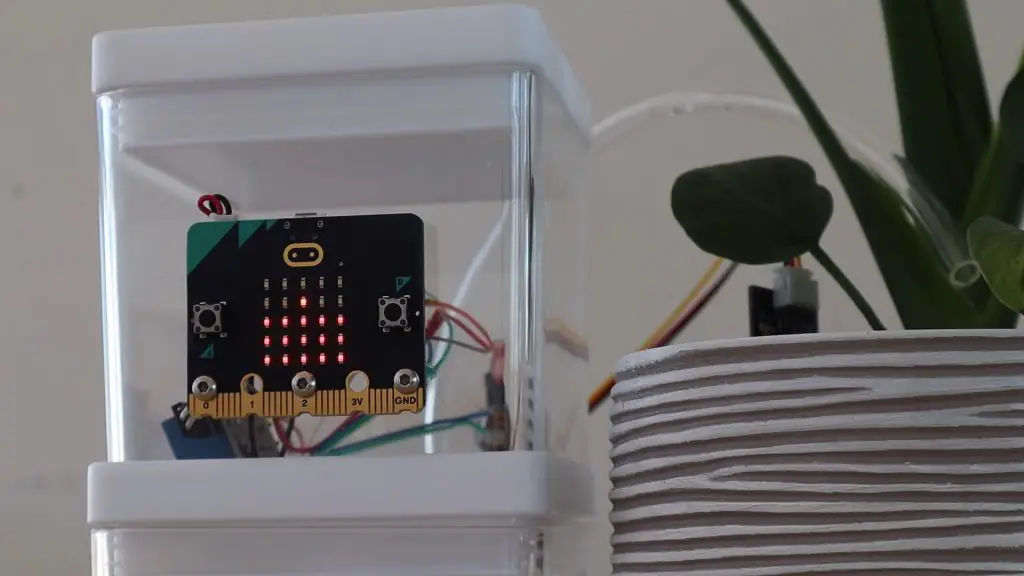
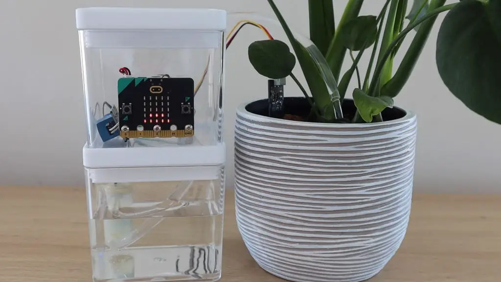
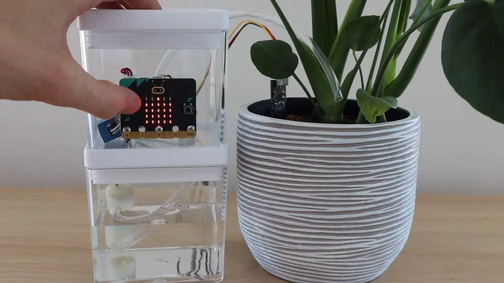
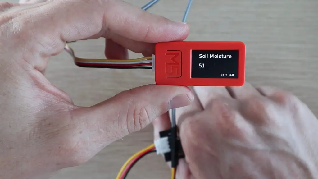
We can also replace the joystick with a sensor, like this soil moisture sensor and modify the program to display the soil moisture level.
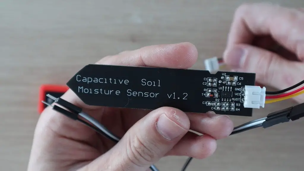
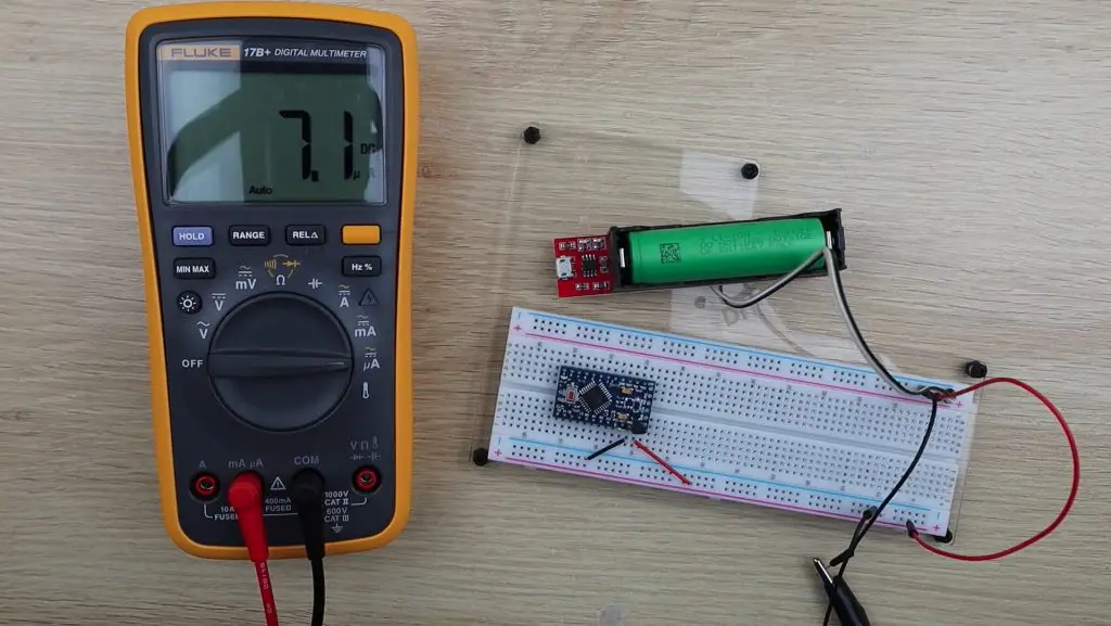
We’re now just going to be using a single analogue input and we’ll also add a battery voltage indicator on the display.
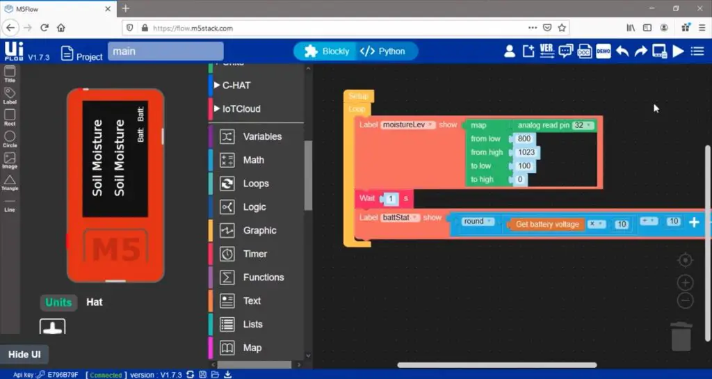
So we’ve now got a basic soil moisture level and our battery voltage being displayed on our M5Stick.
Final Thoughts
I think these are great all-in-one devices to get started with electronics and rapid-prototyping. I like that they’ve included a couple of built-in sensors and IO options. These, along with the physical buttons and colour display mean that you can already start building some basic programs right out of the box. I also like that you’re able to use the Arduino IDE if you’re already comfortable with it, but there are also easier options available, like Ui Flow.
If you’d like to build more complex projects, then you have the option of using plug-and-play grove sensors, or take it a step further and use the built-in header pins.
Ui Flow’s block coding makes programming the M5 devices really easy, but you’re still able to access some more powerful options through the micro-python editor as well. You also really need to try the remote programming over WiFi feature as well, it’s fast and convenient.
If you’re looking for a basic device for tinkering then the M5StickC Plus will do just fine. If you’d like to get a bit more functionality and be able to add a wide range of sensors and devices later, then have a look at the M5Stack Core 2.
Let me know what you think of these two devices and Ui Flow in the comments section below.