Today we’re going to be answering a question that has come up quite a lot in videos where I’ve used a small purpose-built UPS to power a Raspberry Pi – that is whether you could just use a power bank instead.
Here’s my video answer to the question, read on for the write-up:
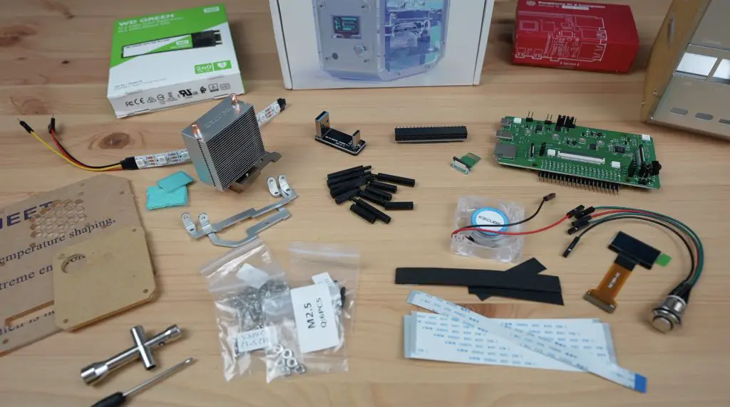
Components & Equipment Used For The Test
- Shargeek Storm 2 (Web Store) – Buy Here
- Shargeek Storm 2 (Amazon) – Buy Here
- Alternate Power Banks – Buy Here
- Pi Sugar 3 Plus UPS – Buy Here
- Pi UPS – Buy Here
- Portable Monitor – Buy Here
Tool & Equipment Used:
Some of the above parts are affiliate links. By purchasing products through the above links, you’ll be supporting this channel, at no additional cost to you.
UPS’ Used In Previous Projects
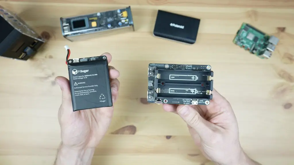
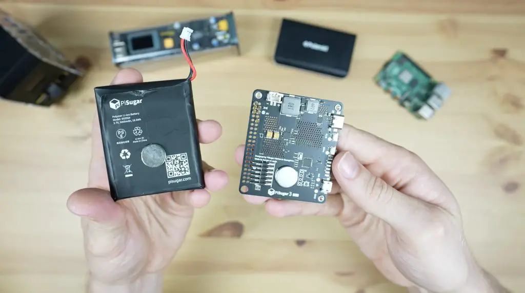
The UPS hats or shields that I’ve used in previous videos are these two, the Pi Sugar 3 Plus and the Geekworm UPS V5:
I used the Geekworm UPS V5 in my mini desktop case build. This UPS costs around $35 to $40 without batteries. It takes two 18650 lithium-ion cells and uses these to provide power through three USB ports on the front of the hat and to inject power to the Pi through the GPIO pins. It’s also got an I2C bus which transmits a range of data to the Pi like whether it is plugged in and what the battery capacity is, and you can also get your Pi to safely shut down when the battery voltage drops below a certain limit.
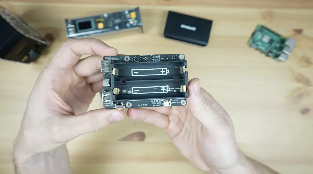

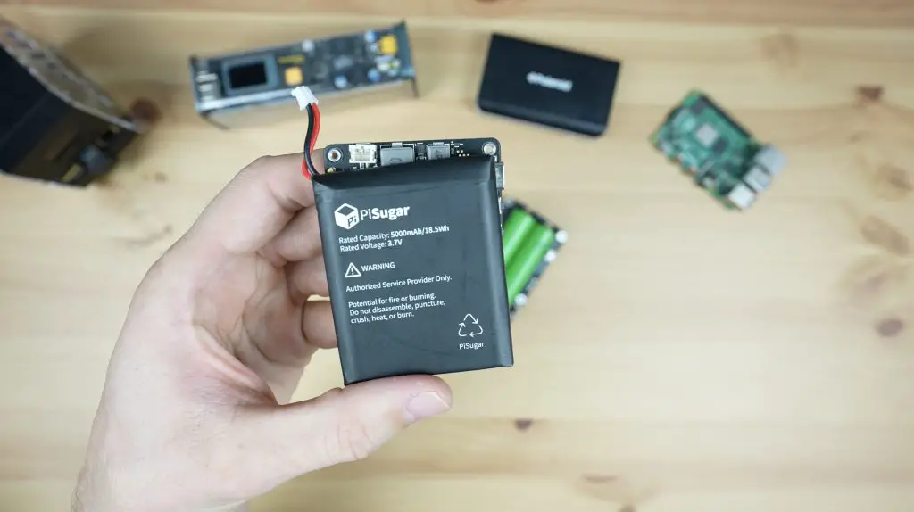
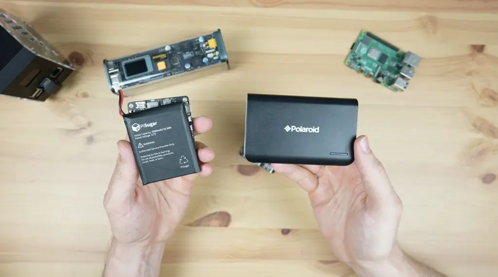
I used the Pi Sugar 3 Plus in my mini server rack build. This one costs around $50 and comes with an included 5000mAh battery pack. This has largely the same features as the Geekworm UPS but it doesn’t have the USB ports on the front. It does however have a better interface, the settings can all be adjusted and managed through a web dashboard rather than through Python scripts, and I found it to be a lot more stable and reliable.
So the main question is, could you use a power bank to power a Raspberry Pi? Then there is the follow-up question, if you can then why would you use one of these UPS shields instead? Power banks are often a lot cheaper or have significantly higher battery capacity.
Which Power Banks Are We Going To Test?
To find out if we can use a power bank, I’ve got two to test. These represent the two extremes of what is available in the power bank market.

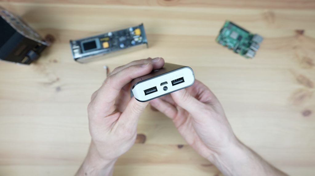
The first is a cheap $15 power bank that has a 6000mAh battery. It can output up to 2.1A through two USB type A ports. It is charged at a maximum of 1A through a microUSB port between them.

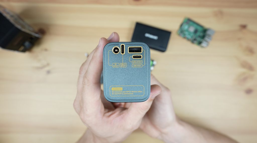
The second is the Shargeek Storm 2. This is a $220 power bank that has a 25,600mAh battery. It also has a range of USB ports including one USB type A port and two USB type C ports that support power delivery. In addition to these, there is also a DC barrel jack that supports DC input and output within an adjustable range.

Shargeek sent me the Storm 2 to try out and share with you, so I thought it would be a good device for this comparison. You may have already seen one of their eye-catching power banks online with a cyberpunk-style transparent case, leaving the batteries and PCB visible. But apart from the stylish design, they also offer great performance and a host of features which we’ll take a look at during this comparison.


Can We Power A Raspberry Pi With A Power Bank?
The main issue I see when people ask whether they can just use a power bank is that they’re generally asking because it’s an easy way to save money. A $20 power bank is obviously half the price of a $40 UPS and you can still use it to power and charge other devices.
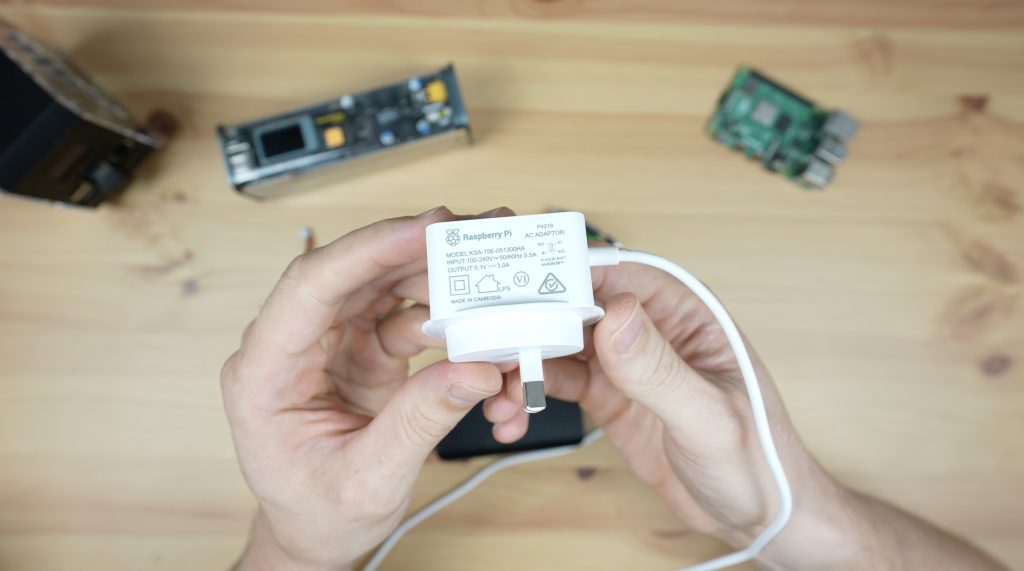
The issue is that these cheap power banks often only have USB A ports and usually only support a little over 2A, or about 10W. If you’re familiar with the Pi’s power supply, this is a 3A, or 15W USB C supply.
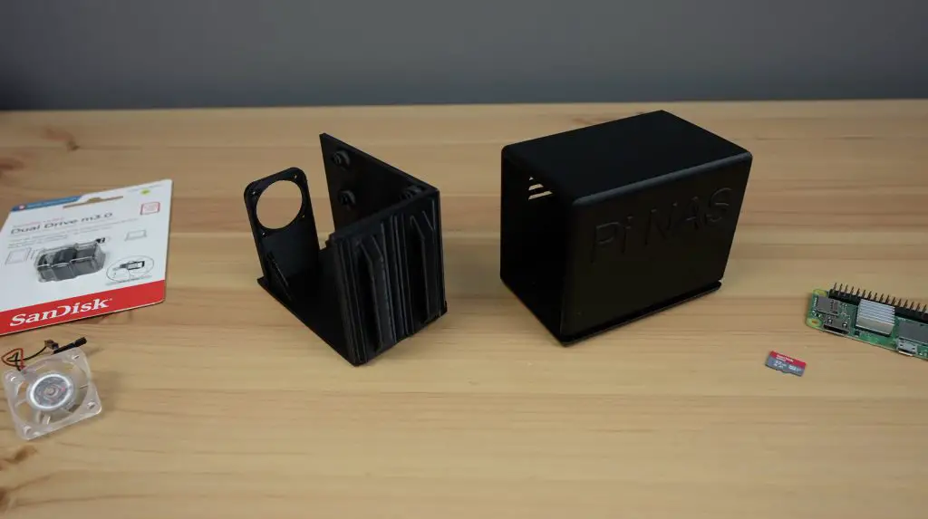
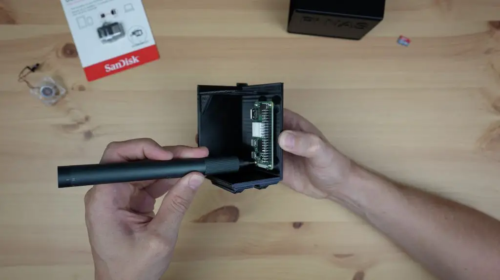
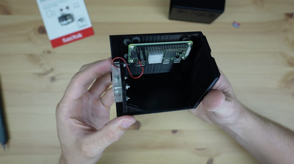
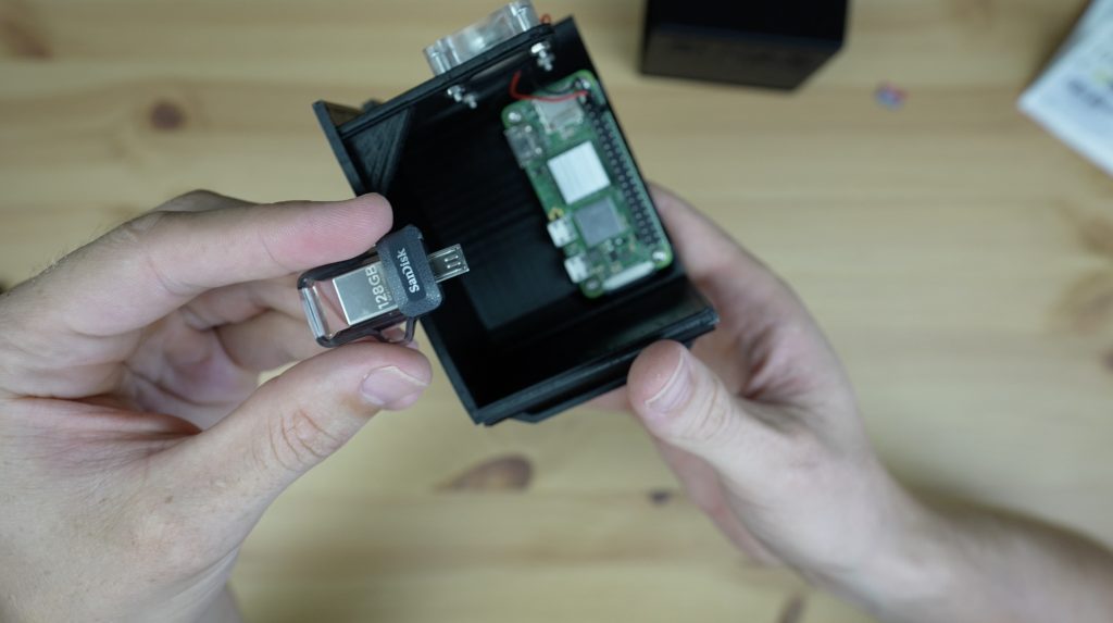
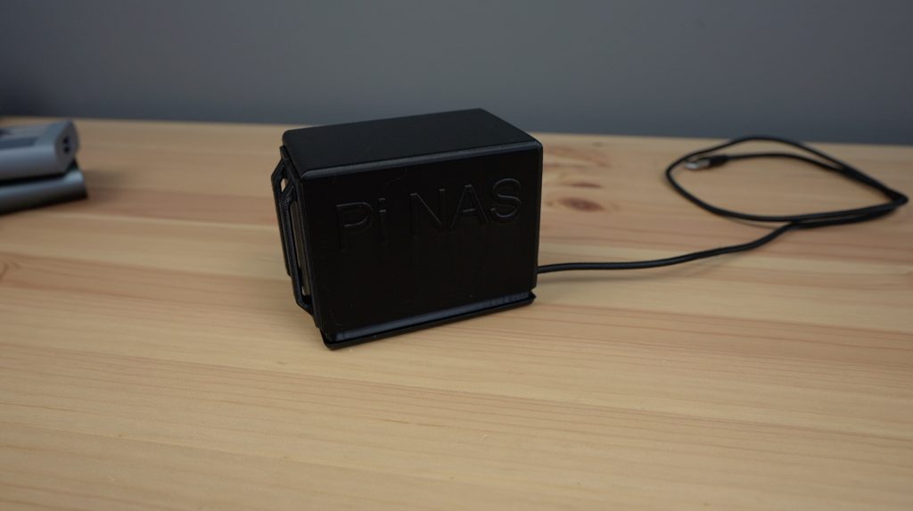
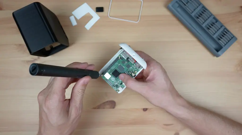
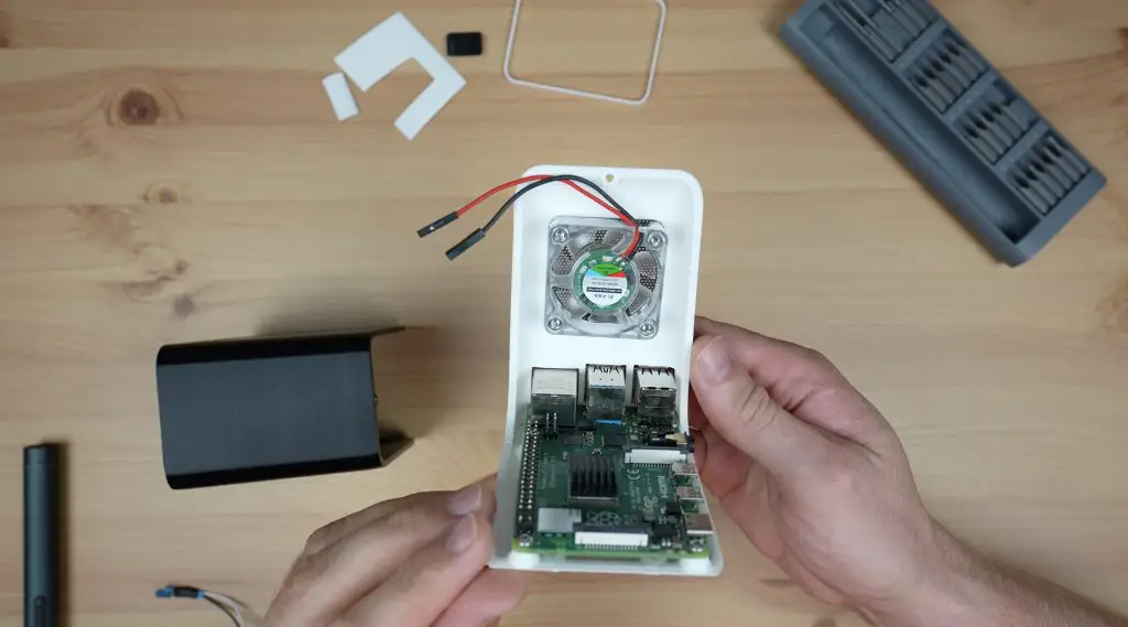
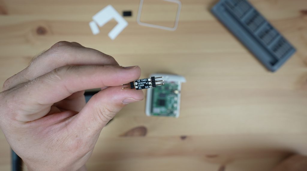
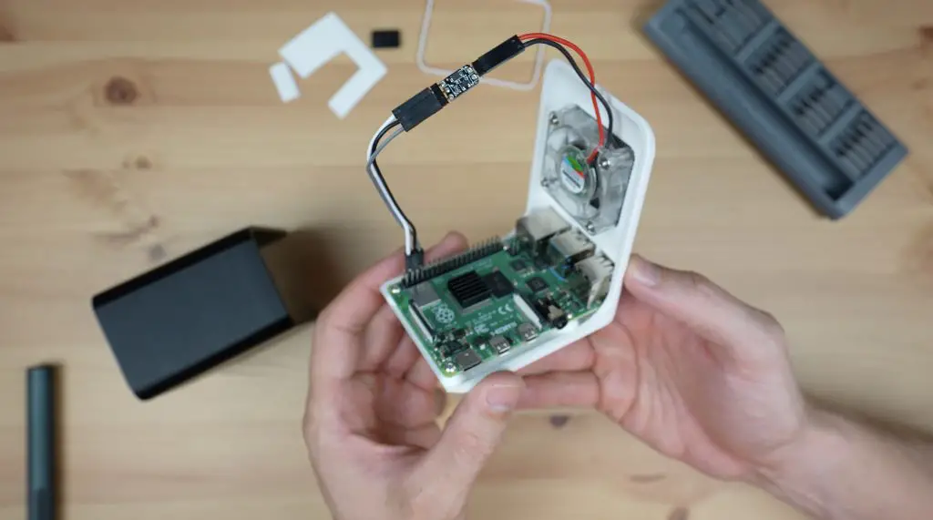
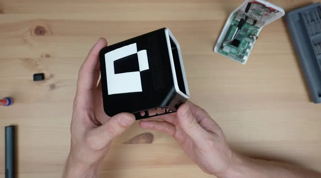
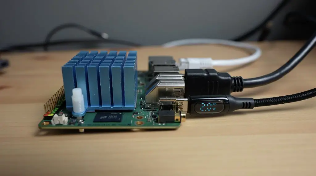
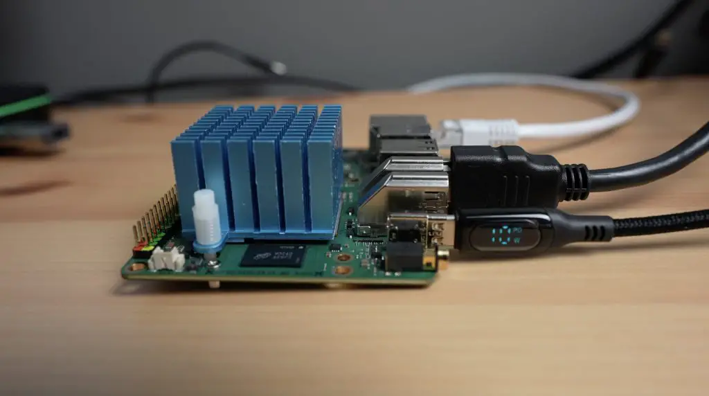
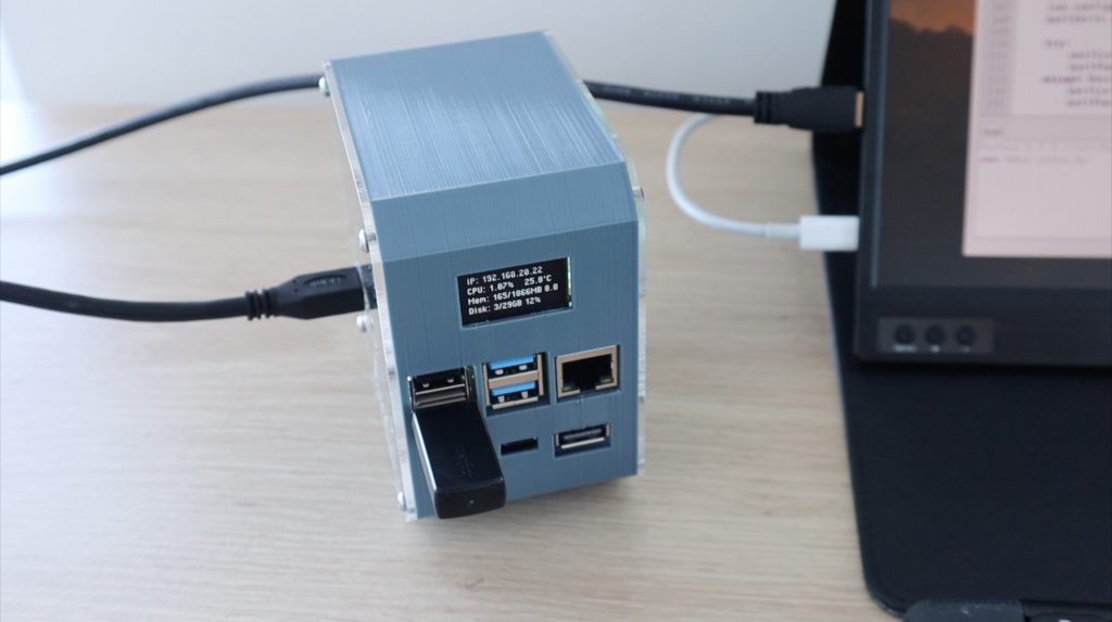
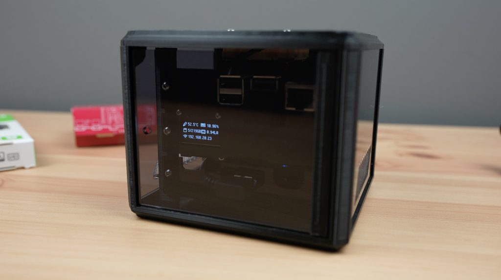
Now this is probably not an issue if you’re running a barebones Pi with no connected drives or peripherals, but it will likely be a problem if you try powering a full desktop setup like the one in my 3D-printed desktop case. This has an SSD, an OLED display, a PWM fan and its got a wireless mouse and keyboard receiver plugged into it.

So let’s start by trying to power a Pi by itself with our first power bank.

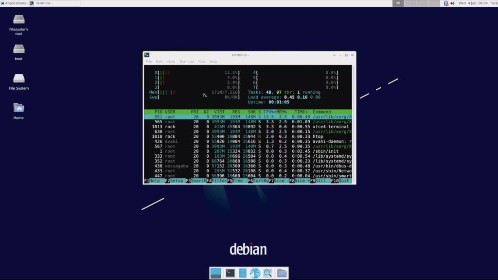
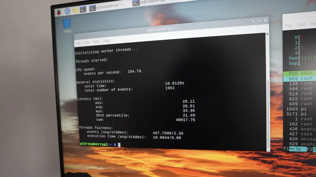
So that has booted up and doesn’t seem to have any issues. I can open up a Chromium tab or VLC media player (which puts a load onto the CPU) and we don’t get any under-voltage warnings coming from the Pi.
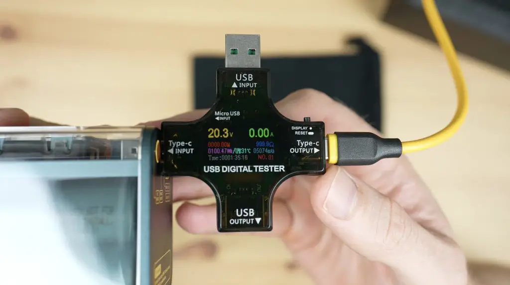
I put my USB power meter onto it and found that it was drawing a little under half an amp when idle on the desktop.

Next, let’s try powering the Pi in my desktop case setup.
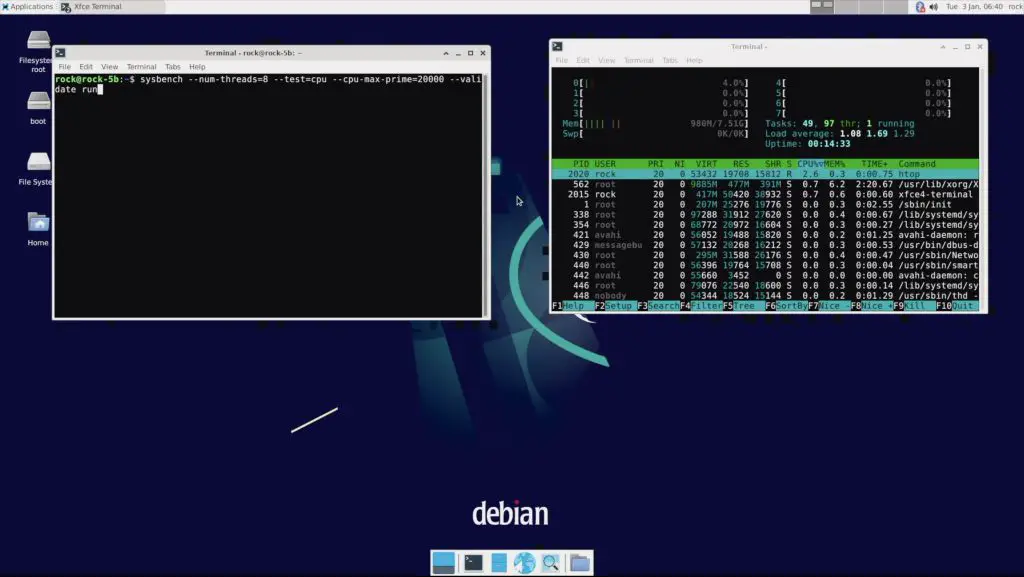
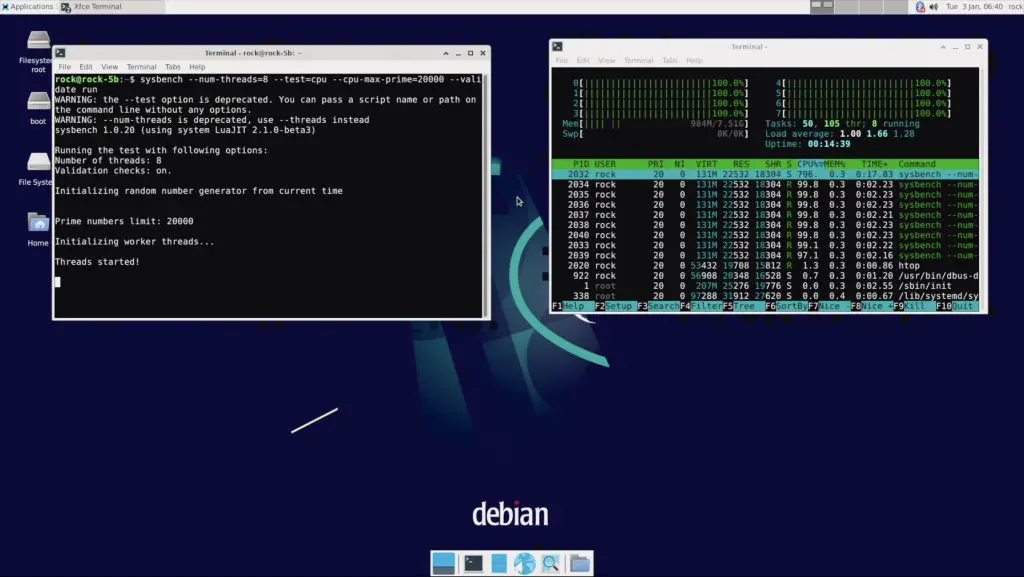
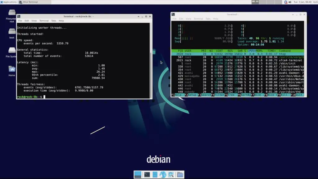
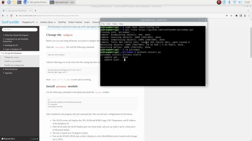
The first time I tried to boot it up, it looked like it was going to start up. It loaded the stats display script but then locked up.
I tried it again a few times and it did eventually boot up but instantly came up with a low-power warning. The little lighting bolt warning stays up almost continuously and the Pi is clearly running at reduced performance – it’s very lagging even just moving windows around.

With my power meter connected, it looks like the Pi uses a maximum of around 1.4A when booting up and then stabilises under 1A when on the desktop.
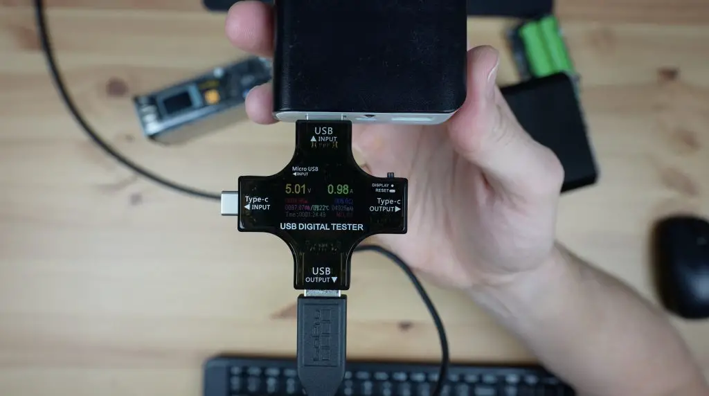
At 1A we’re still well below the 2A rating on the power bank so it should be able to keep the voltage over 5V but it doesn’t. So this cheaper power bank is not really suitable to run any more than a barebones Pi.
So now let’s try powering it with the Storm 2.
The Storm 2’s type A port can do 18W, so we should be able to power the Pi from that port without any issues but it also has two USB type C ports which both support power delivery. The one marked C1 can do up to 100W and the one marked C2 can do up to 30W. I’m going to use the Storm 2’s included USB C cable to power the Pi using the lower-powered USB C port.
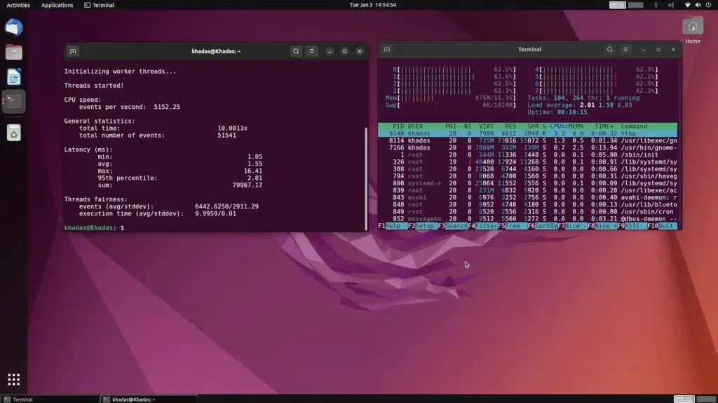
This time the Pi has booted up and is running without any low-voltage warnings. It’s also a lot more responsive when opening up applications so it doesn’t seem to be performance limited.
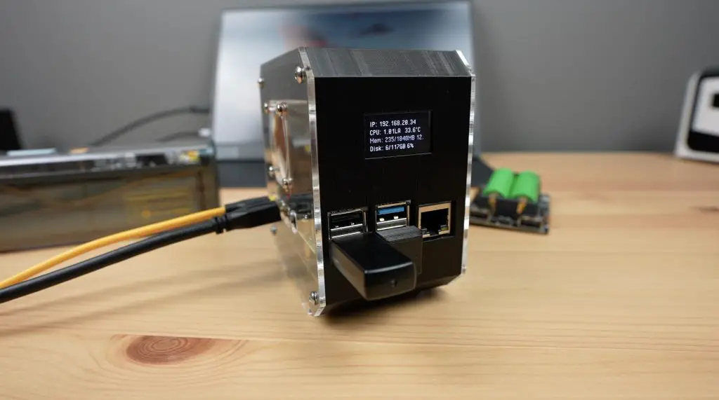

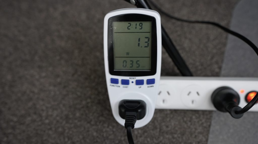
On the Storm’s display, we can see that it is drawing a little over 4W.

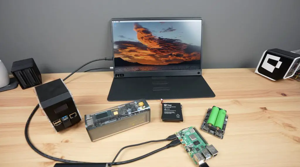
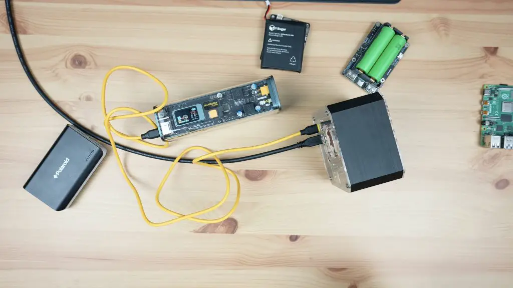
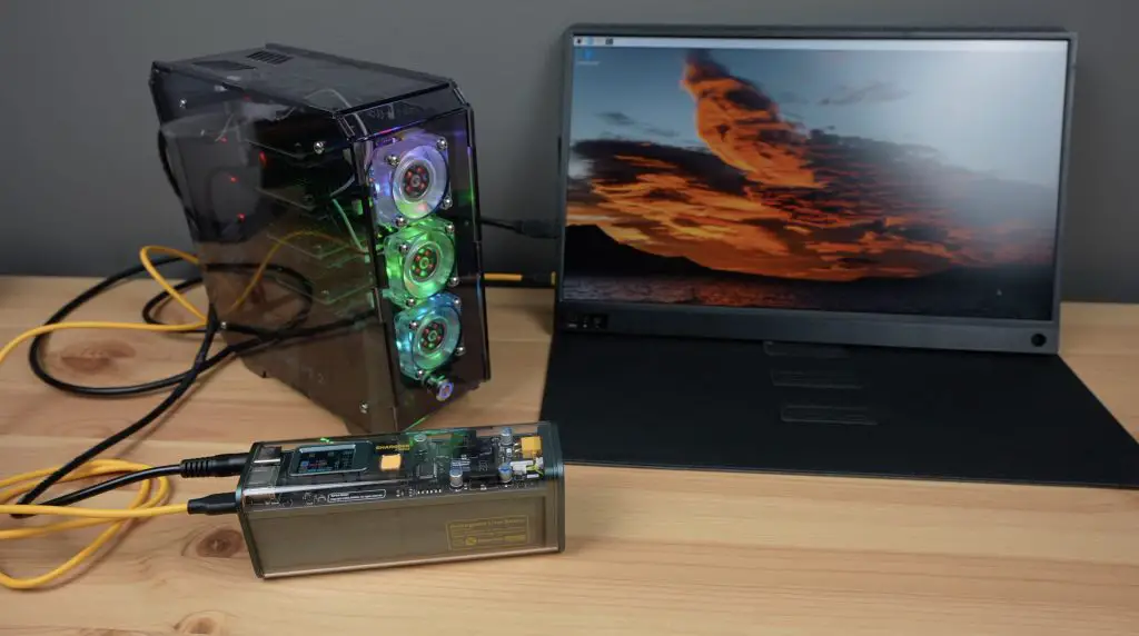
We’ve got a lot of capacity available, so let’s try to hook up the portable monitor to the Storm 2 as well so that our whole setup is running from the power bank.
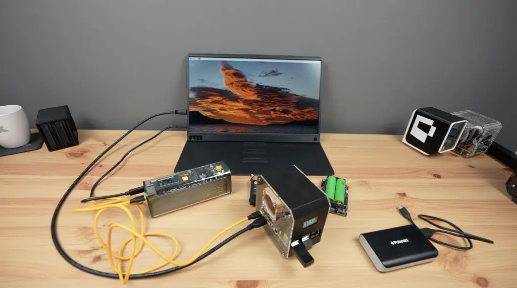
With the monitor added, we’re now drawing a little over 5W on the display’s port and under 5W on the Pi’s port, with a combination of just over 10W.
The Storm 2 has a 25,600mAh battery or more appropriately 93.5Wh, made up of 8 lithium-ion cells. So we could power this portable setup including the monitor for around 9 hours. Shargeek chose 93.5Wh as most airlines have a limit of 100Wh for power banks or portable batteries, so it is a high-capacity power bank but you can still travel with it.

The onboard controller has a built-in battery protection system which includes over-voltage protection, short circuit protection and extreme temperature protection. The lithium-ion cells are manufactured by Samsung, so are good quality, and the housing is V0 fireproof so they have taken safety seriously when designing it.
Can We Power Additional Pi’s With The Storm 2?
Another interesting feature of the Storm 2 is the DC barrel jack next to the USB ports. This can be used as either an input or an output and its voltage is adjustable through the display.

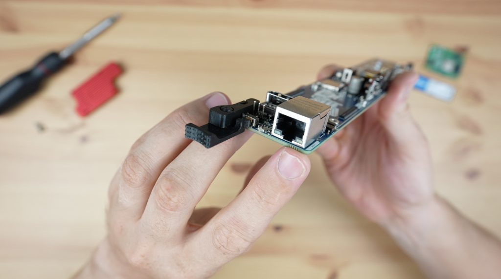
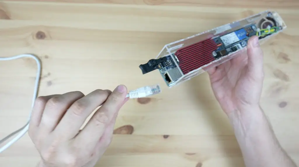
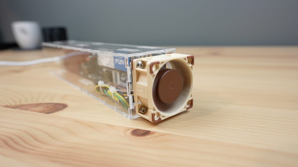
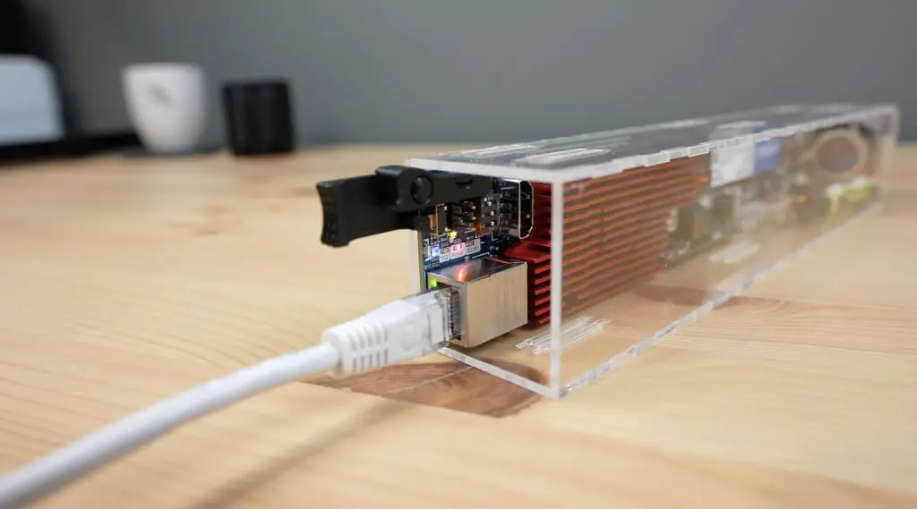
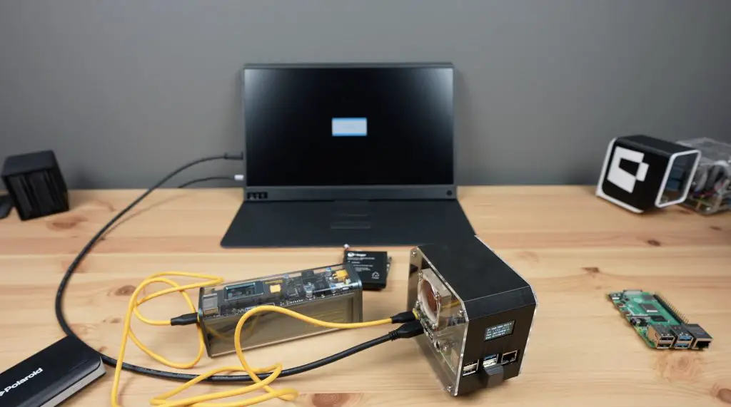
If we set it to 12V, we can even power my whole Turing Pi 2 build.
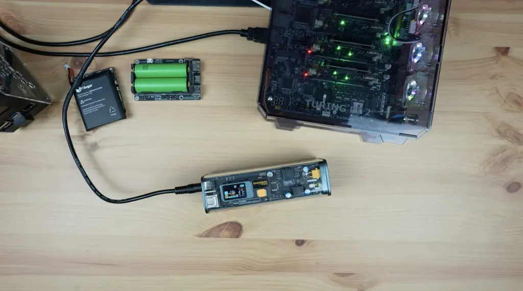
And even plug the monitor into it, drawing a total of 17W. So we could power this setup of 4 networked Pi’s in a fanned enclosure and with a portable monitor for over 5 hours.

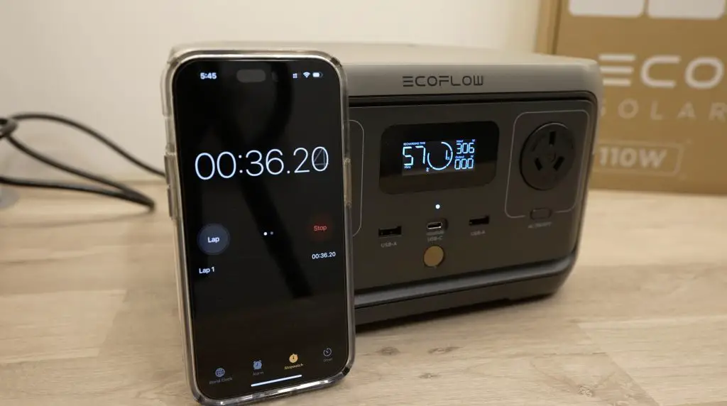
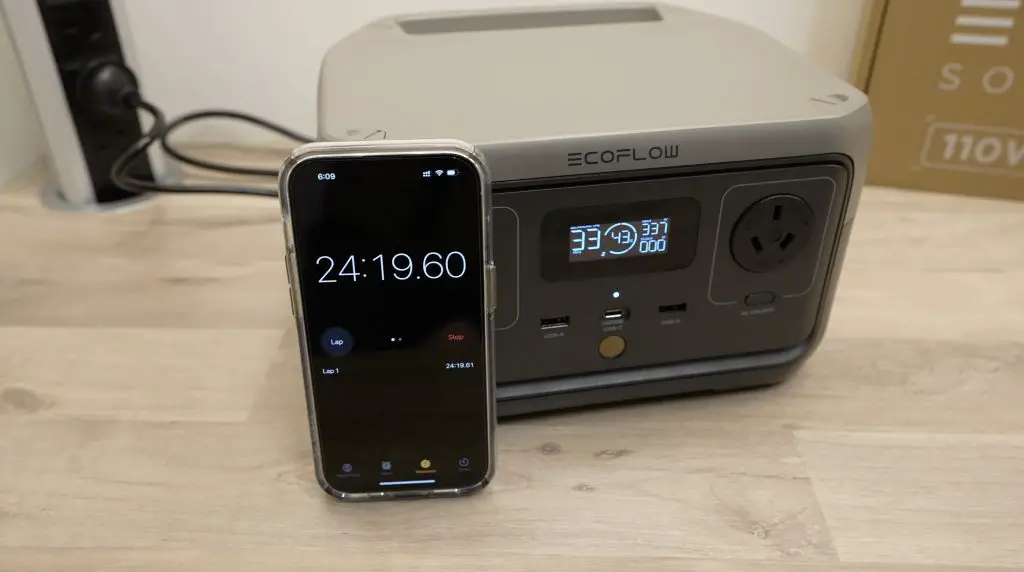
Once the battery is drained, Shargeek claim that you can fully recharge the Storm 2 in 1.5 hours. I tested this by fully draining it and then recharging it with my USB C adaptor from my MacBook which supports up to 140W. It charged up to 80% in an hour and reached 100% after 1 hour and 35 mins.
Why Use A UPS Instead Of A Power Bank?
So it clearly is possible to power a Raspberry Pi with the right power bank, and even additional peripherals like a portable display. So does this mean a power bank would be a better choice? Well, this is where it depends on what you want to do with it because a UPS and a Power Bank have similar features but are not really the same thing.

A power bank is great to make your Raspberry Pi setup portable for a period of time, but this is not why we use a UPS. A UPS is there to ensure that your Pi stays powered through minor power interruptions and in the event of an extended interruption, it gives the Pi an opportunity to safely shut down.
There are two important features that make a UPS different to a power bank.
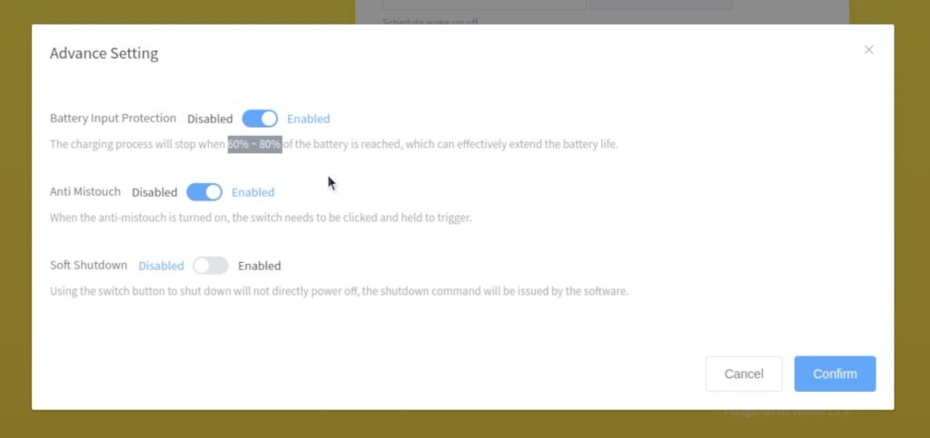
The first is that a UPS is designed to run for long periods of time with power on – and batteries don’t like being fully charged for long periods of time. So most good quality UPS’ will have a feature to limit the maximum charge and discharge level of the connected battery. They’ll then only charge or discharge the battery between these limits. This protects the battery and prolongs its life. They also usually direct power from the supply to the load once the battery is full so that you’re not constantly drawing power from the batteries – again prolonging their life.
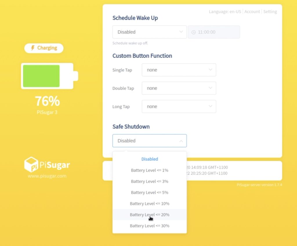
The second is something I’ve mentioned previously and that is that they are able to tell the Pi to safely shut down when the battery is running low. This protects your Pi and whatever you had running on it in the event of a longer power outage – something that a power bank won’t do either.
So it really depends on what you’re wanting to do with your Pi. If you are connecting batteries to it to keep it running through a power outage then a UPS is the correct choice. If you’re wanting to make your Pi setup portable then a good quality power bank is the correct choice, and you’ll be able to use it to power other things as well – just make sure that your power bank is able to meet the power requirements of the Pi. You’ll generally be ok with any power bank that can supply 3A through at least one of its ports, most likely a USB C port.
Final Thoughts On The Shargeek Storm 2
Shargeek have a range of good quality power banks and accessories available through their web store or on Amazon.


The Storm 2 sells for $229.00, which is obviously a lot of money for a power bank, but you’re getting a solid set of features and a quality product that’ll likely last for a number of years. Not many power banks even support power delivery, never mind doing it at up to 100W and the inclusion of the DC power output makes it quite versatile. You could probably power small laptops or mini computers directly from this port since they usually take an 18V input. Shargeek even offer a 30-day money-back guarantee if you’re not happy with your Storm 2.
So I hope this post has answered some of the questions that you might have had about powering your Pi with a power bank or a UPS. If you’ve got any other questions on either of these power supplies, leave a comment down below and I’ll try my best to answer it.